 Eric Hertz
The textual saga was described in the early logs of this project...
The basic jist is that I built an IBM PC/XT clone, based on stuff I had laying 'round the stockpiles... The Motherboard was in a box filled with scrapped PCBs, as was an ISA card, or two. Though some I was actually smart enough to store in a box specifically marked "ISA Cards", and some were even in anti-static bags. Most, on the other hand, were not.
Getting this system running was a bit**... it kept stringing me along with little minutes of utter surprise at the fact certain things worked-out, despite how they'd been abused over the years, or how unlikely they were, and then days on end of roadblocks with things that should've been easy, or with tools I'd been using in pretty-durn-functional states for quite some time.
The earlier logs describe it better... here's some photos.
-----------
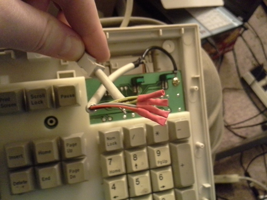
Dug through the ol' box of Keyboards, pretty certain I didn't have an XT keyboard (which is not at all compatible with AT/PS2)... and lucked-out with a nice surprise:

So, of course, this project was meant to be, right?
First things first, apparently somewhere down the road I thought it more likely I'd use the cables (I was kinda into MIDI, at the time... same connector) than that I'd use these old beat-up keyboards... so years ago I cut most of my grubby keyboards' cables and stored them separately... (and numerous times I'd thought to just dump that box of keyboards, glad I didn't). Dug through that box of cables and found exactly the right one... (!) Hadn't even been repurposed!
I can't recall what the result was, powering the system up that first time... was it a nasty long beep, or...?
Anyways, turns out the switch-settings on the motherboard were incorrectly set for an FPU. (Did I desocket the 8087 FPU long ago, explaining why I found one in my "unsorted chips" bin a few weeks earlier, or did the switches get bumped in all those years stored in a box with dozens of other scrap PCBs and no anti-static bags?)
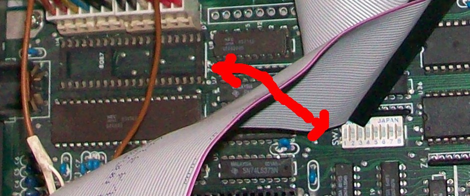
Changing the switch settings (nicely-documented on the web!) solved that problem!
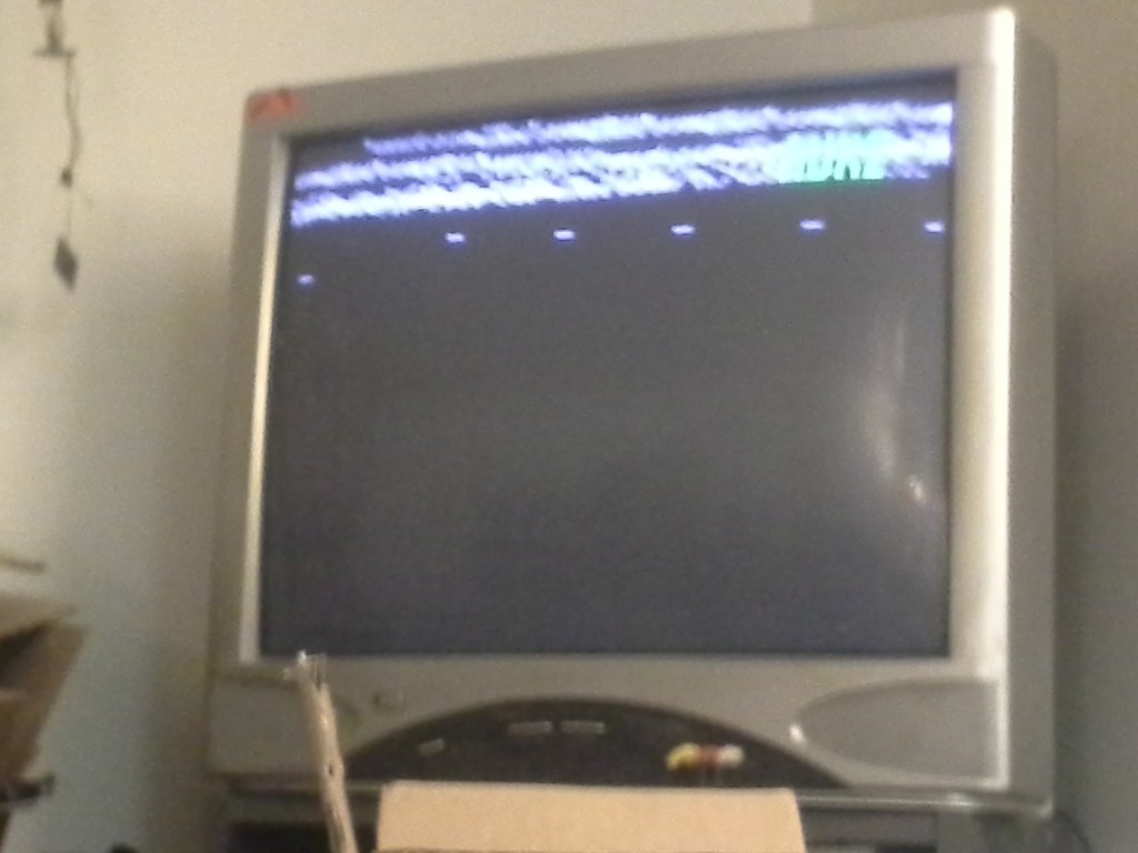
Next, the video card wasn't syncing up with the TV... In fact, for quite some time no video was showing up at all... until finally I connected it straight to my old CRT TV--rather'n an LCD, nor through a VCR--when I saw something, but not legible.
So I fought long-and-hard with the color-burst adjustment capacitor on the motherboard... It seemed to get better with adjustment but never quite legible, so I cut the trace between the capacitor and the crystal, and experimented with series caps. No go, there, so tried a parallel cap, still nogo... Finally replaced the crystal altogether... Still nogo.
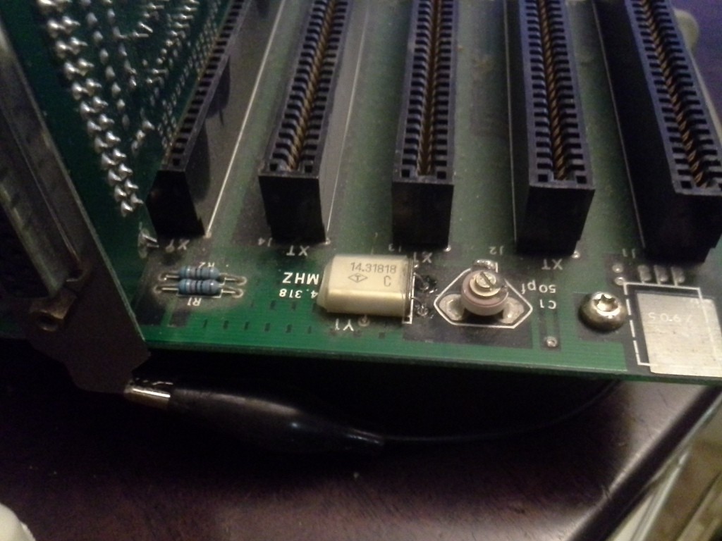
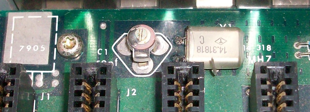
Note that the board is labelled 14.318MHz, as I recall its crystal also being labelled. I grabbed a 14.31818MHz crystal this time.
I 'scoped it out... and I can't explain this, but my 'scope showed 14.04MHz, even after these changes, and varying the capacitor had only a *tiny* change in frequency. 14.04MHz is *way* off, so I figured maybe the capacitor was old-and-crusty or something... maybe the loading of the driver circuit varied elsewhere... I dunno. Another thought, early on, was that the original crystal might've "cracked" in the decades of abuse, which would detune it, right?
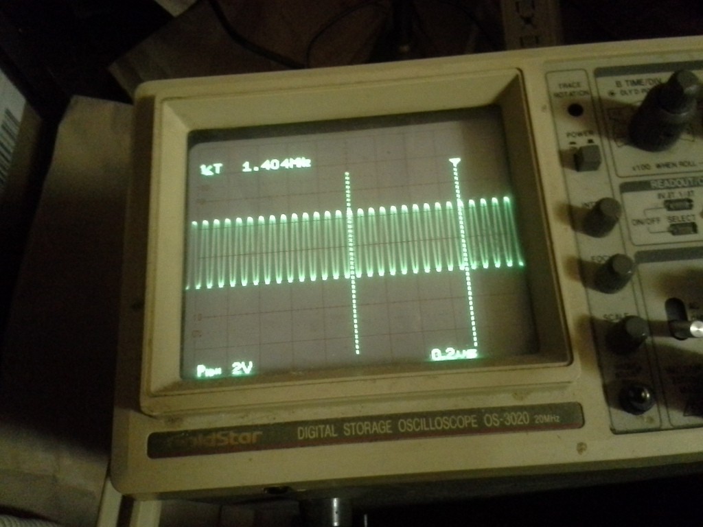
I'm sure I've checked this countless times... That's ten peaks, 14.04MHz. I don't get it, and you'll understand why, when we get through this ordeal...
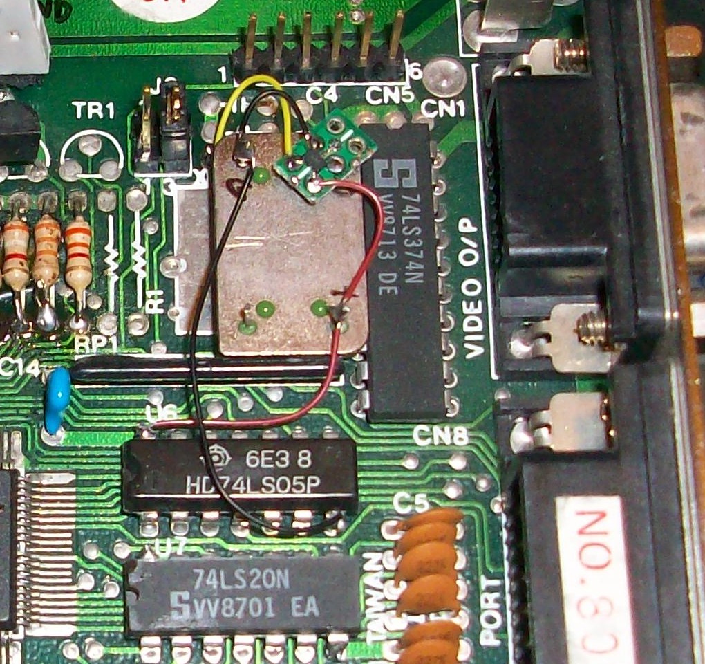
The CGA video card had an unpopulated space for a crystal, as well... I followed the traces and it seemed that there was a soldered-in wire where there could've been a set of jumpers to select either the clock signal from the ISA slots, or from the onboard (unpopulated) crystal's unpopulated circuitry... Since I didn't know what support components were necessary, and since the signal coming from the ISA slot was 0-5V, surely I could insert a crystal-oscillator with 0-5V swing, instead...
I dunno how it's possible, but the output from the crystal-oscillator wasn't strong enough... so I inserted a 1-gang 74AHC04... and even then the signal strength wasn't enough.
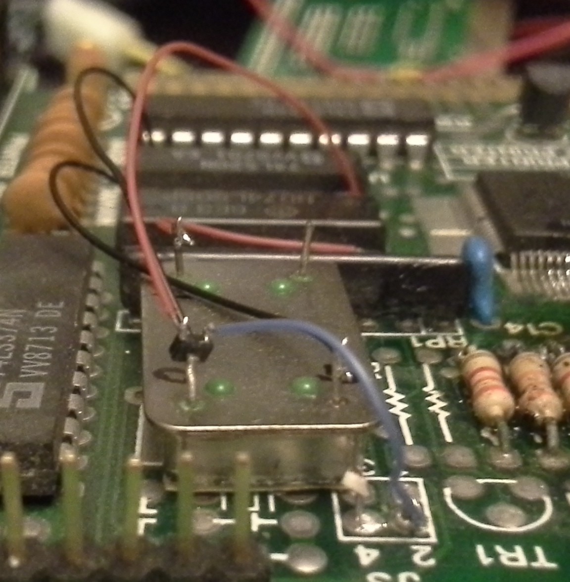
That was a bit wonky, and was only a temporary-experiment, and once I measured a strong signal output I soldered it up right-er.
You can see the newly-installed
jumpers to select the clock-source...
The result was *exactly* the same... there was a signal going to the TV, but it wouldn't sync, and was completely illegible.
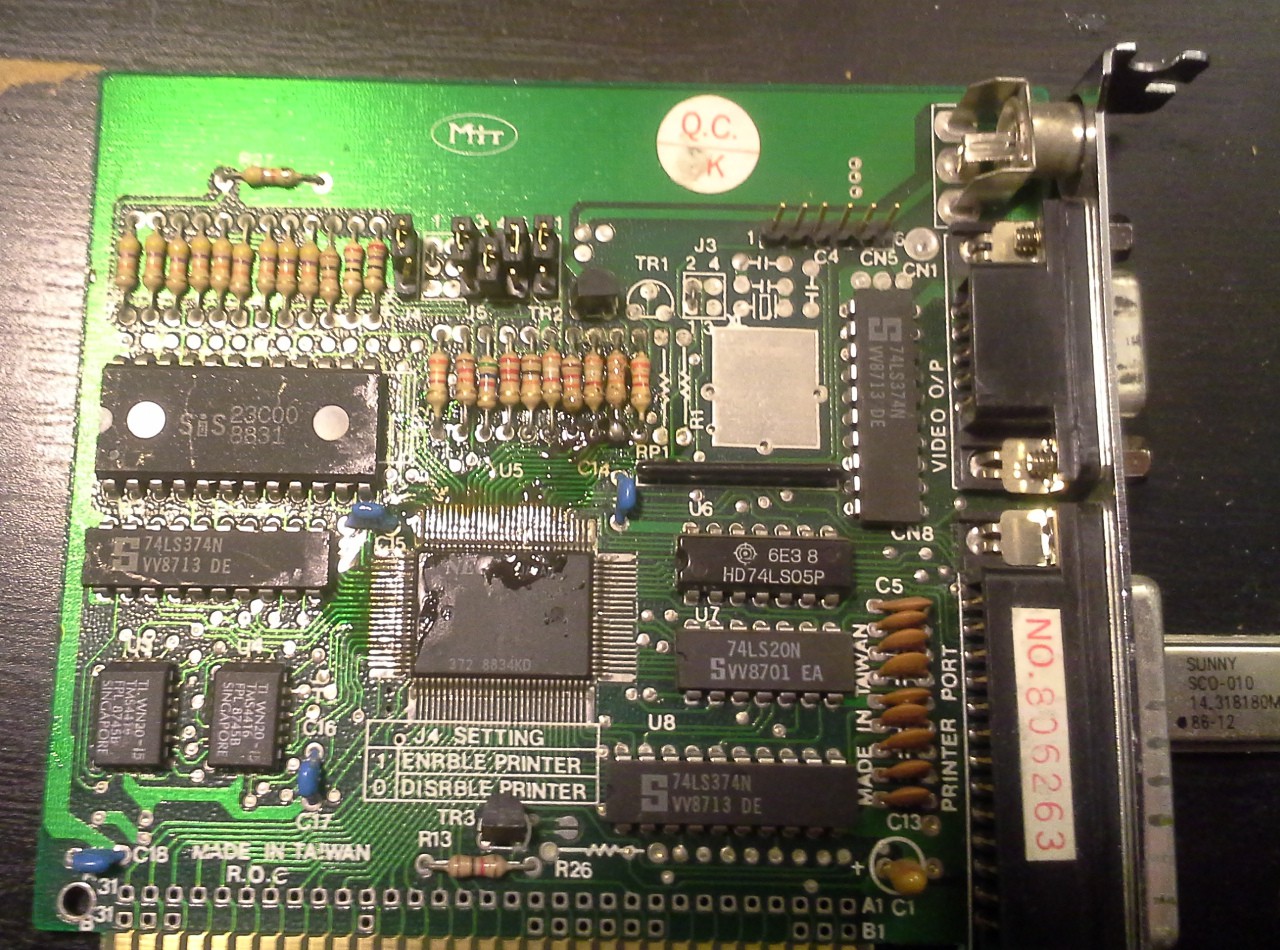
The board was nastily corroded around the "GPU", and the resistors above it, so I spent some time cleaning that up. The resistors were especially hard to clean, I just kept throwing a bunch of flux at it and scraping with the iron's tip. What I should've done was remove and replace them. But metering it out from the other ends of the traces seemed right, so they couldn't be the problem (for now)... right?
Still no change.
Finally I just gave up and started swapping random (unlabelled) jumpers on the CGA card, 16 possible combinations... But sure enough it worked... second try. Maybe it was set for PAL?
...
Stepping back, now that it's functional with a crisp picture, I try adjusting the capacitor, again, try the two different crystal-sources, etc... and... basically all that work was completely unnecessary... the (new) on-board crystal and capacitor did the job, once those jumpers were set. Weee! (BUT WAIT! My friggin' scope was showing 14.04MHz, no?! WTF?!).
But I'm leaving my deadbug crystal-oscillator hack, dagnabbit!
Now... the thing needs a floppy controller, so I dig one out that looks to be right for the system... It's a bit beat-up (stored as scrap-PCB), the battery-socket's been ripped-up, but otherwise nothing appears shorted or broken... Plug it in and... the power supply won't turn on. Fine, scrapped.
I've another idea I came across while digging through the boxes:
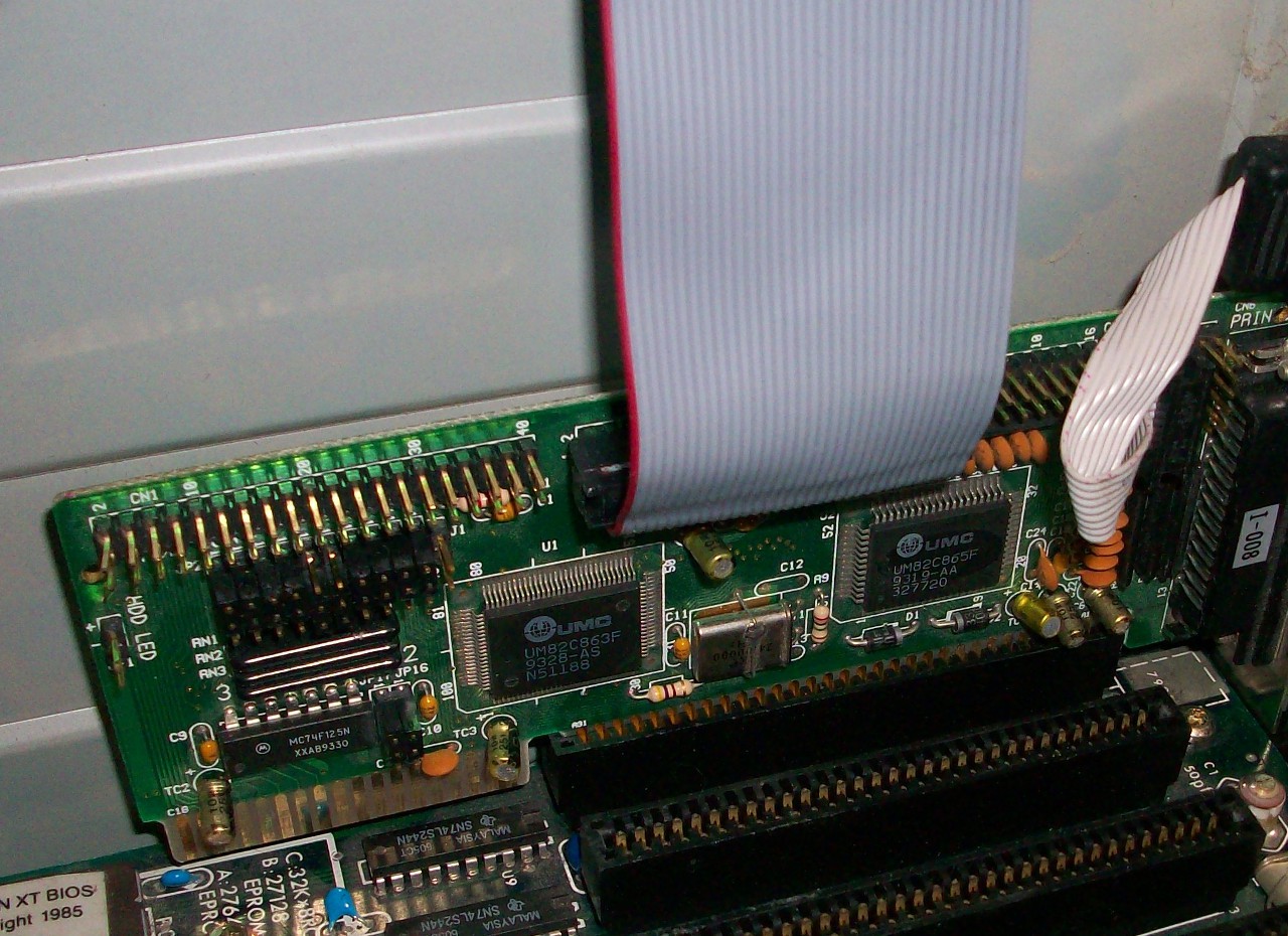
It's a multi-function card, I think from the 386, maybe 486-era. But I followed the traces on the 16-bit edge-connector, and they *only* go to the IDE connector! So, disabled the IDE controller, and... seems to work-ish. The floppy drive reads when it's supposed to, the parallel port was detected, etc.
So, now, the floppy drive... Now *there's* a multi-day endeavor, and I didn't really take photos of the nitty-gritty.
I only have 1.2MB 5.25inch floppy drives... And, apparently, the XT BIOS doesn't like those (it was designed to work with 360K drives). Long story short, one of the higher-quality TEAC drives in my collection has a *lot* of jumper-settings, and some pretty decent documentation online, as well. And, within that documentation is, in fact, some jumper-settings making mention of XT computers. So it should work, right? I tried everything, learned a ton about the floppy interface signals, and more... But never could get that danged drive to work.
So I went back to the original floppy-controller, the one with an edge-connector for the floppy-cable rather than IDC connectors... Yahknow, dang thing looks like it was meant for this system, and even has some labels that match those on the motherboard. I even managed to find an old archive of jumper settings and whatnot for boards like these "Total Hardware '99", even managed to figure out, through that, what brand made the thing and what model it was, despite its not having any markings... Turns out the problem with the power supply was simple, one of the bulk-capacitors right at the ISA connector had shorted-out... I just wiggled it until it broke off and it powered-up fine. But... still nogo with my 1.2MB 5.25in drive.
Finally I gave up and tried something that seems utterly-ridiculous, based on what I'd learned about the signals... something I'd read passingly on a forum, and dismissed as absurd. Allegedly you can connect a 1.44MB 3.5in floppy drive to an XT, and if you use 720KB disks, it allegedly will work.
Whelp. Sure enough... It works. I can't explain it, despite everything I'd learned about floppy-controllers and signals, about data-rates and spindle-rotations, nevermind bytes-per-track... but it works.
And, yahknow, I can write 720K 3.5in floppies in my friggin' USB-floppy-drive. Wee!
------
OK, so now I've a bootable system!
All I really needed to do was rewire the keyboard, switch the well-documented switch-settings properly on the motherboard, randomly switch around some undocumented jumpers on the CGA card, and believe something utterly-ridiculous I read on a forum. (Why does this feel a bit like the solution to MYST? Certainly playing that again would've been more fun than doing this!) Instead, at this point, I'd already invested well over a week and many sleepless days into the danged thing...
weeeee!
------
Oh, and the multi-function 16-bit ISA card works fine in an 8-bit slot, so that's pretty cool.
-----
So, now, I have this brilliant idea that maybe if I install a SCSI card, I'll be able to boot from a SCSI hard disk.
This ordeal... another "meant to be, right?" scenario. I plugged the thing in, and sure enough, during the POST procedure, the thing goes through its process of detecting drives. NICE!
Got a 1GB SCSI hard-drive erased and loaded up with most of my 8088-compatible software... oh man... I did this in another much-newer system I built, which I haven't even *begun* to talk about, here... I'll letcha look at those old logs, this was supposed to be just photos... Here's one from that log, wherein one of my newer pentium-based system attempts flat-out refused to work, and instead just stared back at me.
Anyways, loaded the thing up on a different newer system which was booting from that drive on the controller-card which was auto-detecting drives on the XT... but it wouldn't boot on the XT.
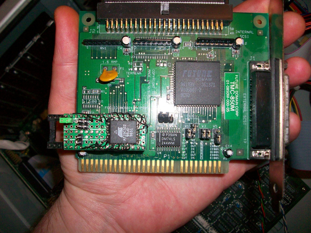
So, some forum post, and some pretty cool dude... apparently the newest ROM available for this SCSI card (v8.5, which I happened to have) doesn't work with XT computers, but v8.2 does. And that cool dude just happened to upload v8.2.
So, now... I've got to load an EPROM or something with the v8.2 ROM. I don't have a UV-eraser, at this point, so I built this adapter for a FLASH chip (shown in my universal-chip-programmer):

And then the ordeal with the chip-programmer... Actually it's a pretty cool story. I lost my chip programmer's "personality module" for programming [E]EPROMs a while back, much to my dismay... So it wouldn't program anything until I replaced it. I did a *lot* of unfruitful searching for a replacement long ago, so this time I wound-up emailing a guy who mentioned having this programmer in a forum-post SEVENTEEN YEARS AGO, and within two hours he sent me the needed information to recreate my lost module (no kidding).
That story is explained over at: https://sites.google.com/site/geekattempts/misc-notes/megamax-programmer
But suffice to say, I replaced the lost personality-module with a home-made one:
 And, at this point, I discover that my programmer has some blown transistors (WTF, how'd that happen?!) So, a bit of troubleshooting in there, and two transistor-replacements later, (and we're talking *days upon days*, at this point) we've finally got a programmed v8.2 ROM for my SCSI card to boot my PC/XT computer from a 1GB hard disk...
-----------
ALRIGHT!
At this point the whole thing's pretty much functional... But I've been running it as a mess of wires and PCBs strewn across my coffee table for weeks... Time to put it in a case... OF COURSE I didn't save the original case... that'd've been ridiculous... Who could possibly want an IBM PC/XT in/after the era of Pentiums?
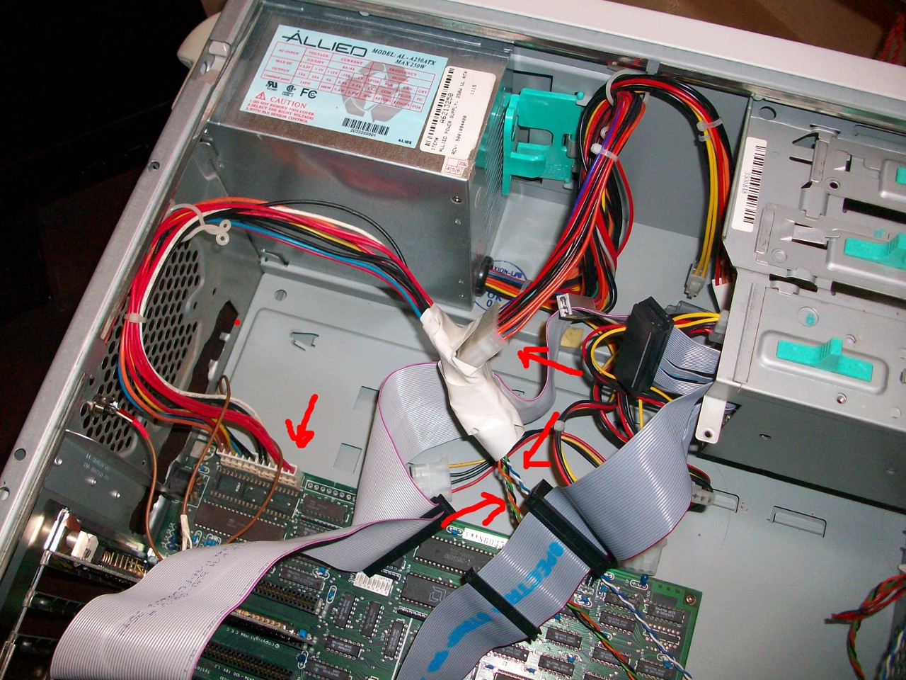
So, I've chosen an ATX case. And an ordeal with the power-supply... My original AT-style power-supply had cables which were too short. So, amongst the first things (besides drilling out the necessary holes, etc.) is to make a power-extension. But, yahknow, instead of actually making an extension, which would've been as easy as just using a bunch of wirenuts... I decide to use an ATX power-supply, instead.
Well, boy-howdy, that shoulda been easy enough, but instead it wound-up being an ordeal of several days. (also logged in past-logs).
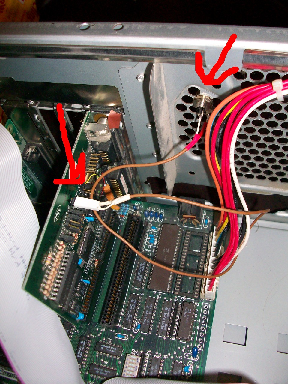
Now, ridiculously, this ATX case has only one LED on the front... a dual-color one for indicating both power and hard-disk activity. That's great! No... It's a common-cathode, and my hard-disk activity-output requires common-anode.
So, now... I've taken it even further, and decided to replace that LED with an RGB-LED WEEE! Now I can choose which color indicates power (green) and which indicates the hard-disk (Blue... OOOOhhhh blue-LEDs in a PC/XT computer!). And maybe even find a use for the red, as well. But, of course, my multi-color LED supply just happens to have been from the very beginning of the multi-color LED era... back when a single RGB LED cost nearly $6. And so it requires *two* blue LEDs (internal) to light up even remotely bright enough to be seen over the green... and even the green's not particularly bright... and the designer of this ATX case (who will remain unnamed) used a light-pipe system which doesn't really do a very good job of piping light... so basically all that work and it's barely even visible unless you're staring *right* at it, from a +/- 10 degree viewing-angle. Weeee! But, I suppose that makes it at least a tiny bit more period-accurate, anyhow.
Really, this was supposed to just be pictures...
Alright, next ordeal...
The stupid ATX case, again... The design of the bracket-mounts is like none other. Instead of using screws to screw the ISA/PCI brackets down, it has some sort of springy-lever which clamps them down. Seemed cool, at first. But turns out it's a bit faultily-designed. That springy-clamp-thing actually blocks the tops of the brackets. Which blocks my CGA card's Composite output. So now...
(Maybe I should build a light-pen!)
------
Now, a fully-functional PC/XT-clone in an ATX case with a blue LED and a 1GB hard disk... What on earth am I gonna do with this thing?
------
Tonight: Installed a ZIF socket in place of the BIOS ROM, and found another XT BIOS ROM in my old EPROM collection... So now I've the original "American XT BIOS" and a "Super XT BIOS" to mess around with. The Super XT BIOS seems to boot my machine just fine, and also shows RS-232 cards in the device-listing during boot (which the original didn't)... so that's cool. (Heh, wouldn't it be funny if it worked with 1.2MB 5.25in floppy drives?)...
Received a "germicidal" bulb to build a UV-eraser... So now the SCSI ROM is now a regular ol' EPROM... maybe I'll use that FLASH chip for my BIOS experiments.
---------
More in-depth writings on the ridiculous experience this has been:
https://hackaday.io/project/18868/log/50347-to-up
- "My home is Tore-Up!"
- Newer System Adventures, and conscientious-objection
- Findings on old hard drives
- Floppy ordeals
- CGA WEEE!
- Finding that keyboard "meant to be!"
- Rearranging led to a new workbench! (which is now covered with storage)
https://hackaday.io/project/18868/log/50426-eepromer-adventures-and-more-realistic-goals
- "and it *still* didn't occur to me that I have an EEPROM-programmer, in my possession."
- the "miracle" communique for my personality-module replacement
- (more realistic goals for the *actual* project)
https://hackaday.io/project/18868/log/50648-it-boots
- "(Can it be called a "machine" if its guts are strewn across a table?)"
- "Hack" to repurpose a USED EPROM without a UV-Eraser
- Discovery of EEPROMmer's dead transistors
- "debug.exe"
- 736KB? Screw 640!
https://hackaday.io/project/18868/log/50774-casing-ttl-fail
- Reclaiming my coffee table - An ATX case
- ATX power-supply decision
- Simple Flip-Flop Circuit
- Pull-Downs, CMOS-expectations, and old-school TTL = fail
- Really, quite a lot about old-school TTL... sheesh
- This shoulda been easy!
https://hackaday.io/project/18868/log/50780-open-collector-fail-the-atx-power-switch-saga-continues
- Adding a NPN transistor to the output, to make it "open-collector"
- Installing a PNP by mistake
- Learning a ton! Didja know a BJT can be turned on by VCB rather'n VEB?
- This shoulda been easy!
- Shoulda left it, it actually worked with a PNP in an NPN's place, but wasn't "normal".
Discussions
Become a Hackaday.io Member
Create an account to leave a comment. Already have an account? Log In.
You should get a better power supply - Allied/Deer is notorious for being poorly built and taking out components plugged into it.
Are you sure? yes | no