 Eric Hertz
A nice surprise, that I'll save for future-endeavors:
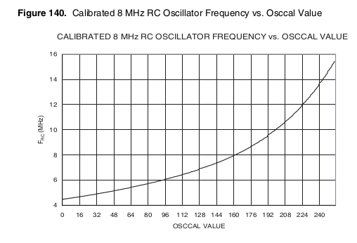
I figured OSCCAL would allow adjustment of the 8MHz (nominal) R/C oscillator with only a small variance in either direction, but here it seems I could adjust it to (roughly) Three Times the 8088 Bus Clock (14.31MHz)!
I've vague ideas of how to fine-tune that... maybe using an 8-bit timer/counter, and counting external 4.77MHz clocks until it overflows, counting internal clocks at the same time, and adjusting the OSCCAL value until we get ~768 internal clocks between timer-interrupts. That'd probably be accurate-enough... Especially if I have a routine that waits until an edge is detected before starting each bus-transaction.
It's entirely plausible it'll sync-up somewhere mid-clock, and that's something I'll be pondering. Maybe it means we can only, reliably, execute two timing-sensitive instructions per bus-clock... I dunno.
---------------
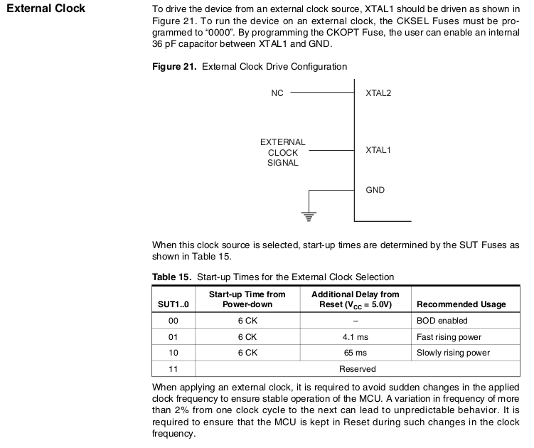
External-clocking at 4.77MHz (1:1 AVR/8088 clocking) also seems feasible (and would certainly be easiest for these early experiments):
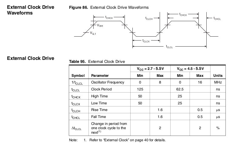
Note, no mention of duty-cycle. (and, in fact, the drawing isn't even close to 50%!)
(because, the 8088's clock is 4.77MHz with 33% duty-cycle).
-------------
Finally: I think I've managed to whittle down the bus-transaction such that with 1:1 clocking, the AVR should be able to keep up within the requirements of external memories and I/O (and the 8288). (Though, NOT, the 8087 and DMA controller... which I'll leave uninitialized for now).
#define S20_INT_ACK     0x0
#define S20_READ_IO     0x1
#define S20_WRITE_IO    0x2
#define S20_HALT        0x3
#define S20_INSN_FETCH  0x4
#define S20_READ_MEM    0x5
#define S20_WRITE_MEM   0x6
#define S20_PASSIVE     0x7
#define S20_IDLE    S20_PASSIVE //my own naming...

void bus88_write(uint8_t s20, uint32_t address, uint8_t data)
{
   //////
   // 4.77MHz = 209.6ns
   //  clock-high = 33% duty-cycle = 69.88ns
   //  clock-low =  66%            = 139.76ns

   //////
   //AVR latches inputs on the falling-edge
   // 'in R17, PINA' is valid *half* a period after, or in the *next*
   // clock-cycle
   // (and R17 contains the value at the rising edge of the one following)
   //
   //AVR latches *outputs* on the rising-edge *after* the instruction
   // completes.

   //Note, all AVR-OUTPUTs, here,  are expected within ~20ns after bus's
   //       Falling-edge
   //      all AVR-INPUTs, here, are expected within ~20ns after bus's
   //       Rising-edge

   // So, maybe a 7404, or something, could be found with ~20ns
   //  propagation-delay, and wired between the bus-clock and the AVR
   //  clock-input.
   //  Or, chain a few inverters in series.
   //  (Believe it or not, this was once a go-to method for synchronizing
   //   digital logic... Sometimes you'll even find a production-board with
   //   a chain of inverters and a clock-signal hand-wired to a point
   //   somewhere inbetween)

 //### Bus is idle (assumed) ###

   //So, it should be OK to prep our Address bytes
   ADDR1916_PORT   = (uint8_t)(address>>16); //assuming bits 20-24 are 0
   ADDR158_PORT    = (uint8_t)(address>>8);
   ADDRDATA70_PORT = (uint8_t)(address);

   //Begin the Bus transaction
   //Per 8288:
   // This should happen between tCHSV after _|¯ and tSVCH before next
   // tCHSV = Status Active Hold Time >= 10ns after _|¯
   // tSVCH = Status Active Setup Time >= 35ns before next(?!) _|¯
   // So, basically, somewhere around T1's entry ¯|_
   S20_PORT       = s20;   // OUTPUT, AROUND: ¯|_

   // The 8288 will bring ALE High...
   //  Either from the clock ¯|_, or from S20 ¯|_, if after clock

 // ¯|_  ### T1 ###
   // Normally, Addresses would be setup here,
   //  but we're fudging the timings a bit...
   //  They've already been done.
   // The 8288 will bring ALE Low in 4-15ns after _|¯

   //Nothing to do?!
   // Gotta keep the timing aligned...
   asm("nop;");

 // ¯|_  ### T2 ###
   // "T2 is used primarily for changing the direction of the bus during
   //  read operations" -- 8088-CPU.pdf
   // The 8288 will bring /AMWC, /AIOWC, etc. low in 10-35ns after ¯|_
   //  for "advanced" (early) write-signals
   //  (Not really important to note here)
   // FOR READ: This is the same time where /MRDC, or /IORC occurs
   //TODO: Should probably make sure the ALE pulse is recognized
   //  by other devices, before we change AD7:0
   //  BUT: it's already been half a clock-period, right?
   //  So should be fine...
   //  ALSO, if we meet/exceed the 8088's minimum timings, here,
   //  then it should be fine.

   //Put the data-to-write on the port
   //8088: TCLAX ¯|_ -> A19:16 -> S6:3 Address Hold >= 10ns
   //      TCLAZ ¯|_ -> AD7:0 -> Float (READ) Address Float Delay 10-80ns
   //      TCLDV ¯|_ -> AD7:0 -> Data (WRITE) Address Valid Delay 10-110ns
   ADDRDATA70_PORT = data;  //OUTPUT: >10ns AFTER ¯|_


   //Technically: A19:16 -> S6:3 is also supposed to happen here
   // but for now we're not using the 8087, nor DMA, so should be OK(?)

 // ¯|_  ### T3 / Tw ###
   // The 8288 will bring /MWC, /IOWC, etc. low in 10-35ns after ¯|_
   //  for *non*-advanced/non-early write-signals

   //It's not possible to read the READY signal, test it, then jump
   // all in a single AVR cycle
   //Thankfully, it seems the 8288 is triggered only by /S2:0
   // And the processor is the only thing that pays attention to READY
   // And, nothing else is expected of the processor outputs during T3/Tw
   //So, we can insert our own "wait-states"
   // in the form of internal processing-time, then return /S2:0 to "idle"
   // when it's complete

   //According to one diagram (showing READY being sampled!)
   // READY should be sampled with ¯|_ entering T3/Tw
   // in 8088-CPU.pdf p10
   //According to another diagram, READY should be sampled with _|¯
   //!!! TRYLCL could be up to 8ns *into* T3 (but not Tw)
   // TRYHCH setup time > 118ns to _|¯ mid T3/Tw!!!
   // TCHRYX hold-time > 30ns after _|¯
   // in 8088-CPU.pdf p23
   //Confusing, but the actual *timings* suggest _|¯
   //
   // OK, sample READY on _|¯
   while(!(READY_PIN & READY_MASK))  {};  //INPUT: <30ns AFTER _|¯

   //NOTE That we'll be in a later Tw, at this point... weeee!
   //Indicate that we're done with wait-states, and ready to enter T4
   //8088: TCLSH Status Inactive Delay: after ¯|_ 10-130ns
   S20_PORT = S20_IDLE; //OUTPUT: >10ns AFTER ¯|_

 // ¯|_  ### T4 ###
   // The 8288 will bring /IOR, /IOW, etc. high within 10-35ns of ¯|_
   // We're not reading, so we don't need to sample ADDRDATA_PIN
   //  But, for READ, it should be done quickly after ¯|_, or maybe before
   // 8288 timing shows Write Data Valid as acceptably valid after T4
   //  Same likely goes for A19:8... (whew!)

   //Nothing to do?!
   asm("nop;");

 // ¯|_  ### BUS IDLE ###
   // WARNING: This is NOT compatible with DMA and 8087!
}
In case you didn't catch that, lemme take out the majority of the comments:
   ADDR1916_PORT   = (uint8_t)(address>>16); //assuming bits 20-24 are 0
   ADDR158_PORT    = (uint8_t)(address>>8);
   ADDRDATA70_PORT = (uint8_t)(address);

   S20_PORT       = s20;   // OUTPUT, AROUND: ¯|_

   asm("nop;");

   ADDRDATA70_PORT = data;  //OUTPUT: >10ns AFTER ¯|_

   while(!(READY_PIN & READY_MASK))  {};  //INPUT: <30ns AFTER _|¯

   S20_PORT = S20_IDLE; //OUTPUT: >10ns AFTER ¯|_

   asm("nop;");
SO MUCH SIMPLER than the earlier expectations, wherein I thought it would be darn-near impossible to get it running with a 4:1 AVR clock. And, here it should work with 1:1.
------------
I've still gotta wire this thing up, and the cat's being deprived, so it may be a while until I get a chance to check this out.
Thankfully, READ is pretty much identical, (and has been accounted-for in the comments)...
And it'd be pretty easy to e.g. use the AVR's UART (or just an LED) to indicate whether writes/reads to a low memory-address verify correctly. (A bit of a shout-out to comments in earlier logs, suggesting using the AVR's peripherals... I'd been planning to do some CGA video-output for my first "hello-world" but that's way overboard)
--------
And... the 8515 might just work with only a few pin-relocations, it's got a very similar pinout to the 8088.
Discussions
Become a Hackaday.io Member
Create an account to leave a comment. Already have an account? Log In.