 Eric Hertz
The circuit from the last log is now wired-up, installed on the motherboard, and being tested with various programming...
Nogo, so far.
First, I tried to do it "blindly" with just an LED to indicate if data written to the DRAM on the motherboard was read-back incorrectly. The LED lit immediately on power-up.
After all that studying of the bus, I was pretty certain that'd've worked. So I fought with it for a while before resorting to a more reliable debugging-method.
On the plus-side, the pull-up resistor TTL->CMOS level-conversion seems to be doing the job, at least for the clock-signal (which has amongst the most strict input-level requirements).
I didn't have a 74S04, but I did have a 74F04, with similarly-spec'd propagation-delays. I installed a jumper-system so I could drive the AVR's clock from the inverter-chain after either one, three, or five inverters. (From timing-diagrams, I estimated that I need an inverted clock, and a slight delay, on the AVR's clock).
I was worried the AVR wouldn't like the 8088's clock, which is 4.77MHz, but with a 33% duty-cycle. But it doesn't seem to be complaining about that.
For Reset, I originally planned to use the sixth inverter, but it turns out my Schottky diode supply is quite limited (as in almost non-existent). The AVR's Reset signal is active-low, while the system's is active-high. Also I need to isolate the AVR's reset from the system reset, in order to use the in-system-programmer. To be within the AVR's VIL-max specs, a regular ol' diode (with a drop of about 0.65V) driven by a TTL chip with a VOL-max of >0.45V wouldn't do. I didn't even bother soldering that up. Instead, I followed a suggestion from a comment in the last log, and used a 2N2222 NPN resistor and a pull-up. I haven't tested that, as it looks like, from the schematics, the only source of system-reset is upon power-up... and the AVR's definitely running.
(Kinda ironic the PC/XT's active-high reset signal is controlled apparently-exclusively by the "Power-Good" signal. The point of Power-Good is to keep the system in reset until the power-supply has stabilized at ~5V. But, if the power-supply is "not good" at, say, 3V, then the output of the Reset signal couldn't be any higher than 3V, and technically that's not high enough for the active-high 8088's Reset Input's VIH-min. Of course, that VIH-min is assuming the chip is powered by 5V, and I'm sure they designed it to function.... but, an active *low* reset input makes a heck of a lot more sense to me.)
Since I'm not getting write-read tests to the DRAM to verify, I decided I needed to see what I was reading-back... I followed some other advice 'round here and opted to make use of the AVR's peripherals/software, rather than relying entirely on the system's peripherals... (I wouldn't be able to use the RS-232 ISA card to output data, if I can't write data to the ISA bus!).
So loaded up my usual AVR test-software, which includes a bitbanged serial-port on the ISP header. (I use bit-banged rather than the USART peripheral, because it can make use of the ISP header pins, rather than some random pin on another port that, in this case, is used for the Address Bus).
The result? Read-back from every address-location I've tried results in 0xff. I even tried reading data from the BIOS ROM, with the same results.
I've done a bit of "finagling" with the 8088's bus-timings to make this system possible... Including adding a *significantly long* and "artificial" "wait-state" when reading the actual system-READY signal (which requests wait-states). Removing the READY test and inserting various numbers of NOPs, instead, gives the same result. EXCEPT, when I use only one NOP (which, I think, should meet the bus-timing when no wait-states are requested, which *should* be the typical case). In that case, I read-back the low address-byte... (The low address-byte and the data-byte are multiplexed on the same port). So, at the very least, it would seem that the AVR is reading back the port correctly.
(Note that the AVR's inputs are delayed through a latch-system, so it may, in fact, be reading back the actual address written to the port, rather than, say, reading a floating-bus being slowly pulled up through resistors).
(Oh hey! Reading-back 0xff indicates that the pull-up resistors on the address/data port are doing their job!)
-----------
Anyways, not getting *anything* back from the ROM is plausibly indicative of something other than a problem with wait-states. (AS I UNDERSTAND: The READY signal *should* be active only when the device is actually ready to output data. And the output data *should* be held until the /RD signal is deactivated. And the /RD signal should only be deactivated after the CPU indicates it's done with the bus transaction... So if I insert some extra wait-states, via NOPs or via the delays caused by reading the READY signal, testing it, then branching, the data-output should still be valid until the /RD signal deactivates, which shouldn't happen until after I've read the data and indicated that the wait-states are complete.
Oy, long explanation to say, I think [mis]communication with the 8288 bus-controller might have something to do with this not functioning... The 8288 generates the actual /RD signal. And, the fact I'm not getting any data back (except the address written to the address/data port in the one case) suggests that the 8288's not generating a /RD signal.
And alllllll that to say... I should probably dig out the oscilloscope, and probably should look more into the schematics, as well.
So I should probably move this off my coffee table, before my apartment turns into the "to' up" mess it did last time... with 'scope on the couch, cat sleeping under the TV, and me sleeping upright on the remaining couch-space. Which means I should probably do some dishes... and some other cleaning. Klotski, much?
--------
Oh, and... There's this recurring *feeling* that maybe I'm just not initializing the system properly... But, remember, (as I understand from the schematics) the system-reset is controlled exclusively by power-up. Or, at the very least is *not* controlled by the 8088. The 8088 *has to* get *every* instruction from the bus, *immediately* after power-up-reset. Thus, immediately after power-up reset, the system *must* be initialized-properly to allow the CPU to access the ROM (DMA controller can't be interfering with bus transactions, due to not being properly-initialized, etc).
So, maybe, considering the only source of resets *after* power-up-reset is software-based (and thus controlled by the CPU, which must get its instructions *to* reset *from* the bus), there's no chance that, e.g. a software-reset could occur in the middle of a DMA transaction (or other device *using* the bus)... So, what I'm getting at is that there's a *slight* possibility that the AVR's exclusive reset-input (e.g. driven by the ISP) could allow it to reset at *any* time, rather than in response to a bus-read (of an instruction). So, it's *plausible* that the bus could be in an unknown state during an AVR-reset. OTOH, so far I haven't configured any other devices to use the bus, and, again, those devices *must* be power-up-initialized to *not* use the bus, so it should be that every device remains in their power-up-initialized state... And, again, whatever that state is, it must be conducive to the 8088's being able to immediately retrieve its first instruction from the ROM... Thus, I shouldn't have to initialize anything, nor cause a system-reset whenever I reset the AVR... right?
I certainly shouldn't have to respond to interrupts, nor even the Non-Maskable-Interrupt before interrupt-handlers have been loaded from the bus. ...
Hmm, I did leave some control-pins floating... Request/Grant...? This one's bidirectional. Hmmm... (nope, schematic shows it pulled-up on the motherboard).
Heh, don't trust the schematic:
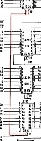
The bottom chip drives the "NMI Enable" signal...
Yep, need to grab the 'scope.
And not only don't trust the schematics because there's obviously an error (and maybe more)... but also because this is a *clone* motherboard, rather than an IBM original.
(heh, this was just going to be a couple lines saying essentially "it's soldered-up, programming, but doesn't yet work")
Discussions
Become a Hackaday.io Member
Create an account to leave a comment. Already have an account? Log In.
Keep at it, I want to see an AVR running DOS.
Are you sure? yes | no
LOL I'll keep at it, but the probability of its running DOS is very low.
Implementing 300+ instructions doesn't sound fun. But, of course, it is floating 'round the back of the mind. Your new log:
https://hackaday.io/project/2056-cat-644/log/52699-virtual-instruction-set-candidates
gave me a bunch of ideas for minimizing that...
Interestingly, someone just emailed me claiming to have found a modified version of Fake86 running on an AVR by a fellow named Mike Chambers (I haven't looked it up yet). The emailer says he ported that to a PIC32MZ and it's close to emulating 4.77MHz. So, DOS on an AVR may already be accomplished!
Are you sure? yes | no
Have you seen 8086tiny? if the memory read and write is properly rewritten (instead of the large mem array it creates), I think the code is small enough for an AVR. It's in C, so it might not be super fast.
Are you sure? yes | no
@Mark Sherman wow, 4KB of source-code! Also emulating all the peripherals!
Are you sure? yes | no
Uh oh. I still hoped for happy end.
This needs some logic analyzer, like 32 or 48 inputs wide.
Are you sure? yes | no
hahahahaha... you're so right. Would yah believe I hadn't even thought of using a logic-analyzer? And the friggin' thing's sitting on my desk right between my keyboard and monitor.
That guy's still a ways off, so I'll see what I can do with a 'scope first... Though it would be a great excuse to switch-gears back to that 'thing,'
Are you sure? yes | no
Yes, scope is especially good for first round of debugging, where, for example, you may have non-valid logic levels, which your LA may "understand" differently than the debugged hardware. So, everything may look OK for your LA, but not for your device. Anyway, good luck with this one.
Are you sure? yes | no
@jaromir.sukuba, indeed regarding voltage-levels. But a lot more can be done with a 'scope, alone... if that's all you've got.
E.G. If the 8288's not outputting anything, or ends the procedure before the AVR, that's a pretty decent indicator and can easily be seen with two 'scope probes. And at 4.77MHz, I think I can even use my slow old 'scope's digital/storage-mode! Weee!
(Edit: Just Barely! 4.77MHz is *just barely* usable on my 1980's 'scope in digital mode. I think I'm getting about 4-5 samples per clock cycle.)
Are you sure? yes | no