 Lauri Pirttiaho
A Weller WD1 soldering station controller was found in a refuse pile, abandoned apparently because some of the LCD segments had failed. Googling for a fix or spare parts revealed the LCD display isn't anymore available and there were no repair case reports for this problem. For other problems like blown fuse, failed TRIAC, re-flashing the firmware, some. For the LCD problems someone proposed replacing the driver, but in this case, that was not the problem. The driver was fine, the LCD not.
Having some cheap microcontrollers and character matrix LCD modules around, thought replacing the original display with an emulated one might be a viable undertaking.
For the emulated display one needs to choose the point of capturing the input to the display from which on the behavior is emulated. Here the alternatives are before or after the display controller. Of course, one could also connect the display directly to the main controller and rewrite its FW. Can do, but it would likely invalidate the existing user's manuals and overall, be much more involving a project than just replacing the display.
Taking the input to the emulation after the display controller involves much larger number of signals (40: 3 back planes and 37 segment groups) than before it (2: I2C SCL and SDA). The choice is clear.
The display controller is NXP PCF856CHL, an I2C connected chip for driving up to 4 back planes and 40 segment groups. As the data sheet is readily available, no reverse engineering was needed. Just implementing the same I2C protocol as the original chip's was enough. This chip is nice in a way that it is write-only device. That simplified the I2C slave enormously, as responding to reads is more complex than just accepting a stream of writes.
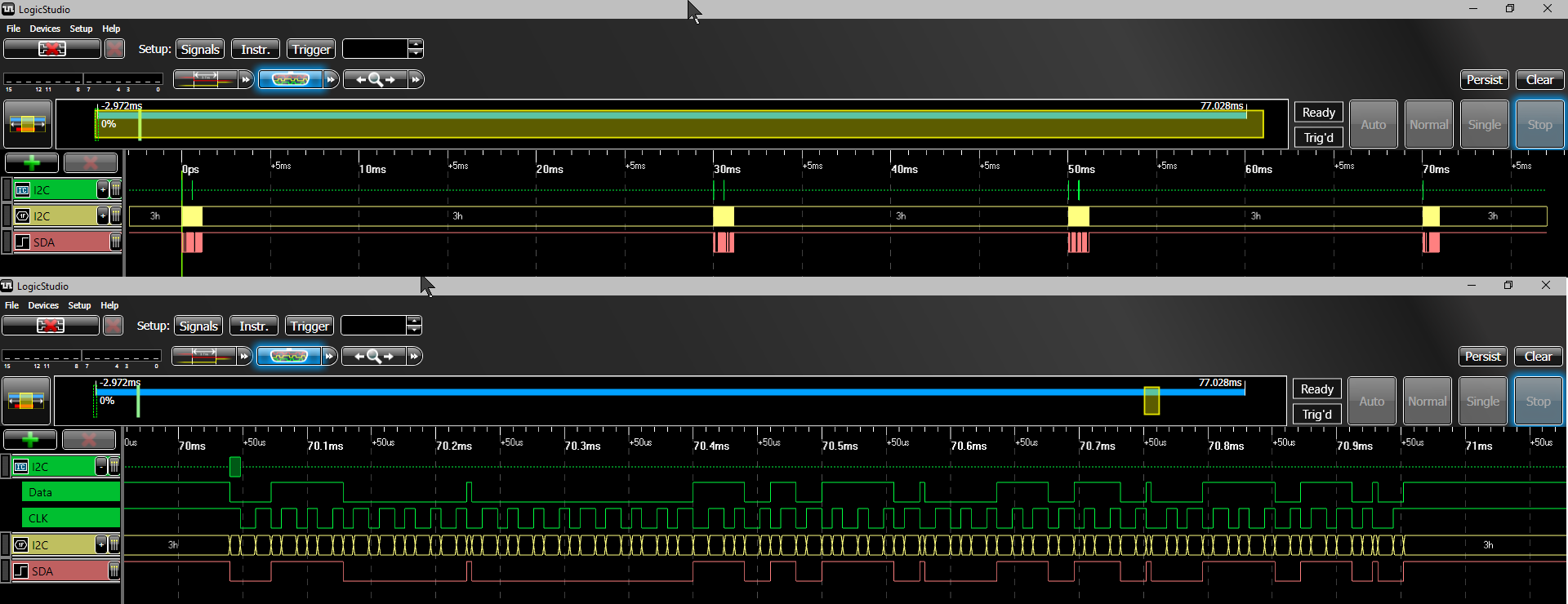
The controller writes blindly segment states in bursts of 2-4 bytes (16-32 segments) every 10-30 ms. Apparently there is a "screen buffer" in the main controller and the segment bits are taken from there with a timer-driven I2C writer process.
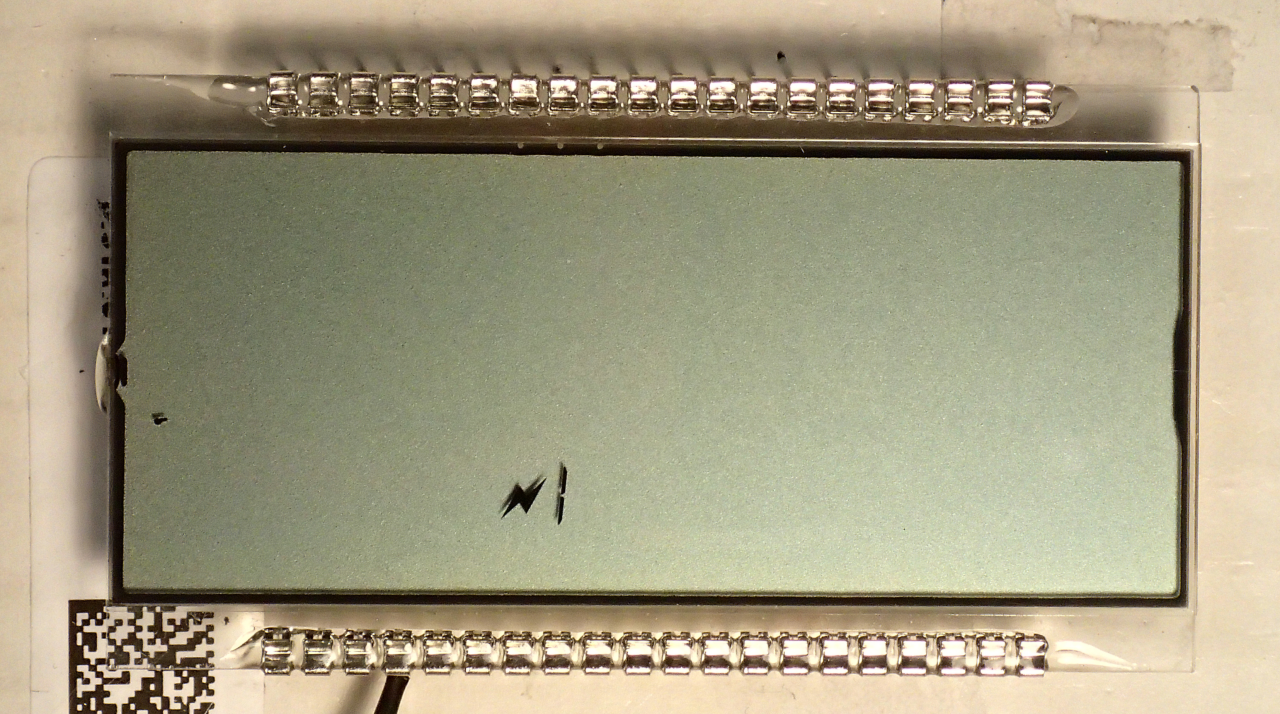
The LCD glass is another kind of issue, especially that the one at hand was partially broken. The controller data sheet describes exactly what back-plane - segment group pairs each bit written to it will control. The case for reverse engineering is to figure out the segment group and back-plane assignments.
Activating a segment group that was still connected to the pin was easy: just connect some static charge to the pin.
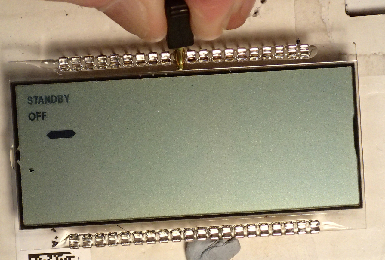
For a segment group no longer connected to the pin one needed to reach to hopefully still conducting part of the ITO trace from the pin to the LCD cell.
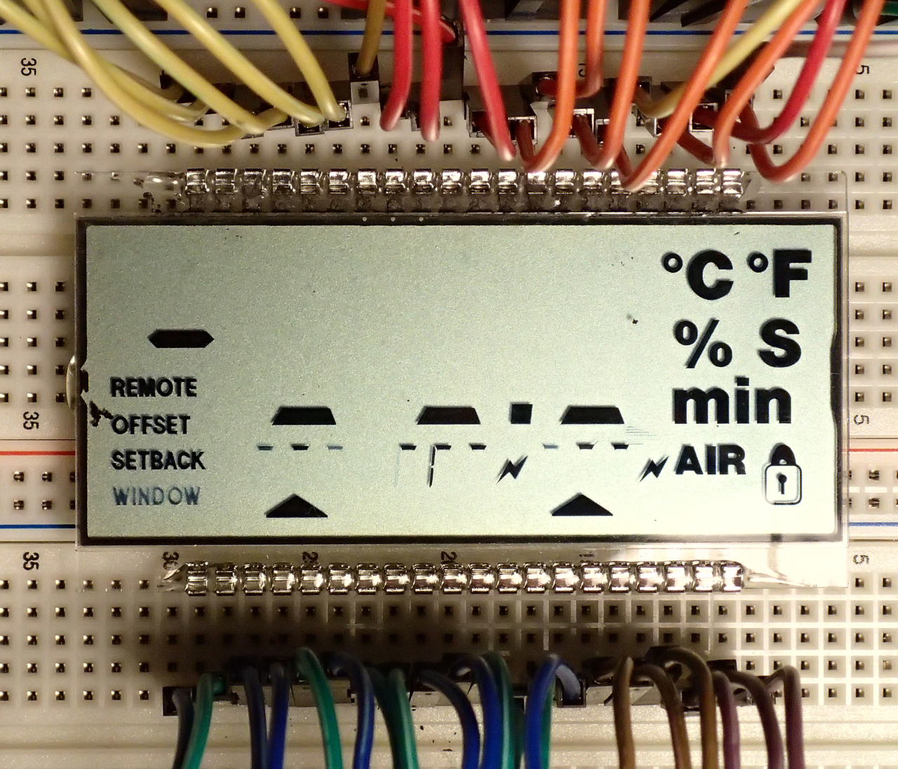
Activating the whole backplane groups appeared to be not possible. Therefore, repairing of the ITO traces was attempted, with a graphite paste made from graphite dust filed from a pencil core and using rubbing alcohol as the vehicle. No binder was used to make it possible to wash the paste away if needed. (The paste-repaired pins on the top side.) This repair is temporary. The graphite paste will not work for a longer time.
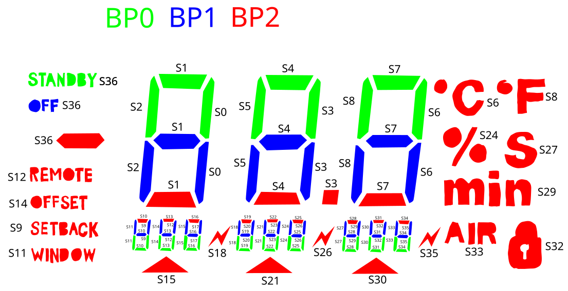
That actually turned out to work quite well. Despite some missed activations and misactivations eventually revealed everything that was needed to draw the map of the LCD glass.
After all needed information was gathered the next step was to choose components and make a replacement strategy. The common character matrix LCD module needs minimum of 6 pins and if one wants to use the RnW signal and read the status instead of writing blindly with long enough timings, 7 pins. I2C needs 2 pins. So it seems a 14-pin microcontroller (power and 12 I/O pins) should suffice. As a short tube of PIC16F18326 microcontrollers in SO-14 variant were at hand, that was natural choice. 16 k instruction FLASH and 2kB RAM should be enough.
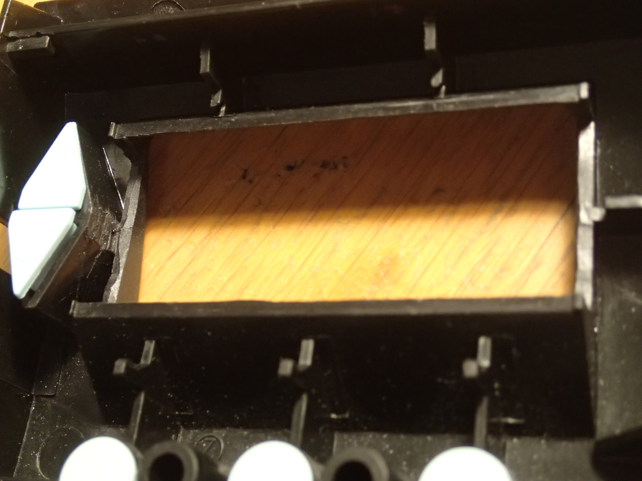
The next step was to carve (with a 9 mm snap-off blade knife) the front panel so that the thicker LCD module would fit in the place of the thin LCD glass. Also the module was slightly modified by bending down the bezel holding tabs that fasten it to the module's PCB.
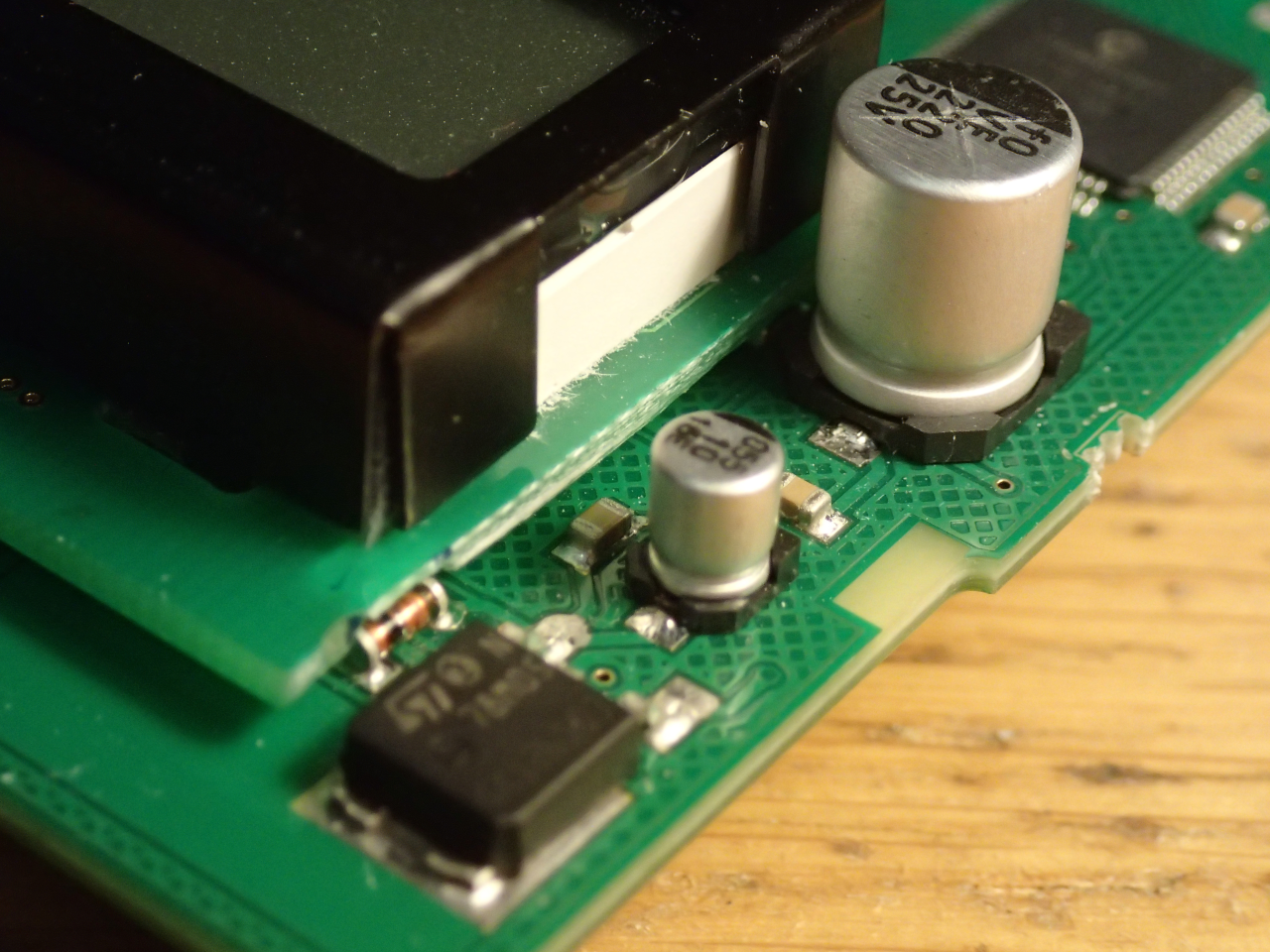
Also the module had to be cut a bit shorter to fit between the tactile switches at the right and the regulator caps on the left side of the space where the LCD glass had been.
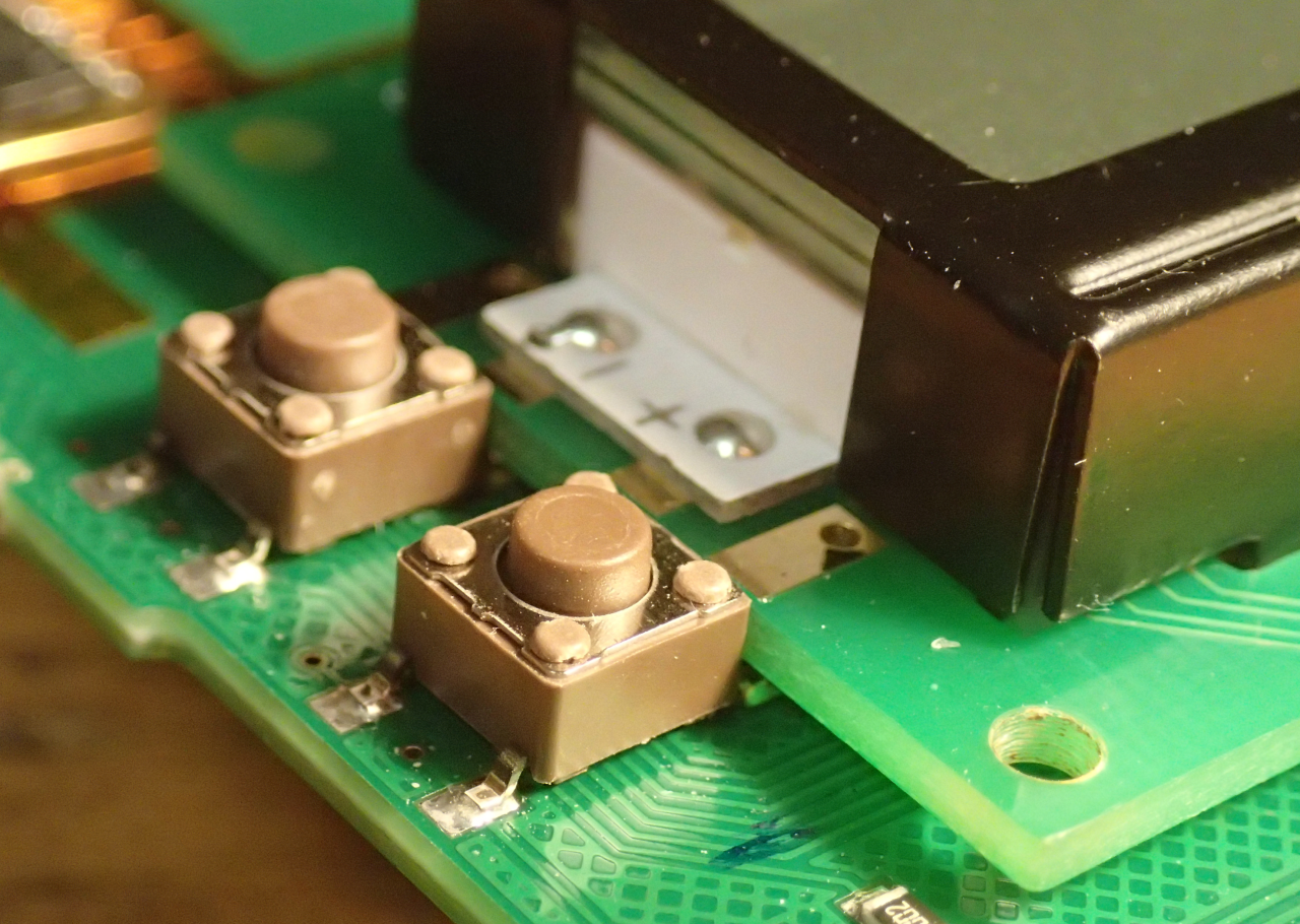
The bending of the bezel tabs under the module also made the mounting low enough so that the up/down buttons would work correctly. The module was fastened to the control board with Bison Montage Kit Extreme Grip double sided tape (before cutting this tape with scissors, put a strip of adhesive label backing sheet to the side which does not have it, or else the tape sticks to the scissors extremely strongly).
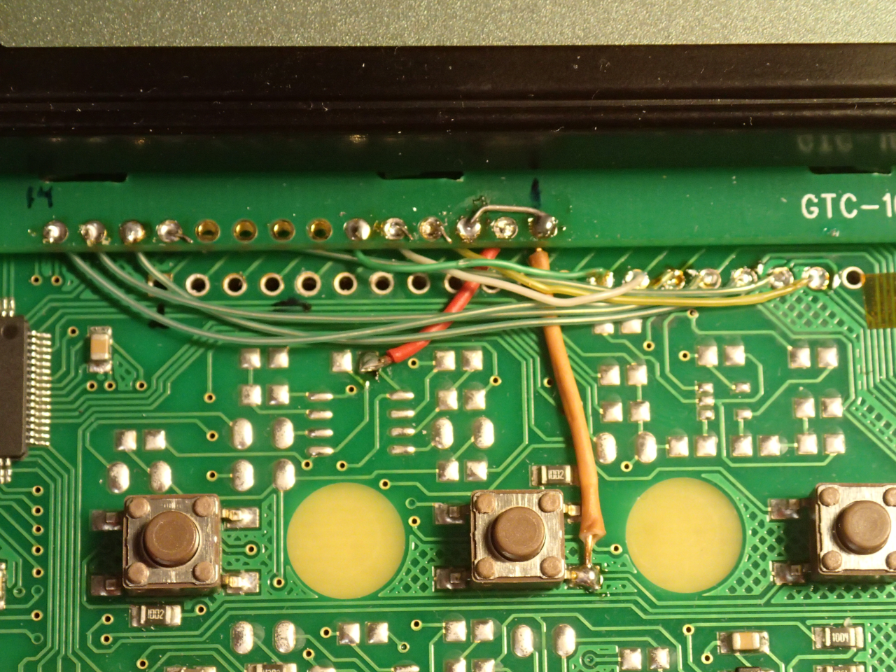
The LCD panel was wired to a selected set of pin holes of the original LCD glass in a way that the microcontroller could be placed into the place where the LCD controller had been and the PCB traces between these two sites could be used to wire the microcontroller to the LCD module.
The ground and +5 V were taken from nearby points on the control board. The contrast setting voltage Vo was tied to ground as the module used GTC-16026 has the nominal LCD voltage of 5 V. For other modules a resistor (VLCD < 5V) or a charge pump (VLCD > 5V) is needed. (A suitable charge pump can be made from a 74LVC2GU04 and two diodes, two capacitors and a resistor.)
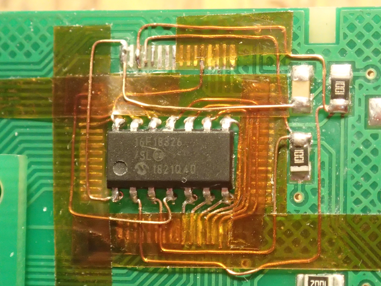
The microcontoller was fastened with two-sided tape (not Bison Extreme this time) to the place from which the LDC controller had been removed (with hot air using QFP nozzle) and wired to the traces connected to the LCD module, to the two I2C pull-up resistors and to ground and +5V. The multiple layers of the wiring were separated with strips of kapton tape.
The five lines for PicKit3 connector also reuse PCB traces from the LCD controller site to the LCD glass, now on the top of the glass. For debugging purposes also the I2C signals were routed to two pins to which wire eyelets were soldered for easy probing.
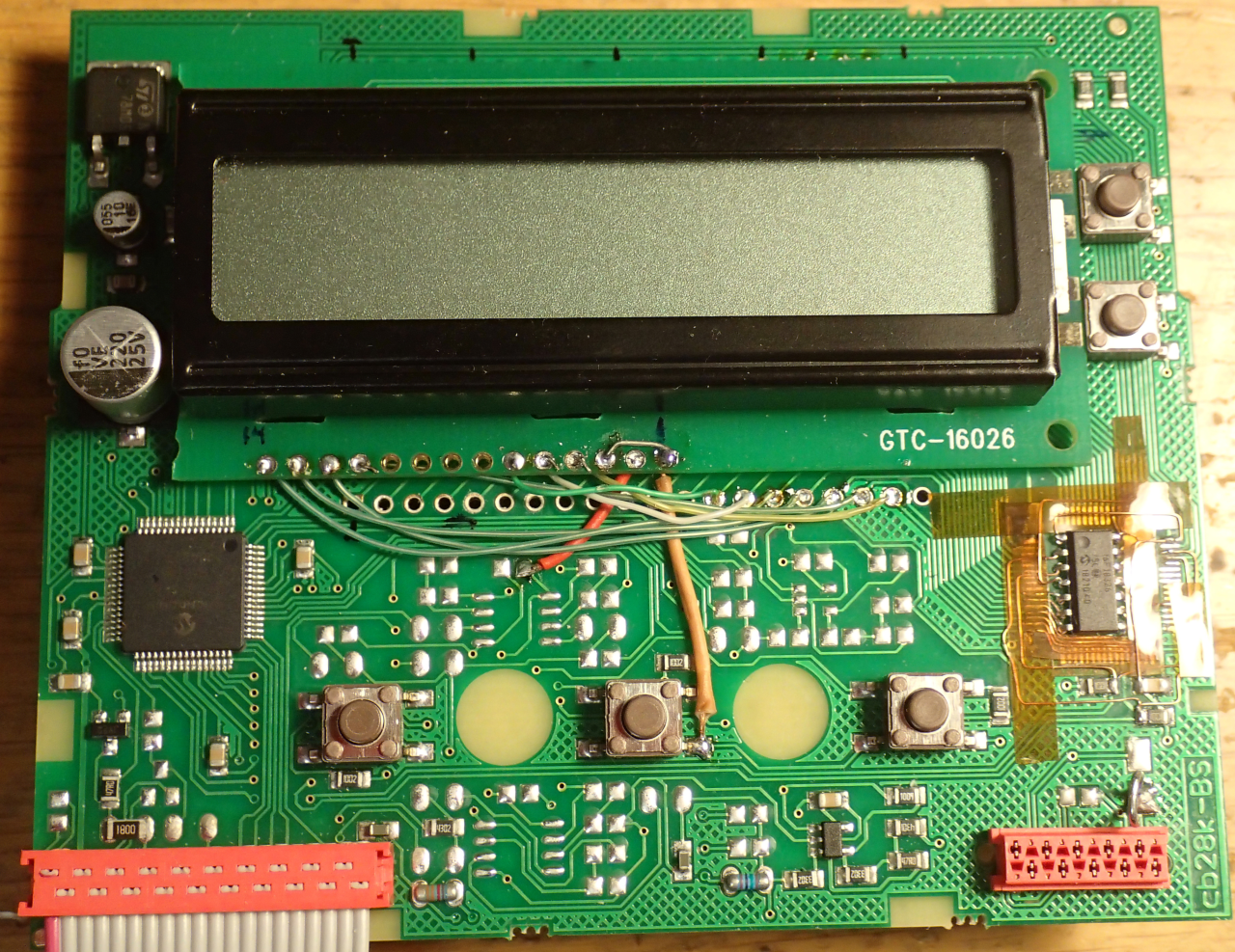
That completed the control board modification.
Writing the display emulator firmware for the PIC16F18326 took a couple of evenings. The source code and the produced HEX file are available below, along with the schematic diagram of the fix.
The wiring of the microcontroller to the existing traces is somewhat complicated, so if one were to make many such fixes, perhaps producing a flex PCB to add the microcontroller (in QFN package) directly to the LCD module were a better approach. This way of doing the fix is a hack (just because...).
Permission to use the design and the firmware as is or modified to fix WD1 soldering stations or related ones (WD1M, WD2, WD2M, WD1000, WD2000) is granted as long as the spirit of the Gnu GPL 3 is followed.