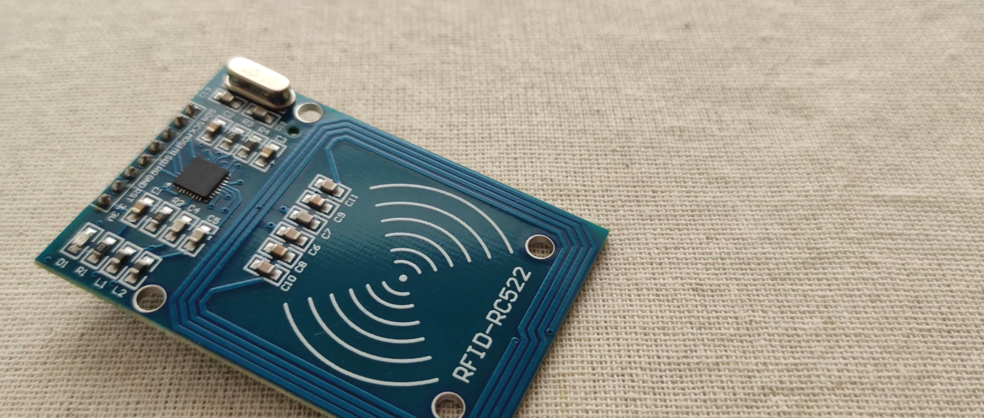
An RFID or radio frequency identification system consists of two main components, a tag attached to the object to be identified, and a reader that reads the tag.
A reader consists of a radio frequency module and an antenna that generates a high frequency electromagnetic field. Whereas the tag is usually a passive device (it does not have a battery). It consists of a microchip that stores and processes information, and an antenna for receiving and transmitting a signal.
Let’s take a look at the getID() custom function. First it checks whether there is a new tag placed near the reader and if so we will continue to the “for” loop which will get the UID of the tag. The tags that we are using have 4 byte UID number so that’s why we need to do 4 iterations with this loop, and using the concat() function we add the 4 bytes into a single String variable. We also set all characters of the string to upper cases and the end we stop the reading.
uint8_t getID() { // Getting ready for Reading PICCs if ( ! mfrc522.PICC_IsNewCardPresent()) { //If a new PICC placed to RFID reader continue return 0; } if ( ! mfrc522.PICC_ReadCardSerial()) { //Since a PICC placed get Serial and continue return 0; } tagID = ""; for ( uint8_t i = 0; i < 4; i++) { // The MIFARE PICCs that we use have 4 byte UID readCard[i] = mfrc522.uid.uidByte[i]; tagID.concat(String(mfrc522.uid.uidByte[i], HEX)); // Adds the 4 bytes in a single String variable } tagID.toUpperCase(); mfrc522.PICC_HaltA(); // Stop reading return 1;}
efore we enter the main loop, at the end of the setup section, we also call the printNormalModeMessage() custom function which prints the “Access Control” message on the display.
void printNormalModeMessage() { delay(1500); lcd.clear(); lcd.print("-Access Control-"); lcd.setCursor(0, 1); lcd.print(" Scan Your Tag!");}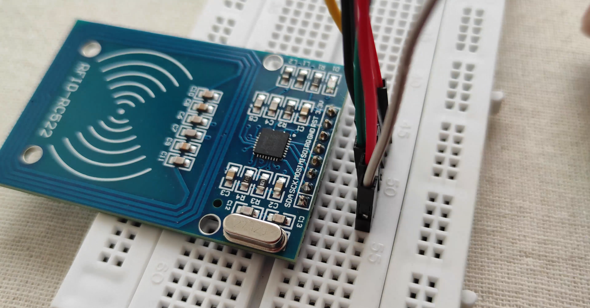
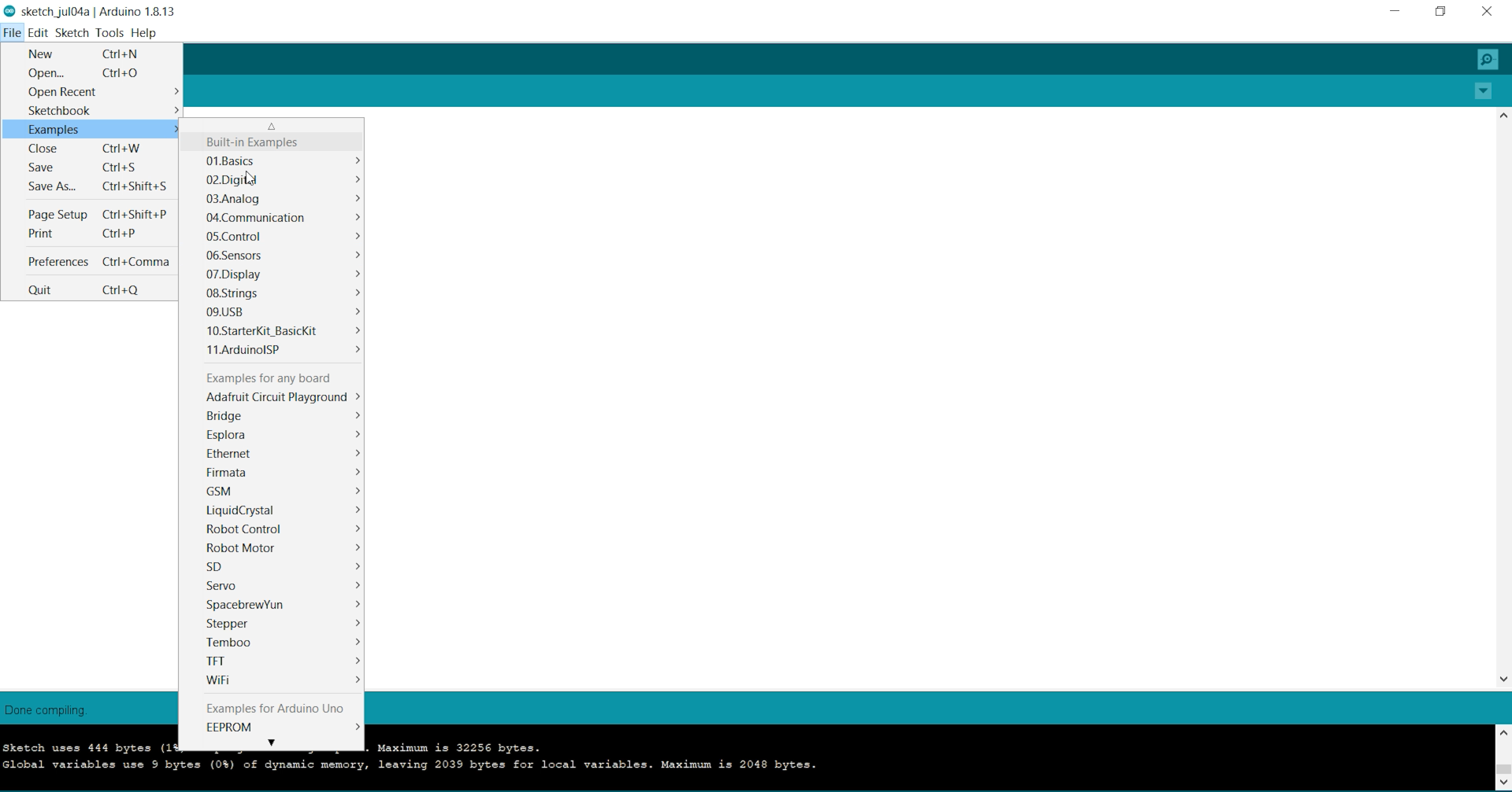
Now, before typing out the necessary code, you need to download the necessary library for this sensor from this repository.
Extract the contents from the zip folder "rfid-master" and add this library folder under the existing libraries of Arduino.
After doing so, restart your ArduinoIDE.
Now, our Arduino is ready to take commands and execute accordingly.
The Arduino Code has been uploaded at the end of this tutorial. Compile the code and eliminate "typo" errors (if any).
Now, its time to connect our Arduino with the RFID reader. Refer to the PIN wiring below,as well as the Connection schematic diagram for easy reference.
This is the information that you can read from the card, including the card UID that is highlighted in yellow. The information is stored in the memory that is divided into segments and blocks as you can see in the previous picture.
You have 1024 bytes of data storage divided into 16 sectors and each sector is protected by two different keys, A and B.
Write down your UID card because you’ll need it later.
Upload the Arduino code that has been suffixed here.
Demonstration
Approximate the card you’ve chosen to give access and you’ll see:
The RFID reader consist of a radio frequency module, a control unit and an antenna coil which generates high frequency electromagnetic field. On the other hand, the tag is usually a passive component, which consist of just an antenna and an electronic microchip, so when it gets near the electromagnetic field of the transceiver, due to induction, a voltage is generated in its antenna coil and this voltage serves as power for the microchip.
Now as the tag is powered it can extract the transmitted message from the reader, and for sending message back to the reader, it uses a technique called load manipulation. Switching on and off a load at the antenna of the tag will affect the power consumption of the reader’s antenna which can be measured as voltage drop. This changes in the voltage will be captured as ones and zeros and that’s the way the data is transferred from the tag to the reader.
There’s also another way of data transfer...
Read more »
 Sagar 001
 Laurent
 Marc-André Denis