ElectronicABC
GERBER:
https://mega.nz/file/2BZUzS5I#Ho_CL-OzVEn6gYVKNqsvBhpyxhEkakie7-dDosJz0Gs
SCHEMATIC DIAGRAM
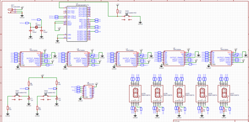
Here we will see the schematic diagram of how the connections will go to later create the tracks on the PCB, there we can see the values of each electronic component and also the integrated circuits.
FUNCTIONING
We will start with the most basic of the project, which is the power supply. This circuit has a 5V power supply. We will directly have to use a source of that voltage since it does not have a regulator included. If we connect a higher voltage source, it can burn the microcontroller, so we must be very careful.
Now we will see that our project works with the atmega328p, that is to say, with the arduino and we can program it with the ARDUINO IDE without problem, but we have to remove the PCB from the chip and record it in an ARDUINO. We have not included a direct programming to reduce the PCB a bit.
The programming is based on serial data, that is to say, with only 3 pins we can control the 74HC595 integrated circuits. We will use the common cathode displays for the visualization of the numbers and also 3 pushbuttons to control the timer, that is, 1 start, 1 stop and 1 reset this timer controls approximately 9 hours 59 minutes more than enough time for our projects
CODE ARDUINO
int clockpin = 8; //Cuando ay que leer los bit      SH
int data     = 6;   //Envio datos                     DS
int latch    = 7;  //indica pin de salida en el chip ST

// no cambiar el const int
const int  left_sen  = 2;    // pin 2 como entrada para el sensor izquierdo
const int  right_sen = 3;    // pin 3 como entrada para el sensor derecho

//VARIABLES PARA EL CONTADOR ASCENDIENTE
// estas variables si puede ser cambiado
int contador             = 0;
int contadorU            = 0;
int contadorD            = 0;
int contadorC            = 0;
int contadorM            = 0;
int contadorUU           = 0;
int estado_left_sen      = 0;      // estado  del pulsado actual
int lastButtonState_left = 0;     // estado  del pulsado anterior

boolean start            = false;
boolean stopp            = false;

//VARIABLES PARA EL CONTADOR DESCENDIENTE
// estas variables si puede ser cambiado

int estado_right_sen      = 0;         // estado  del pulsado actual
int lastButtonState_right = 0;     // estado  del pulsado anterior

const int alrm = 12; // alrm

//Aqui esta el array que contiene todos los UNDs para nuestro display
//El display tiene las conexiones alcontrario ell pin 8 del 74hc595 es el primer dijito binario

const int NUM[] = { // display B
  63,    //Numero 0 en binario es : 11111100
  6,     //Numero 1 en binario es : 00000110
  91,    //Numero 2 en binario es : 11011010
  79,    //Numero 3 en binario es : 11110010
  102,   //Numero 4 en binario es : 01100110
  109,   //Numero 5 en binario es : 10110110
  125,   //Numero 6 en binario es : 10111110
  7,     //Numero 7 en binario es : 11100000
  127,   //Numero 8 en binario es : 11111110
  103,   //Numero 9 en binario es : 11110110
  63,    //Numero 0 en binario es : 11111100
};

void setup() {

  pinMode(left_sen, INPUT);
  pinMode(right_sen, INPUT);

  pinMode(latch, OUTPUT);
  pinMode(clockpin, OUTPUT);
  pinMode(data, OUTPUT);

  pinMode (alrm, OUTPUT);

  digitalWrite(latch, LOW);
  shiftOut(data, clockpin, MSBFIRST, NUM[contador]); // lee el arreglo y pasa cada NUM a lectura binaria
  shiftOut(data, clockpin, MSBFIRST, NUM[contador]); // lee el arreglo y pasa cada NUM a lectura binaria
  shiftOut(data, clockpin, MSBFIRST, NUM[contador]); // lee el arreglo y pasa cada NUM a lectura binaria
  shiftOut(data, clockpin, MSBFIRST, NUM[contador]); // lee el arreglo y pasa cada NUM a lectura binaria
  shiftOut(data, clockpin, MSBFIRST, NUM[contador]); // lee el arreglo y pasa cada NUM a lectura binaria
  digitalWrite(latch, HIGH);
}
void loop()
{
  estado_left_sen = digitalRead(left_sen);
  estado_right_sen = digitalRead(right_sen);

  if (estado_left_sen != lastButtonState_left) {
    if (estado_left_sen == LOW) {
      start = true;
    }
  }
  lastButtonState_left  = estado_left_sen;

  if (start == true) {
    if (contadorU >= 10) {
      contadorU = 0;
    }
    if (contadorU >= 9) {
      contadorD++;
    }
    if (contadorD >= 6) {
      contadorD = 0;
      contadorC++;
    }
    if (contadorC >= 10) {
      contadorC = 0;
      contadorM++;
    }
    if (contadorM >= 6) {
      contadorM = 0;
      contadorUU++;
    }
    if (contadorUU >= 10) {
      contadorUU = 0;

    }
    contador++;
    contadorU++;
    cont ();
    delay(1000);
  }

  if (estado_right_sen != lastButtonState_right ) {
    if (estado_right_sen == LOW) {
     start =false;
    }
  }
  lastButtonState_right  = estado_right_sen;
}
void cont() {
  digitalWrite(latch, LOW);
  shiftOut(data, clockpin, MSBFIRST, NUM[contadorU]); // lee el arreglo y pasa cada NUM a lectura binaria
  shiftOut(data, clockpin, MSBFIRST, NUM[contadorD]); // lee el arreglo y pasa cada NUM a lectura binaria
  shiftOut(data, clockpin, MSBFIRST, NUM[contadorC]); // lee el arreglo y pasa cada NUM a lectura binaria
  shiftOut(data, clockpin, MSBFIRST, NUM[contadorM]); // lee el arreglo y pasa cada NUM a lectura binaria
  shiftOut(data, clockpin, MSBFIRST, NUM[contadorUU]); // lee el arreglo y pasa cada NUM a lectura binaria
  digitalWrite(latch, HIGH);
}
ELECTRONIC COMPONENTS
-1 DC JACK
-3 PUSHBUTTONS NOT 4 PINS
-1 ATMEGA328P-PU
-3 RESISTORS 10K 1206
-2 RESISTORS 100ohm 1206
-2 ELECTROLYTE CAPACITORS 1UF 25V
-5 RESISTORS OF 1K 1206
-1 CYSTAL OF 16MHZ
-4 COMMON CATHODE DISPLAYS
-1 INTEGRATED CIRCUIT 74HC14
-5 INTEGRATED CIRCUITS 74HC595N
-1PCB
FEATURES
-VIN 5VDC
-CHRONOMETER UP TO 9 HOURS 59 SECONDS
-PROGRAMMING THROUGH SERIAL DATA
-START BUTTON
-STOP BUTTON
-RESET BUTTON
EASYEDA
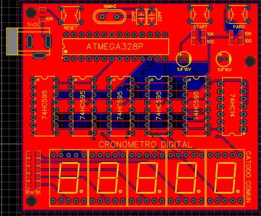
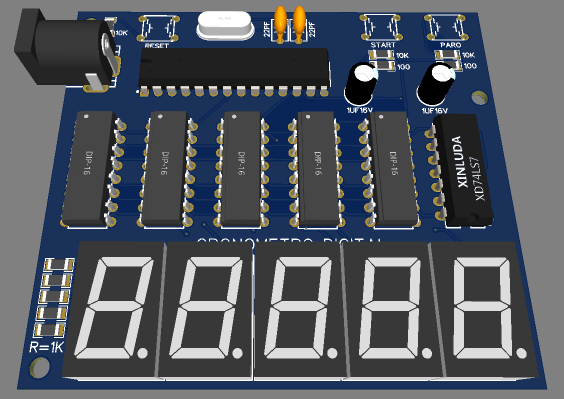
Here we will see the design of the pcb, the tracks and the 3D image made in the EASYEDA electronic design software
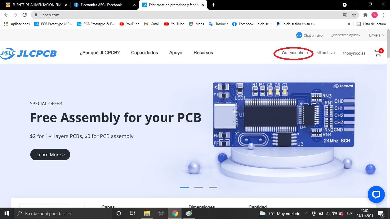
JLCPCB
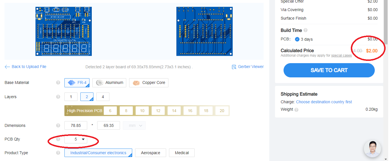
Once the pcb is designed, we will send our friends from JLCPCB to manufacture our PCB.
5pcbs only $2
JLCPCB number 1 PCB manufacturing company worldwide professional pcbs and excellent finish.
GERBER PCB:
https://mega.nz/file/2BZUzS5I#Ho_CL-OzVEn6gYVKNqsvBhpyxhEkakie7-dDosJz0Gs