Sagar 001
There are two type of digital circuits, some need a clock pulse trigger known as synchronous and other are asynchronous (no need of trigger). Asynchronous action is fast but unpredictable that’s why whole the microcontroller world run at a desirable clock. Nowadays CPU working frequency is very high (current Gen Intel i9 13 gen can be boost up to 6GHz). But basics will always remain the same. I want to make a clock signal generate using very few components. Which is not only able to produce clock signal but we can also control the duty cycle and frequency. Using this we can test a lot of basic sequential circuits and hence we are able to find the working principle of these circuits Like flip flops and counters.

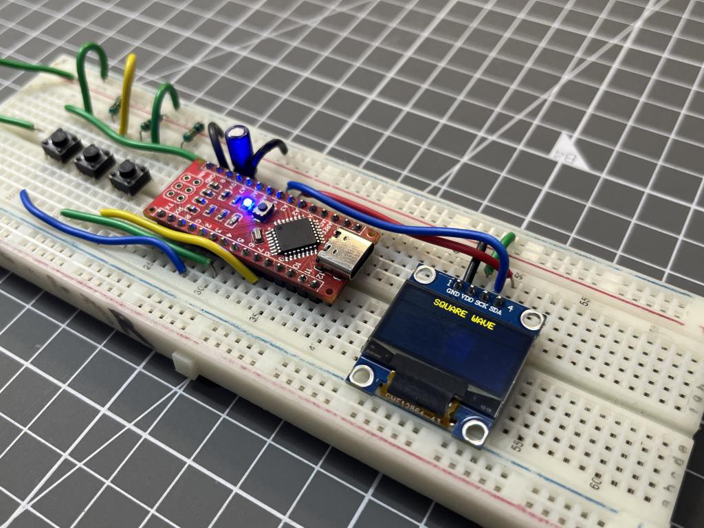
We can do the job using a very famous 555 IC but the problem is we want a feedback, I do not want to calculate the resistor and capacitors again and again for variable system. so that’s why I am using Arduino uno, and a small OLED display shows the frequency and duty cycle which can be variable using some push buttons. Arduino has 3 timers and using these we can produce a clock pulse by dividing the Arduino’s 16Mhz crystal frequency into parts. A beautiful pulse of 1MHz can easily be produced using this.
I am using EasyEDA for circuit designing and then order the PCB from JLCPCB. Christmas and new year offer is waiting for you order any 2-8layer PCB just in $2 (for limited period of time). Sign-up to JLCPCB using this link and get new user coupons of worth $54.
Components Required:
1) Arduino UNO
2) OLED or 16x2 LCD (with I2C)
3) 10K resistor
4) 220uf capacitor
5) Tactile switches
6) Custom PCB from JLCPCB
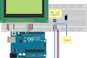
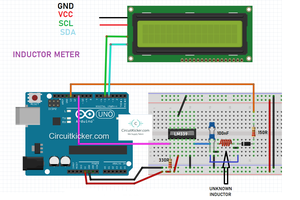
Circuit diagram:
You can find two different codes below, one for the OLED display and other one for the 16x2. The circuit diagram and connection details of both circuits are shared below. Both the screens work on a I2C address which is controlled by Arduino and a 4-wire interface is set between Arduino and screen. So the circuit remains the same just change the screen and code respected to it.
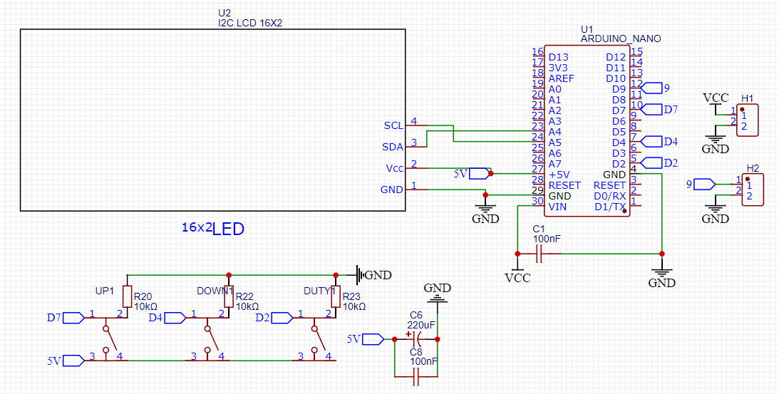
Arduino – Screen interface
A4 - SDA
A5 – SCL
5V – VCC
GND - GND
The push buttons are used to change the frequency Up-down and the duty cycle of the square wave. These resistors are pulled down using 10k resistor and activated when got 5v signal.
D7 – frequency up
D4 – frequency down
D2 – duty cycle
A 220uf capacitor is required between the power pins to reduce the power supply irregularities. Digital pin 9 is used for PWM square wave output.
Gerber files:
I designed the Gerber files for 16x2 LCD because it is widely available and has a pretty good viewing angles. Just plug the Arduino and Screen in the PCB shield after soldering the SMD resistors and tactile buttons.

You can download the Gerber files from here. Upload the Gerber files on JLCPCB and get your 5 piece of 2–8-layer PCB in just $2. JLCPCB is the leading PCB manufacturer from China and dealing in PCB prototyping, SMT assembly, Stencil making, 3D printing, Full PCBA and high precision PCB making.
Code for Arduino:
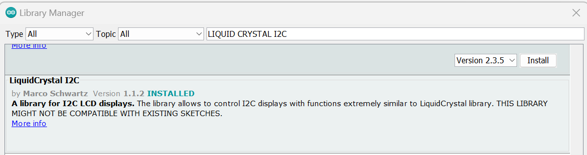
This code works with 16x2 LCD and Arduino UNO. You can download the required libraries directly from Arduino IDE library manager section under tools menu. Code for OLED display is given below or you can download all the required materials from here.
#include <TimerOne.h>
#include <Wire.h>
#include <LiquidCrystal_I2C.h>
LiquidCrystal_I2C lcd(0x27,16,2);  // set the LCD address to 0x27 for a 16 chars and 2 line display
unsigned long t=1000,f,k=512;// default 1000 μs (1000 Hz), meander, pulse
byte k1,kn,kn1,kn2;
int drive,drive0;
void setup()
{
lcd.init();                      // initialize the lcd
lcd.init();
lcd.backlight();
pinMode(9, OUTPUT);
pinMode(7,INPUT);
pinMode(4,INPUT);
pinMode(2,INPUT);
}
void loop()
{
Timer1.initialize(t); // period
Timer1.pwm(9, k); // k - fill factor 0-1023.
kn=digitalRead(7);
kn1=digitalRead(4);
kn2=digitalRead(2);
if(kn==HIGH){ // decreasing the period
drive++;
if(drive<30){
t=t-1;
}
// if the button is held...
Read more »
 biemster