Mike Tripoli
I needed a test bed for testing ultrasonic and LIDAR transducers. I could have bolted them to the bench, set up a scale and moved a piece of foam core back and forth to check the distance, but that wouldn't be any fun. So, I decided to build a little robot instead and put the transducers on it. I still did my distance testing; after that the robot was let go and it just tools around, avoiding bumping into objects.
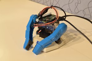
The base is a chassis I took from a Raspberry Pi kit, I wasn't interested (this time) in building everything, build or buy didn't matter in this case. I planned on using an Arduino UNO R3 for the brains, an Arduino Motor shield R3, and a breadboard to top it all off. This board holds the three 2N7000 MOSFET's as well as a DC-DC SMPS (Switch Mode Power Supply) from DROK. The robot runs on a custom made LI-Ion battery, 8.4V@2400mAh; the steering servo runs at 5V. The SMPS has multiple voltage taps; I set it for 5V. The power pin for the servo runs from the SMPS.
Every robot should have "light up eye's and this one is no exception. I used 10mm diffused RGB common anode LED's. A ballast resister was soldered directly to the LED, the power wire going to the 8.4V directly; the "open drain" FET drives the LED's , the gate being driven from the UNO directly.
The ultrasonic transducer is mounted right below the eyes, tilted slightly up. The "head" is actually a lawn ornament that had high power white LED's in the "eye sockets". I stole one from the front yard and stripped it of it's electronics *which used an 18650 Li-Ion battery, with a battery protector in place, along with the high power white LED's. I'm sure I'll find something to use this on in the future... The LED's were carefully hot-glued into place, wired together and connected to the 2N7000's. There is actually a routine in the code to drive the LED's any color in the spectrum, I have routines for green, red, magenta, blue, yellow, white and few more.
The transducers are directly wired to the UNO. The ultrasonic transducer uses two wires to the UNO, the LIDAR runs I2C and was connected that way.
The head has a large solar cell on the top of the head; under bright light it outputs 4V. At some point I'll connect that to the UNO and make it "light tracking" so that it drives around looking for the brightest spot and stopping there. As the light changes throughout the day the robot will "chase the light". I also intend to put a LIDAR sensor on the back so that it doesn't back into objects when turning and backing up.
The algorithm for collision avoidance is simple; when it detects and object, it runs a random routine on whether to turn left or right. It monitors the sensor until it no longer sees the obstacle, then goes straight. During normal running the eyes are green , when it detects an obstacle, the eyes flash red.
More of my projects can be seen at : https://scarydesign.wixsite.com/scary
 robotmaker team
 Elena Jasso
 Ahmed Azouz