 George Gardner
So, the project has gone under many changes, the largest of which is the layout of parts on the chassis. Turns out when I was modeling the base, I entered the diameter instead of the radius, causing me to believe that I had twice as much room (4x the area). In essence, I had much less space and had to re-think and re-orient all the parts.
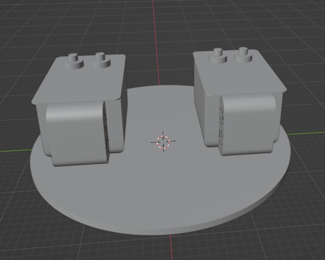
The new plan is to keep the transformers in a straight line, and rotate the motor upwards, mounting it in the vertical position between the two transformers. The middle part of the chassis is now planned to be used as a result. Previously, I decided I would double up on the bottom layer, but that is no longer an option.
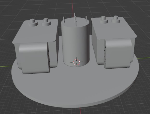
The power factor correction capacitor will go on the power input side of the transformers, still with a custom conduit cap leading from one of the knockouts on the transformer input. In addition, I've modeled a custom conduit to lead from the motor, where the wires protrude, back to the boxes as well.
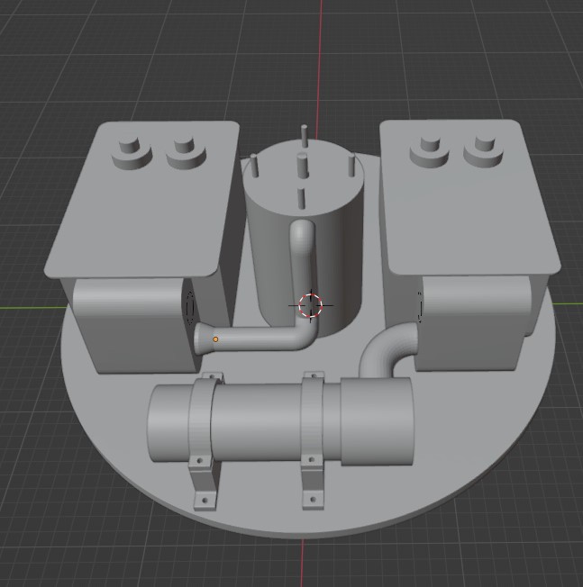
The PFC cap will mount to the base with custom printed brackets. There are (2) unused knockouts on the insides of the transformers that I will use to run the power from box to box. This will be standard EMT conduit with couplings. While the (2) boxes may get grounded together, I'll be running an additional grounding wire that is bolted to the chassis of each transformer to ensure they have a good ground connection.
I've read the case where the transformers should be connected to RF Ground, and others who say it should be connected to mains ground. After much reading, I've decided to go with grounding the transformers to mains ground and making use of an EMI filter. In a parallel combination, which is what I'm doing with (2) transformers, the cases should definitely be grounded to each other. Before running the parallel wires between each transformer, it's important to check phasing to make sure they're in phase with each other. There's a good video by Chris Boden of the Geek Group on phasing if you want to check that out below.
Basically, it entails bringing one of the hot HV leads from one transformer over to the other while they are both in operation. If an arc jumps across, they're out of phase, and these (2) leads should not be connected in the final build. Bear in mind that if you reverse any of the wires on the low voltage (mains) side, this phasing will change. Once I determined phasing, I put green electrical tape on each of the mains wires so I didn't hook them up backwards on the final build.
My transformers were identical - same make, model, size, etc,.. and oddly enough, the wires coming out of the primary side (there's a top and bottom wire) were not phased with each other, meaning I had to connect the upper wire on one transformer to the lower wire on the other to ensure the secondary side leads were phased with each other. So don't ever assume the internal wiring is the same - even if you have two identical transformers!
I purchased 12 gauge, 4 conductor wire as input to the transformers. The thinking there is (1) neutral, (1) hot for transformers, (1) hot for asynchronous motor, and (1) ground. I wanted independent control of both the transformers and the motor to ensure the motor is fully spun up before activating the high voltage transformers.
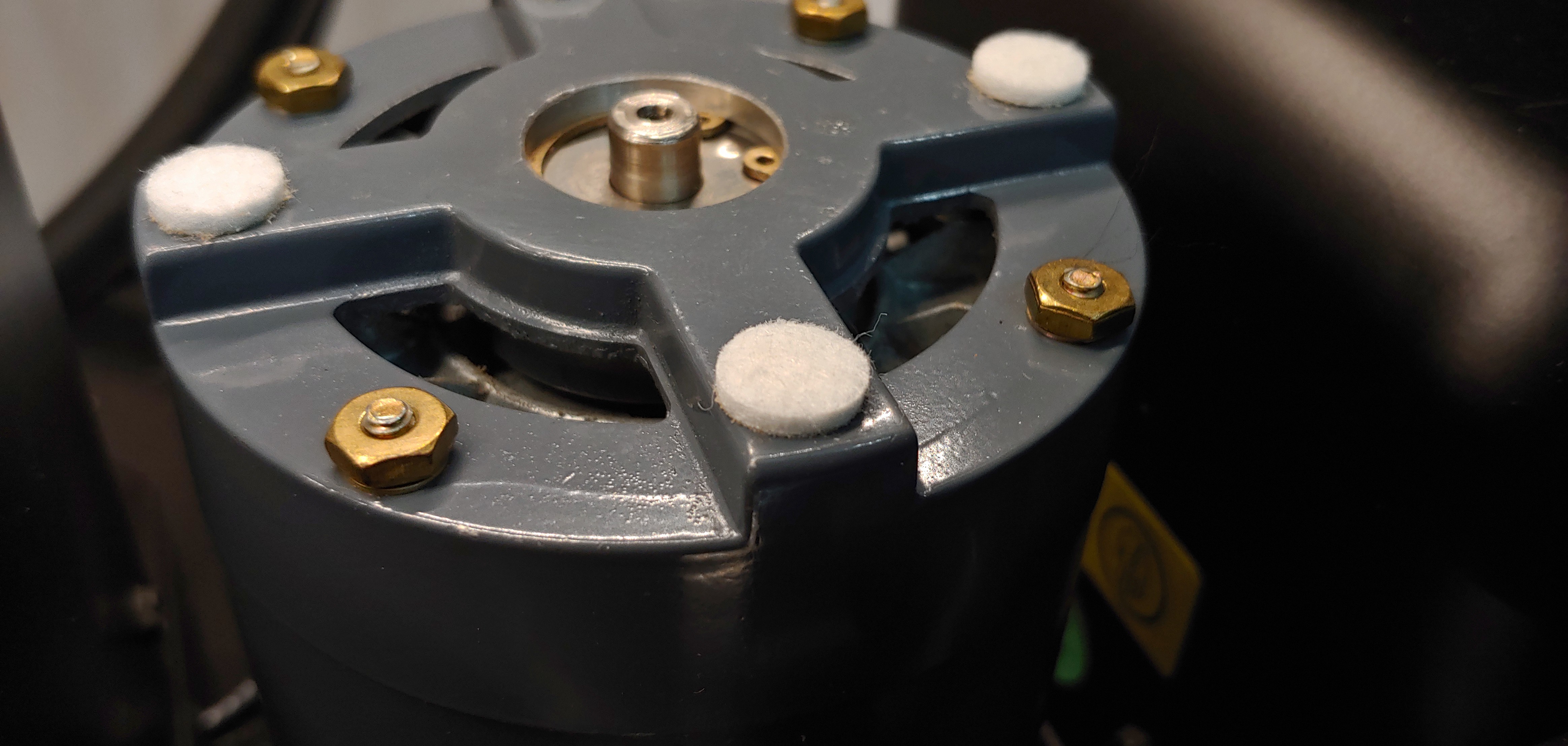
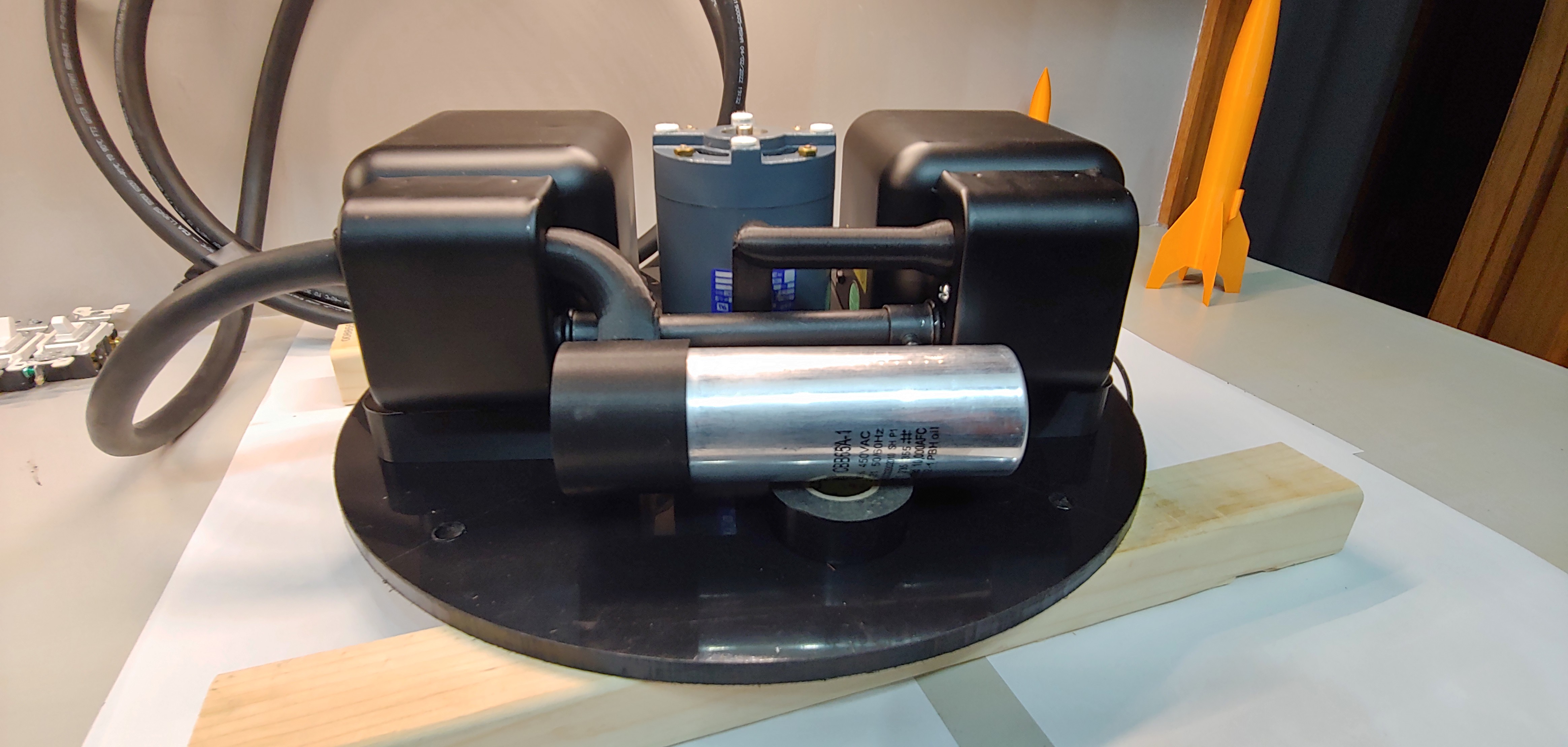
As seen below (on right transformer), the 4uF start/run cap for the asynchronous motor conveniently fit inside one of the transformer's electrical housings.
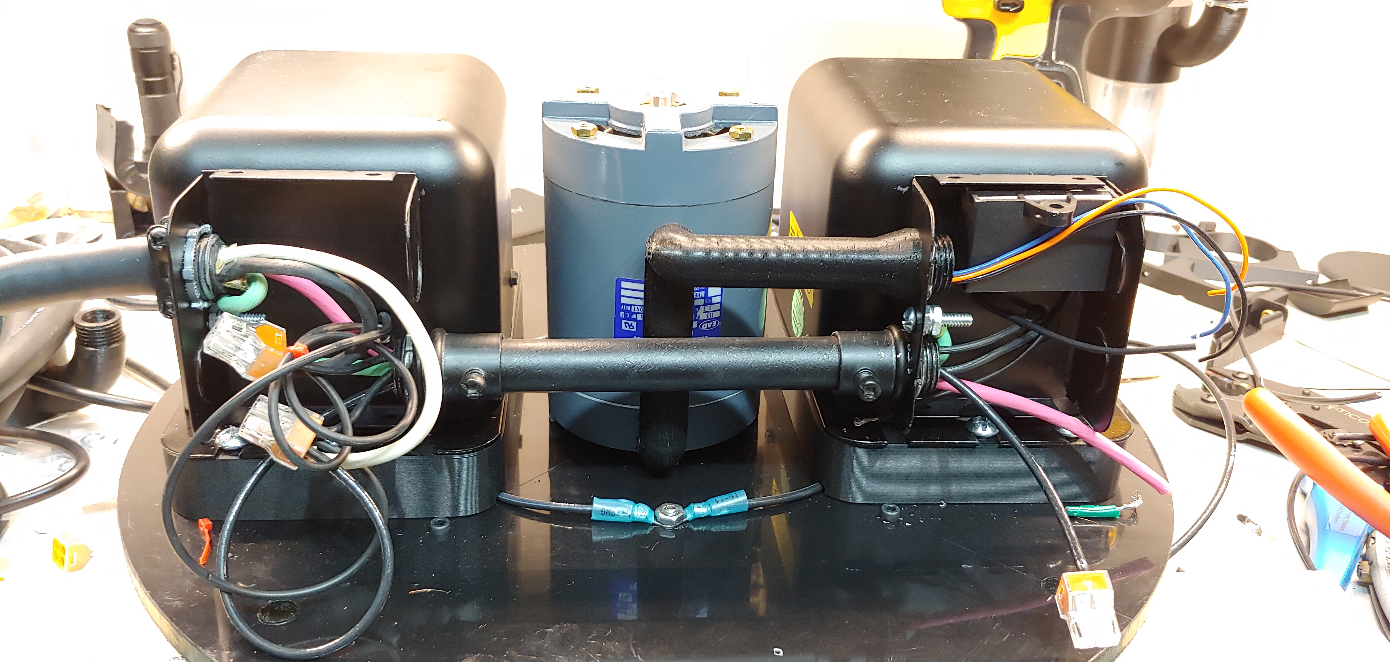
You can also see on the left side of each case, the grounding wire bolted to each case. Also notice the transformer mounting spacer used, which puts the total depth of the transformer w/ mount about 3 millimeters deeper than the motor. The idea here was to use 3mm felt pads (seen below) so the motor is not sitting directly on the base causing unnecessary noise -- like it won't be loud enough to begin with.
In the above image, the top is facing down, so the HPDE seen below the motor and transformer is the middle part of the chassis. You can see the bolt between the two transformers, which is the parallel connection between the two. Yes, I used standard 12 ga. wire for this due to the sheer cost of GTO wire. As a result, and in any application (even with GTO wire) I have to be mindful of the separation between the wires carrying the HV and the grounded case, which carry a 5kv potential between the two. Let's hope that doesn't prove to be a bad design choice.
It is for this reason I modeled the transformer mounts to have a channel to hold the HV carrying wires away from the the chassis. In theory, this looks nice, but it proved to be rather difficult to mount the transformers while keep the wire neatly tucked in the channel.
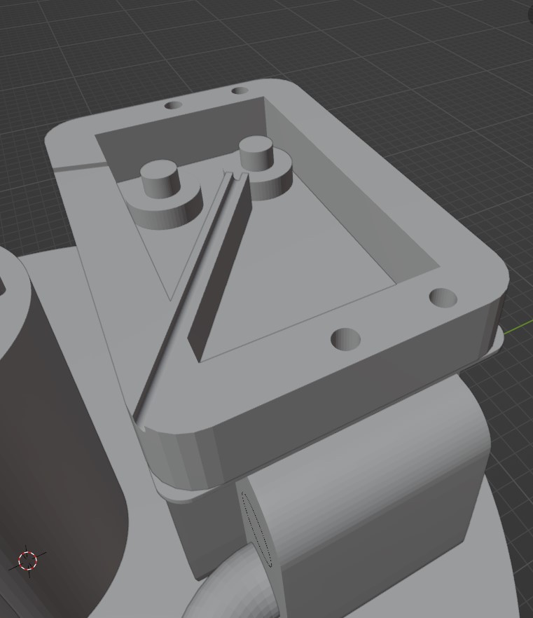
I only used (4) of the (6) transformer mounting holes, as using the innermost mounting holes would have put the metal fasteners uncomfortably close to the wires carrying the HV. In the end, the 1st level of the Tesla Coil turned out pretty nice, visually -- and I'm certainly hoping the performance of it will meet that same level.
Discussions
Become a Hackaday.io Member
Create an account to leave a comment. Already have an account? Log In.