1 Introduction
Efficient communication systems are necessary in the modern world in every industry. This includes conventional business, personal ventures, and national defense. These communication systems can be grouped into two categories - centralized and decentralized.
For the purpose of the project, centralized communication is defined as a network that relies on some entity providing connectivity services between separate endpoints. Some of these include email, text, and private chat applications since they rely ultimately on the services of Internet Service Providers and Cellular Service Providers for the propagation of data.
Decentralized communication systems include those that are mostly operable without relying on a separate service. This includes systems such as HAM radio. Using decentralized communication, users are able to network directly with each other without needing to pay for a service other than power.
The goal of this project is to combine the benefits of both centralized and decentralized methods to provide reliable digital communication between users without the need for the internet. In addition, this network makes it difficult to track the correspondence between users since these nodes can be used mobily and use pseudo randomly generated identifiers. This network will excel in situations where two parties need to communicate securely and anonymously. This may include civil defense, clandestine operations, and personal communication.
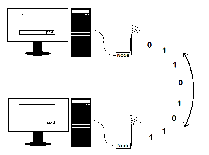
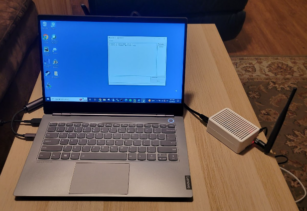
To communicate using this network, a small device, called a node, is attached to and controlled using a computer as in Figure 1. The node can be attached to the computer either directly using an Ethernet cable or both can be on the same local network, although internet access is not used and is thus not required. Each node consists of a microcomputer and a radio transceiver. The user interacts using the graphical user interface (GUI) installed on the host computer which allows them to add recipients via public and shared keys, export public and shared keys, and send and receive messages.
2 Hardware
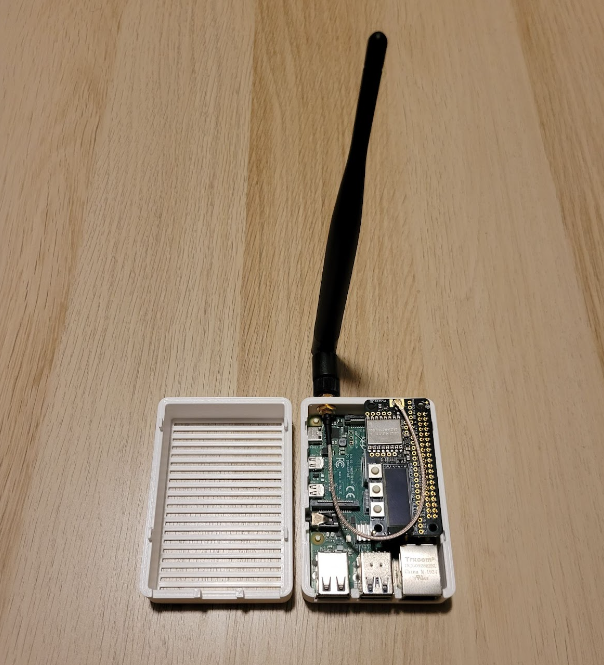
A Raspberry Pi 4 was used as the microcomputer of choice to drive this build. This was done for a multitude of reasons including reliability and familiarity of programming in Python, but also due to the flexibility with memory management. The Raspberry Pi 4 has 4GB of RAM which is more than sufficient to accommodate the potentially large amounts of data associated with the features of this network. Fragmentation and acknowledgements in particular require potentially large amounts of memory to store the various data mappings.
The Adafruit LoRa Radio Bonnet (915MHz) was used as the radio transceiver. This was done partly to take advantage of the license-free Industrial, Scientific, and Medical (ISM) frequency bands but also due to the low power requirements and long ranges. Using 5dbi omnidirectional antennas, the receivers can communicate to at least 2km when they are in line of sight. Using different antennas will produce varying results.
Due to the ‘plug-and-play’ nature of these components, no additional PCB design was necessary which left the primary development hurdle to be the software. Appendix B includes some images to help better illustrate this component. The pinout connections can be found on Adafruit’s website.
The enclosure was designed using Fusion 360 and printed using an Ender 3 Pro 3D printer. PLA filament was used due to the affordability and ease of use. Table 1 details the print settings used for this build. The enclosure is mostly a standard Raspberry Pi case with the exception of the increased height to accommodate the radio transceiver and a hole to mount the antenna. In addition, cooling holes were added onto the case to help reduce ambient temperature.
Layer Height | 0.16mm |
Infill Density | 20>#/p### |
Infill Pattern | Cubic |
Print Temperature | 200℃ |
Build Plate Temperature | 60℃ |
Print Speed | 40.0mm/s |
Print Time | 11 hours 9 minutes |
3 Routing
The network topology for this communication system is a mesh network. This is inherent in that each node has an arbitrary location and communicates by broadcasting to all nodes that can receive the signal. Since this is the case, managing the data actively being transmitted is very important in the overall efficiency of the system.
The primary hindrance of this type of network is that each radio transceiver can either send or receive, but not at the same time. This poses a problem when a node is trying to send a message, but another nearby node has already begun transmitting and thus the original node begins to receive.
These collisions can be relieved by using features that help with semi-guaranteed delivery as discussed in Section 4, Fragmentation. Another way of attempting to mitigate collision and interference can be solved by using efficient routing techniques. By controlling which messages a node forwards, it can alleviate some of the congestion in an area since less overall messages may be sent.
The particular routing technique used in this network is controlled flooding. With a standard flooding technique, a node will resend each message it receives unless the node itself is the final destination. This poses a problem in a large network where messages may propagate to the edge of the network and then reflect and move in the other direction. This may cause messages to be continuously transmitted despite potentially having reached the destination already. Notice in Figure 2 how the arrows are bidirectional between nodes when using flooding since a message will propagate backwards towards the original sender. This means the final recipient may receive a message continuously.

A controlled flood is similar to the standard flood, however, a node will not resend a message that it has already sent within a specified threshold time. This helps control the possible endless propagation of some messages. Figure 3 demonstrates the operation of a controlled flood as opposed to a traditional flood. The arrows point in a single direction since a node whose already received a specific message will discard it upon reception a second time. This will help deter backward propagation. In a smaller network such as this that in Figure 3 with only five nodes, messages will stop propagating rather quickly, however, in larger networks backward propagation may still occur if the threshold time is met by the time a message gets back to a node who has already sent it.
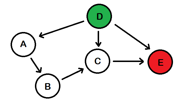 Figure 3: Demonstration of routing using controlled flooding with the sender in green and the intended recipient in red.
More advanced routing techniques will allow a message to intelligently propagate through a network without each node having to forward the message. Dijkstra's Algorithm (DA) is one such example. DA finds the shortest path between two nodes. This means that before a node sends a message, it will calculate the next hop, or temporary recipient, using DA. Only when the specified temporary recipient receives the message will they find the next temporary recipient and rebroadcast the message. This process will continue until the message gets to the final recipient [1]. Although DA and similar algorithms will, in theory, improve the efficiency of the network since a message will have a defined route, there is additional overhead needed. Nodes need a way to ‘discover’ other nodes which means they will periodically need to broadcast a discovery probe. In addition, the calculations for finding the optimal path will take time and slow down propagation time. The node designated as the next temporary recipient will also need to be specified in the message packet which means there will be less space allocated for transmitting actual data. Finally, there would need to be contingencies in place if a temporary recipient is determined who is unable to receive messages.
The issues discussed with pathfinding algorithms may not congest the network enough to justifiably say that a controlled flood is best, but it would take longer and require more hardware to determine if there would be a significant benefit over controlled flooding. Since only two nodes are currently being used to test the network, controlled flooding is sufficient, but will need to be reevaluated in order to determine scalability concerns.
4 Fragmentation
The buffer size of the rfm9x LoRa module is 256 bytes [2]. This means that when considering header information such as destination, control flags, and timing information, there likely wouldn’t be enough space to include a lengthy message. This is even more of an issue when using encryption since the data being sent will be greater in size than the original data.
A typical header for this communication network was designed to be approximately 80 bytes, which leaves about 176 bytes for the message. This message is post-encryption, which means the actual size of the data is much larger than what the user is actually trying to send. If the size of the complete message is larger than 176 bytes, then it must be broken into pieces and sent separately. Logistically, this means each packet also needs to contain a tag that indicates the order of fragments so that the receiving node can combine all individual fragments back into a complete message and then forward it to the user.
Upon receiving a message that has arrived at its destination, each node will check to see if it is a fragment. If that message is not a fragment, it will be pushed onward with no further interaction from the fragmentation system. If the message is only a piece of a complete message it is stored into memory. After receiving a fragment, the node will check to see if it has all fragments to that message. Once all fragments are received, each individual data segment is extracted and put back together in order. The assembled message is then forwarded. This entire process is summarized in Figure 4.

The advantage of using fragments is that longer messages can be sent automatically, which is necessary since messages for this node include encryption and a header that will typically be much longer than the 256 byte limit.
5 Acknowledgements
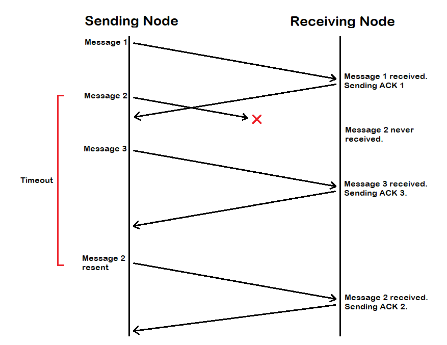
A large concern of wireless communication, as mentioned in section 3, is collisions due to radio transiever’s half duplex behavior. In order to improve the reliability and scalability of this network, an acknowledgement system was integrated in order to provide guaranteed delivery of messages. The system for this project was modeled after that of the Transmission Control Protocol (TCP). TCP’s implementation enables a message to be resent if the recipient has not responded that it has received the message [3].
In order for this to work, both the sending and receiving nodes have to work together. Upon receiving a message, a node will respond to the sender with an acknowledgement which does just that - acknowledge that the message was received. A node will continue to periodically send a message until it has received an acknowledgement or it has tried long enough to consider a recipient node stale - that is it no longer has the ability to receive a message either because it lost power or interference or a break in the network chain prevented messages from propagating correctly. The logic for acknowledgments is shown in Figure 5.
Timing for this system can be difficult to optimize. A node should wait longer than twice the time it takes for a message to propagate all the way from a sender to its final destination. But since this network assumes an arbitrary number of intermediate nodes, setting a static wait time will not be the most efficient means. Although this is the case, this is the current implementation due to difficulty with testing using such few nodes. As more nodes are integrated into the network, this system will be more dynamic and update as a node receives and sends more messages.
6 Encryption
Encryption is one of the most integral parts of this network. Without it, any messages a user wishes to send would be viewable by anybody with the ability to monitor radio frequencies and the time to decode the message. Although encryption allows for the secure communication between two parties, it comes at a cost.
Encryption is, generally speaking, computationally expensive. This primarily comes from the actual encryption and decryption algorithms. Since messages sent using this network protocol are end-to-end encrypted, encryption and decryption will each only be performed once per sent message. This means that the time it takes to encrypt and decrypt will be somewhat negligible compared to the propagation time of a message to get from the original sender to the final destination.
Another consideration is the length of the ciphertext. Ciphertext is the encrypted data, which, for any reputable algorithm, will likely be longer than the plaintext. This means that more fragments will need to be sent on the network in order to deliver the entire message which may cause slower propagation times due to congestion.
The final issue with encryption is key management. This concerns how users and nodes will distribute keys in order to encrypt messages meant for another node. This will be discussed in Section 8, Key Management. The important thing to note here is that depending on the implementation, this may require additional control messages in order to distribute keys thereby increasing congestion.
The RSA algorithm was chosen for encryption on this network. RSA is a public key encryption algorithm which means that a different key is used to encrypt and decrypt. The intended recipient's public key, known to everybody, is used to encrypt the message, and the recipient's private key, known only to the recipient node itself, is used to decrypt. These keys are based on prime factorization [4]. The basis of this is that given two large prime numbers it is trivial to calculate the product, but given the product of two large prime numbers, it is infeasible to find the factors. Figure 6 demonstrates the high level operation of using RSA encryption (and public key encryption as a whole).

RSA was chosen due to several factors. The first is that RSA is reasonably secure, especially using appropriate key lengths (This network uses keys 256 bytes long). The next reason is that key distribution is logistically easier with public key cryptography since a node needs to only request a public key before receiving the key, meaning no key exchange will need to take place as with something similar to the Diffie-Hellman Key Exchange Protocol.
7 Message Authentication
Message authentication is a feature that allows a user to verify that a message is coming from the expected sender. This feature requires a unique key to be shared between two nodes. Although message authentication is not required, it can significantly improve trust between two interacting users.
In order to authenticate messages, this network uses message authentication codes (MAC) generated by using a hashing algorithm (HMAC). As with any secure hash function, it needs to have the ability to be applied to any size data, produce a fixed length output, be practical to compute, be one-way such that it is very difficult to reverse given only the hash, and collision resistant so two inputs will not map to the same output [5]. SHA256 was chosen since it meets these requirements. The SHA256 hashing function produces a hash 256 bits in length, which equates to 2256 possible outputs. Using SHA256 on two similar inputs will also produce significantly different results. These properties, among others, motivated its use.
Every sent message includes an attached HMAC. To generate this code, the concatenation of the unencrypted message and shared key is hashed. This hash (HMAC) is attached to the message, encrypted, then sent. Once a user receives a message, they unencrypt the message and check to see if the HMAC is valid. To do this, the user hashes the message combined with their copy of the shared key and checks to see if the hash is identical to the received HMAC. If they are the same, then the message is deemed authentic, and if it is not, the message is deemed unauthentic [6]. This entire process is summarized in Figure 7. Listing 2 in Appendix A also includes a demonstration of this functionality.

If two nodes do not share a key, a random HMAC is generated and sent with the message. This means that a received message deemed ‘not authentic’ does not necessarily mean that it was not sent from the expected sender. It may mean that the nodes do not share a key at this time. The choice to include a random HMAC was done in order to protect nodes from attackers who may be able to see which nodes are engaging in unauthenticated communication. In an attempt to mitigate this problem, an HMAC is included with every message, be it random or not.
8 Key Management
Key management is one of the more difficult tasks when dealing with cryptographic systems. Ordinarily, keys will be distributed automatically by applications or computing systems when needing to communicate with each other, however, this network has limitations concerning congestion and collisions. In an attempt to limit the number of miscellaneous control messages sent between nodes, manual key distribution was chosen. This means that the user will have to physically give another user either their public key for message encryption or the shared key for message authentication. This can be done in a number of ways including email (preferably encrypted) or using a USB storage device.
Although manual key distribution is very inefficient, it has the ability to improve security since a random node no longer has the ability to request a public key from the node. This means that only authorized nodes who have been given the public key can send it to a certain recipient. This may pose a problem if the shared key is intercepted because an attacker could maliciously pose as an authenticated contact of a node. This would require, however, that an attacker have both the shared and public key.
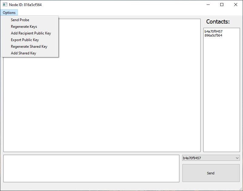
In order to make key distribution as streamlined as possible for users, the application includes options to regenerate public-private key pairs, generate a shared key, and export and import both public and shared keys. This means that if a user ever expects malicious activity, they can regenerate and redistribute their keys. The options for this functionality can be seen in a screenshot of the software in Listing 1 of Appendix A.
9 Conclusions
This network offers a solution for decentralized and secure communication using radio transceivers. Sections 2 through 8 explored some of the design details and considerations for various features of this specific project. Additionally, some of the drawbacks of certain design choices and possible solutions for these drawbacks were discussed in these sections.
Security is perhaps the most important piece of any reliable communication system, and as such should be periodically reevaluated for robustness. Future upgrades may include different or additional encryption standards and message authentication techniques. In order to improve the efficiency and scalability of routing, a further study will need to be done in order to determine the benefits and drawbacks of using different routing algorithms and how they will affect the scalability of the network. In addition, the application may include features for automatic key distribution that would still circumvent congestion in the network. Since network congestion and collisions are two of the biggest inhibitors for scalability, techniques for increasing network features while limiting these behaviors will need to be examined.
The features of this network were successfully implemented. The logistically focused features include routing, fragmentation, and acknowledgements. These were tested both with and without encryption and using a combination of short and long messages in order to verify functionality. Security focused features including encryption, message authentication, and key management were implemented once the logics were already working. These features were tested by sending messages between the two nodes under different circumstances. This includes things such as intentionally failing to distribute the correct keys (both public and shared) and analyzing the behavior of regenerating and adding keys mid-exchange. The basic operation of both the logistics and security focused features were verified through this process.
Although the testing used for this network was successful and provided an introductory proof-of-concept for a radio based communication in this manner, this will need to be expanded upon in order to produce more genuine results by using more nodes. Future additions to this project will certainly include some of the aforementioned features which may improve the operation and ease-of-use of this network.
10 References
[1] J. Kurose, K. Ross, “The Network Layer: Control Plane” in Computer Networking - A Top-Down Approach. Pearson Education Inc., Seventh Edition., Hoboken, New Jersey, US, 2017. ch. 5, sec. 5.2, pp. 379-383.
[2] Low Power Long Range Transceiver Module Model No.:RFM95W/96W/98W, Version 2.0, Hope Microelectronics Co., China, pp. 1, 30.
[3] J. Kurose, K. Ross, “Chapter 3: Transport Layer” in Computer Networking - A Top-Down Approach. Pearson Education Inc., Seventh Edition., Hoboken, New Jersey, US, 2017. ch. 3, sec. 3.5, pp. 379-383.
[4] “RSA Encryption.” Wolfram MathWorld. https://mathworld.wolfram.com/RSAEncryption. html (accessed Oct. 30, 2021)
[5] W. Stallings, L. Brown, “Cryptographic Tools” in Computer Security: Principles and Practice. Pearson Education Inc. Ed. 4, cp. 2, sec. 2.2.
[6] HMAC: Keyed-Hashing for Message Authentication, RFC: 2104, Network Working Group. [online]. Available: https://www.ietf.org/rfc/rfc2104.txt
Appendix A - Software
Listing 1: Screenshot of the GUI for node 816a5cf564. The ‘Options’ tab allows a user to manage the keys. The ‘Contacts’ list shows all nodes whose public keys are available on node 816a5cf564. The dropdown option allows the user to select the recipient of the message.
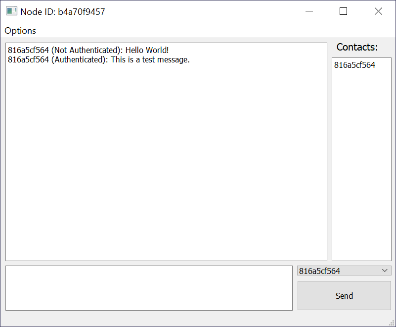
Listing 2: Screenshot of the GUI for node b4a70f9457 that displays two messages received from node 816a5cf564. The first message is considered ‘Not Authenticated’ because no shared key was distributed between these nodes prior to sending. The second message is deemed ‘Authenticated’ since a shared key was added between the nodes and the received message was verified authentic.
Appendix B - Hardware
Listing 1: Picture taken of a node connected to a laptop through an Ethernet cable.
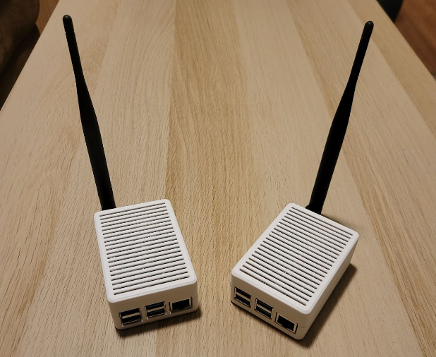
Listing 2: Picture of two nodes sitting side-by-side.
Listing 3: Picture of one of the nodes opened to showcase the internals.