 Saabman
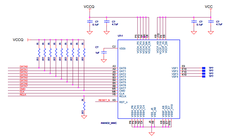
Ive been working through the Data sheet to make sure Ive git all the connections I need. The data and clock lines seem somewhat straight forward but the power rails are a little more complex.
According to the data sheet VCCQ is 1.8V and VCC is 3.3V the data sheet even provides a Reference schematic which I think will be safestto follow - though I will not be making a PCB for this but just dead bugging it. The plan is to solder the decoupling caps straight to the balls on the chip. She aint going to be pretty but as long as it works :-)
Discussions
Become a Hackaday.io Member
Create an account to leave a comment. Already have an account? Log In.