 Ruslan
In the diagram, you can see the pinout of the intermodule connectors in next.module
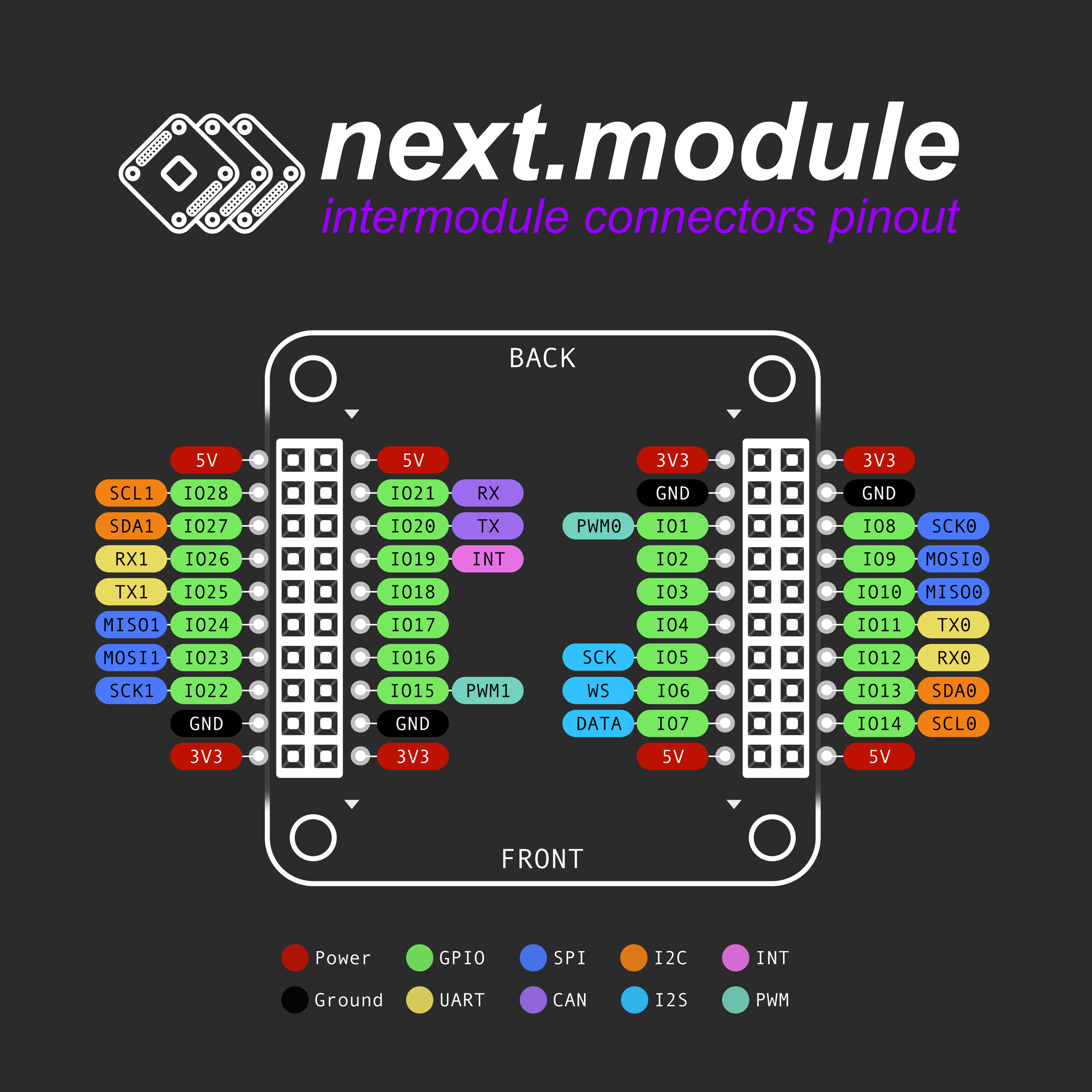
The connectors have power, ground, digital interfaces and several GPIO (general-purpose input/output) pins.
Which interfaces are available on the connectors:
- 2 x I2C (Inter-Integrated Circuit)
- 2 x SPI (Serial Peripheral Interface)
- 2 x UART (Universal Asynchronous Receiver-Transmitter)
- 1 x CAN (Controller Area Network)
- 1 x I2S (Inter-IC Sound)
The power, ground and main digital interfaces contacts are symmetrically located relative to the center of the PCB, which is necessary for the modules inside the device to be rotated 180 degrees. When the module is rotated, nothing burns, and modules using SPI, I2C, and UART will remain correctly connected to these interfaces.
I2C is the main interface for extending a device with modules. I2C is used by many sensors, RTCs, small displays, I/O expanders, and other chips that need to be configured using I2C. The I2C interface (I2C0 or I2C1) can be selected using jumpers on the modules.
SPI is used to connect displays, ADCs, DACs, interface modules based on controllers with SPI, radio modules, etc. The SPI interface (SPI0 or SPI1) and Chip Select pin can be selected using jumpers on the modules.
UART is used for RS232/RS485 interface modules, for GSM modules, for any other modules that use UART. The UART interface (UART0 or UART1) can be selected using jumpers on the modules.
CAN is used for the CAN interface module.
I2S is used for modules with audio inputs/outputs.
Unused GPIOs can be used as auxiliary signals (Data/Command switches in displays, Chip Select for modules with SPI, Tx/Rx switches in interface and radio modules, etc.)
Discussions
Become a Hackaday.io Member
Create an account to leave a comment. Already have an account? Log In.
Nice I wonder if it's worth adding PWM/INT/RST as a 'serving suggestion' on IO1, IO2,IO3 to give clearer compatibility with https://www.mikroe.com/mikrobus-shuttle
Are you sure? yes | no
You're right, I added 2 PWM pins and an INT pin to the pinout, and I also modified the schematic for the CPU MicroMod module.
Are you sure? yes | no