Hulk
HulkWhen you mix creativity with electronics, it becomes a masterpiece.
Producing something original and worthwhile leads to the creation of a number of great new useful household products.
In this video, I am going to show you guys how to create this Arduino based touchless concrete clock.
3D Design

I always love to generate a 3D model of my product before creating it in real. This not only gives me a better view of what the final product is going to look like, but also helps me in finding the correct measurements of the final product. So, I went ahead and used the free "Windows 3D-builder" to generate this 3D model.
The onscreen, black bar is where the TM1637 Digital Clock Module will sit. The gap in the circular concrete frame will house the 5 Blue LEDs that can be turned on or off my moving your hand over the IR Module.
These two holes are for the IR Sensor Module. The concrete base bar will house all the remaining electronics components in it.
The Template
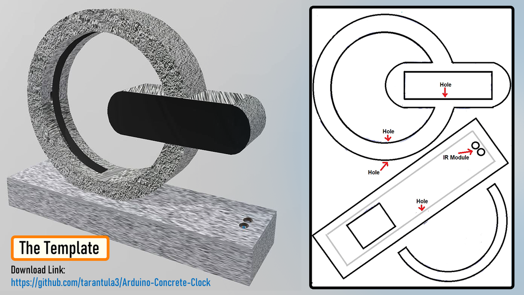
Based on my 3D-Model I designed this 2D-Template.
You can download the template from the link provided in the description below and print it on a A4 paper.
Template: Download
Schematic Diagram

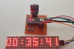
Before going ahead, lets have a look at the schematic diagram of the digital clock. The heart of this circuit is an Arduino Nano.
The TM1637 Digital Clock Module connects to D4 and D5 pin of the Arduino.
The DS1302 RTC Module connects to the A1, A2 and A3 pin of the Arduino.
The two White LEDs displayed on both sides of the digital clock connects to the D11 pin of the Arduino. These two LEDs flash 3 times every hour when the minutes counter is reset to "00".
The IR module is connected to the D6 pin of the Arduino and controls the blue cluster of LEDs connected to D12 pin of the Arduino.
My initial plan was to have 2 to 3 push button switches connected to D2 and D3 pin of Arduino to set the time of the clock. However in the final version, I did that by adding an extra line of code to my program. I will explain this in full details when we discuss the code.
Preparing The Top - Concrete

Using cardboard I created all the concrete molds. Cardboard was my first choice as it is very easy for me to cut and bend it into any shape of my choice.
These holes in the mold you see are for the ribbon cables.
Sticking this semi-circular piece on the left side of the inner circle will create the gap for the blue LED cluster when we pore the concrete into the mold.

Alright, so this is how it looks like after putting all the pieces of cardboard mold together. Now, lets pour some "Brickies Sand" in-and-around the mold to hold it nice and tight when I pour the liquid concrete. Making the sand a bit wet, will make it firm and will also remove all the unwanted air from the sand.

Cool, now lets go ahead and pour the concrete into the mold. Don't forget to compress the concrete mixture as you pour it. This way the concrete will reach all the necessary places and will also remove the unwanted air bubble from the mixture.

I also added few "Nails" inside the mixture to give it a bit more firmness. This step was absolutely necessary, as my first design completely collapsed because it was not very sturdy.
Once the setup dried up I removed all the sand and extracted the piece of art from it.
Preparing The Top - Electronics

Alright, now lets start installing the electronic components to the top section of the clock.
The 4-Digit LED clock module will sit inside this gap. I will cover it up using a black plastic film which I extracted from a wrapping paper.
For the back, I am using a compressed wood board. Based on my initial design I am going to make some holes in the board and install 3 x push button switches to it.
The blue LED cluster will be hot-glued in the gap at the back of the circular section.
I used a plastic cutout from a milk bottle to cover the Blue LED clusters. The white color of the plastic gave it a gloomy look, which was absolutely super awesome.

I...
Read more »
 Maarten Janssen
 Michael Wessel