Close
0%
0%

Accelerated Dice

A randomized dice using an Adafruit ATTINY85 breakout board, 8x8 LED matrix, and an accelerometer.

Similar projects worth following
For the 1Kb competition I wanted to do something fun and functional so I decided to make a N-sided dice with an LED display. I am using the following Adafruit components: MMA8451 Accelerometer Breakout, Mini 8x8 LED Matrix w/I2C Backpack, and the Trinket Mini (using the Attiny85). The Trinket uses a USB bootloaded since that is how it is programed but since I am not using any of those features in my project I think this is still allowed. This was programmed with the Arduino IDE and hopefully this code will work on other AVR devices.

I wanted to use an accelerometer to trigger the generation of a new dice number which gives a more authentic feel. Each dice roll will update the display with a new number (0-9). Even with the USB bootloader there is over 4k bytes of free memory that could be used to expand this system to use two or more digits, improve the randomness of the numbers, or special animations.

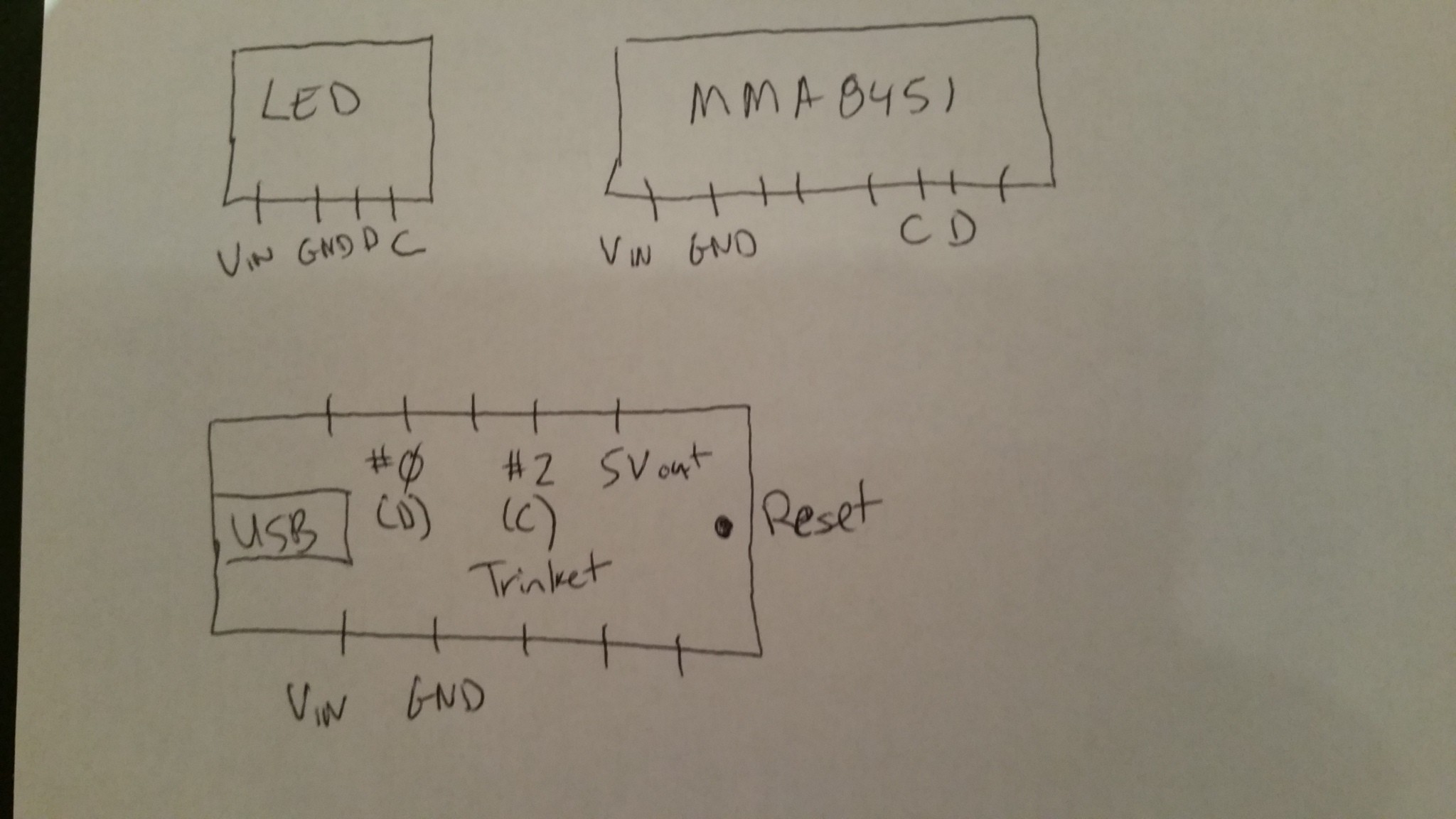
This project was for creating a dice that using an accelerometer would randomly generate numbers. The electronics were based on an Adafruit Trinket microcontroller, Adafruit 8x8 LED matrix, and an Adafruit MMA8451 Accelerometer breakout board. The programing was done with the Arduino IDE as the Trinket was comparable with that system.

To make the 1k limit, I needed to disable some interrupt code in the core Arduino code. This process was documented in the project log and software build instructions.

This dice works by using the face orientation of the accelerometer to detect rotations and trigger a new number generation event. I created a loop and checked for orientation changes for a set number of iterations. If the change threshold was met, the dice number was updated. To get a quasi-random number I created a temporary value and for each loop for the orientation check I added the loop number and the orientation enum value. This will be quasi-random because the dice roll will determine when the threshold is met and it would be hard to discern when this would happen. Its not perfect but uses very little memory and gives a pretty reasonable series of numbers.

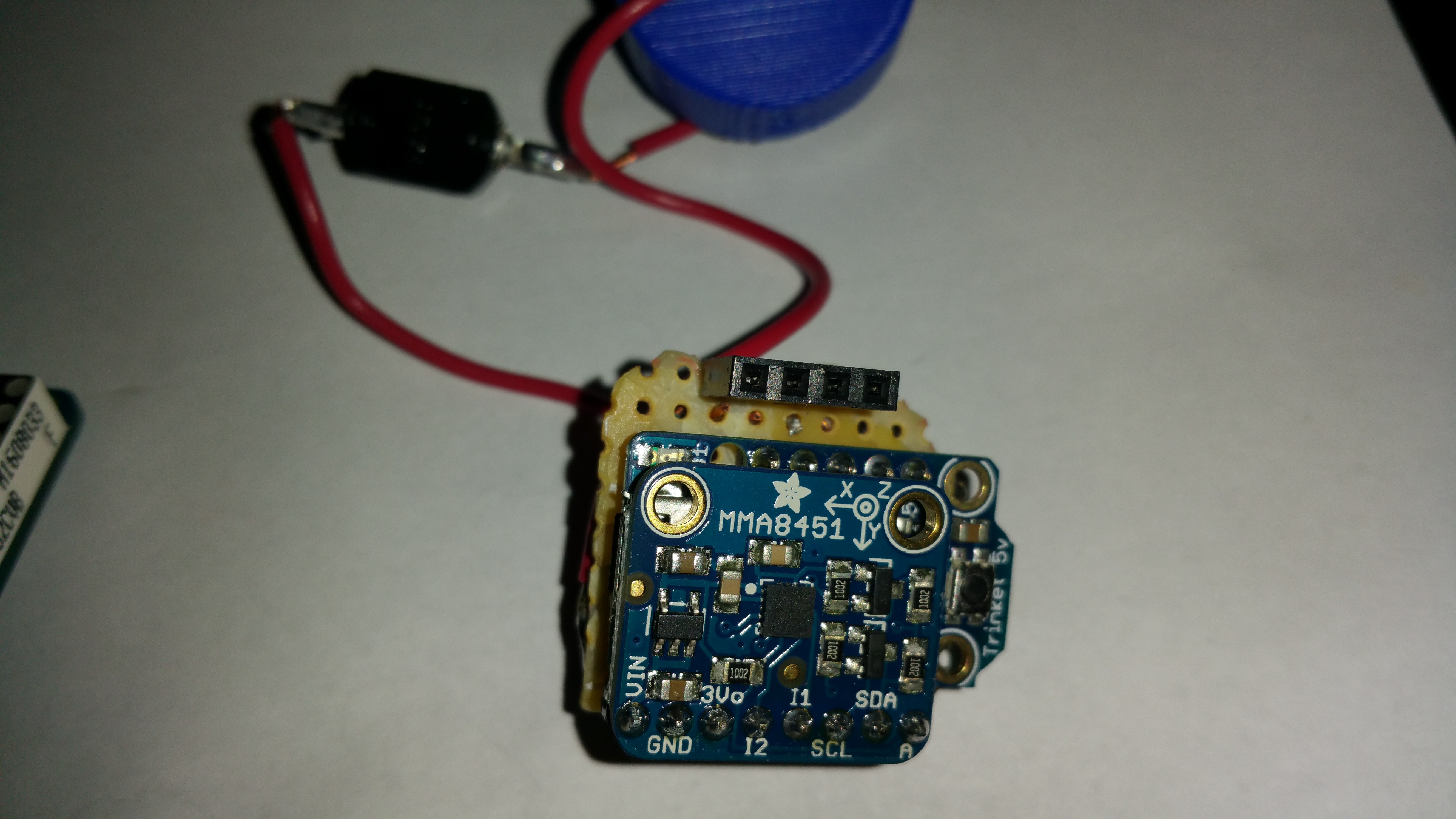
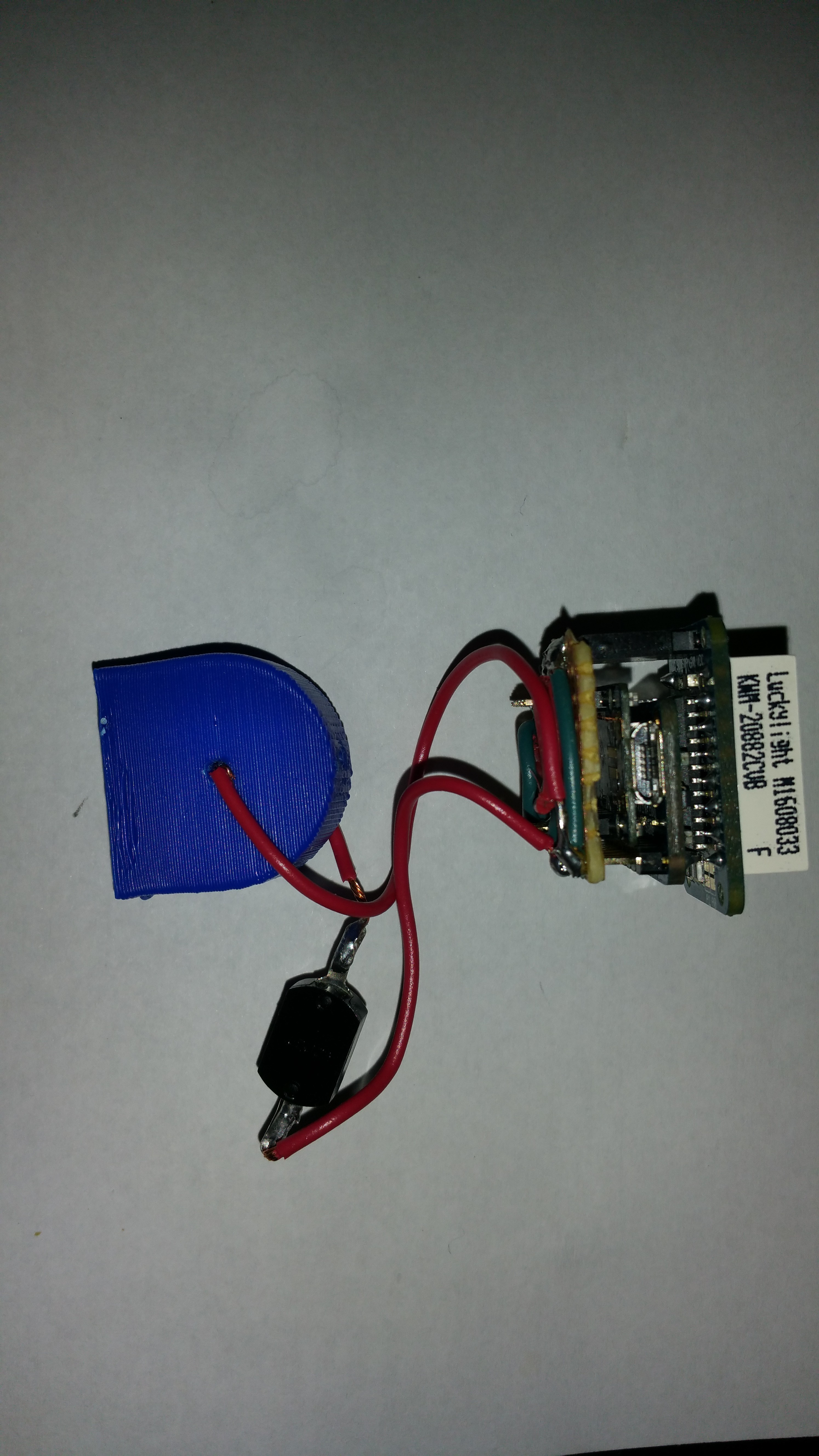
The dice is powered with two CR2025 batteries and has an on/off button. There is still a lot of the free space on device so a lot more features could be added. There is space on the matrix for at least two digit numbers and another button could be added to change the max number being generated.

Here is a video of the dice in operation:

https://drive.google.com/open?id=0B-pKTjS6J01NaHBHc2tzUFY1dmc

Code is posted at https://github.com/fsleeman/accel-dice.

ino - 4.41 kB - 01/05/2017 at 05:28

Download

scad - 8.89 kB - 01/05/2017 at 05:27

Download

View all 11 components

  • Completed Project Log

    Ford Sleeman01/05/2017 at 04:15 0 comments

    Instead of posting individual logs for the project, I am posting a single completed one. Below is the path I took while I was working on this project and the challenges I ran into.

    The first set of this project was to acquire the required parts which was easy since it was mostly from adafruit.com. Once I got the main components I tried playing around with the examples provided and was able to get the LED matrix and the accelerometer working together with little trouble. Next, I wrote custom code to generate the numbers displayed on the matrix as the Adafruit libraries, while user friendly, were way to big for a 1k limit.

    After it looked like this project was viable from a technical standpoint I started working on a 3D printed enclosure to make this a real dice that could be rolled. When all was said and done, I might have spend almost as much time on the enclosure design as the software and hardware. After about three iterations I finally got an enclosure that fit all the components reasonably well.

    Initially I was planning on using the raw accelerometer 3-axis values for triggering the rolling action. While this appeared to be working it took a lot of code a hundreds of bytes of data. Even resorting to a single axis did not save enough space since they were all using the same functions that had to compiled if they were used only once. Fortunately I realized that simply reading the current accelerometer orientation took much less code and ultimately is what I really wanted.

    After making these changes I will still around 1.2k bytes and with only a few more bytes to shave some space. After spending hours souring the internet for how to reduce the file size I learned that the Arduino IDE compiles a lot of extra stuff right from the start and interrupts were being implemented for a number of functions I was calling. Using a blank Arduino sketch for the Adafruit Trinket board with only an empty setup() and loop() functions the resulting sketch size was 286 bytes! That is over 25 percent of the total space I had to work with so it was obvious I had to go into the Arduino core code to remove unneeded code.

    When I was ready to start working on the Arduino code I realized I could not figure out where was the code to modify. I figured out that under the Arduino IDE File→Preferences there is an option under “Show verbose output during:” named “compilation”. This will spit out all of the build instructions including the library and core files used to actually create the sketch. In my case, the core code was under C:\Program Files (x86)\Arduino\hardware\arduino\avr\cores\arduino.

    The first thing I changed was to comment the init(); command from the main.cpp file. This function call initialized some interrupts which I was not going to use. After making that change the new blank sketch is now only 54 bytes! That huge saving is what I needed to make a respectable dice. I believe there are a few more bytes that can be saved, possibly from the Wire library, but this 200+ byte savings was enough for this project.

    When modifying the Arduino core code it important to remove the pre-compiled object files. Unlike the files in your sketch directory, the core code is not recompiled by default. The Arduino IDE uses a temporary build directory that can be found in the build log. This directory path will be something like C:\Users\{user name}\AppData\Local\Temp\arduino_build_81478. Under that directory are sub-directories named core and libraries. The core directory will need to be cleared when modifying Arudino core code and the libraries directory will need to be cleared when modifying an included library. Failing to do will use the old compiled object files.

    One strange thing I noticed was that when I modified the Wire library, or tried to completely break it, the compiled sketch did not seem to show the change. I was expecting the sketch to fail to compile at least since I purposefully added invalid code. Even though I modified...

    Read more »

View project log

  • 1
    Step 1

    Hardware

    The assembly of components is pretty straightforward, although it would be easier with a proper PCB. Below is a diagram showing the pinouts of the three devices. They are all well marked although its not clear right off the bat which Trinket pins are used for clock (C) and data (D).

    Below are some pictures of the assembled electronics.

    My wiring is kind of a mess since I didn't have time to make a PCB but it worked. You can't tell very well from the picture above but the MMA8451 board fits nicely right over the Trinket board. The 4-pin female header was used to mount the LED matrix board.Once everything is wired, insert the LED matrix in the top portion of the enclosure. The battery holder has holes on each side to run in wires. With about 0.5 to 1.0 cm of wire on the inside, the batteries when inserted make a good contact with the wires. Then align the power button and then close both sides and finally, bolt the two sides together.


  • 2
    Step 2

    Software

    In order for all of this code to fit under the 1k limit some of the interrupt code will need to be removed. The quickest and safest way to achieve this was to backup the Arduino code folder normally found in Windows under C:\Program Files (x86)\Arduino. With a backup copy it was safe to modify the code and still have a way to go back to the vanilla code.

    The following modification in the Arduino core code needed to be made to fit the 1k limit:

    (under C:\Program Files (x86)\Arduino\hardware\arduino\avr\cores\arduino)

    In main.cpp comment line containing: init();.

    This will disable a lot of interrupts not being used.

View all instructions

Enjoy this project?

Share

Discussions

Ford Sleeman wrote 01/06/2017 at 03:07 point

The number update is generated by counting the number of orientation changes in a fix number of loops (i.e. a cheap timer). Because how this was tuned tapping the dice or shaking it usually will not trigger a new number generation. The number of loops and the required number of orientation changes during the loops tunes when the display is to be updated. You could chance those if you want a slightly different behavor.

  Are you sure? yes | no

Isaiah Odhner wrote 12/30/2016 at 06:41 point

Ooh, this could be really cool if it could rotate freely in an enclosure and it was weighted so the display would always rotate to the top. I mean, sure, shaking or tapping would be more efficient, but I'd want to roll it.

  Are you sure? yes | no

Similar Projects

Does this project spark your interest?

Become a member to follow this project and never miss any updates