Background
We've implemented the Omniport interface, but how do we know it works? We can look at the signals with a scope or a logic analyzer, but the true test is to see if it works with a real live peripheral. Not having any MCM peripherals handy, that means we have to build one.
When it came to peripherals, MCM sold various kinds - a daisy wheel printer, a dual floppy disk drive, an RS-232 interface and so on. But they also sold a General Purpose Interface board ("GPI board" to it's friends) which interested customers could use as the basis for an interfaces to any device of their choice. The GPI board looked after the mundane "housekeeping" logic of device addressing, device selection and conveniently breaking out various signals. The customer then provided the rest of the interface to their chosen device.
I don't have a photo of an MCM GPI board but, instead, here is a photo of the MCM RS-232 interface which is based on the GPI board:
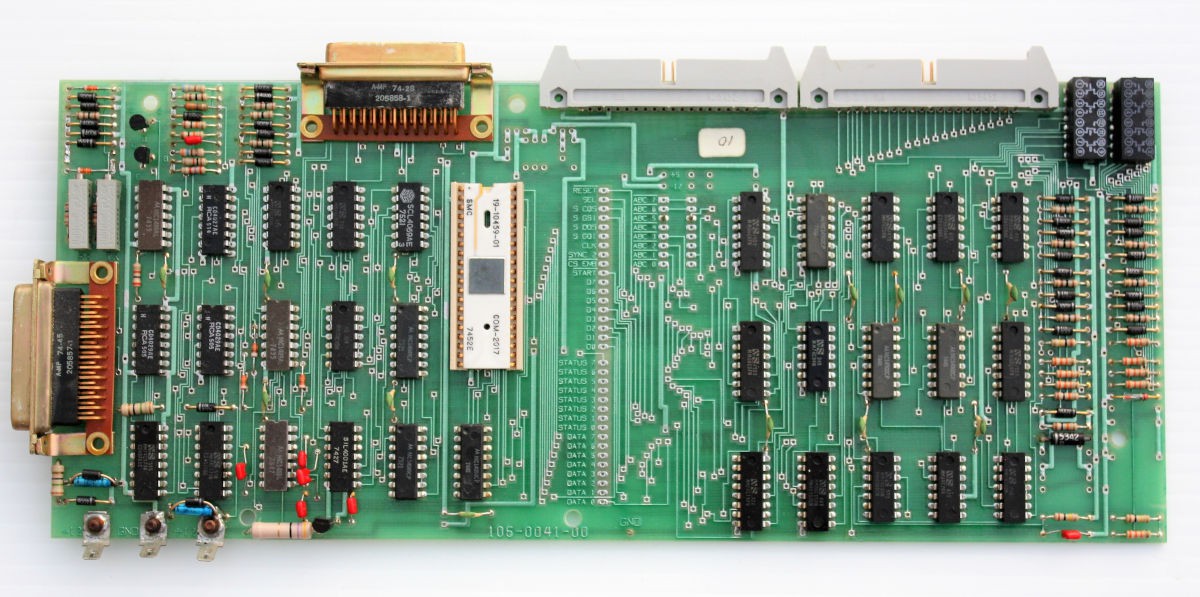
The left side of the board is the actual RS-232 interface logic. The right side of the board is pretty much the GPI board verbatim. Which is to say that when it came time to create the RS-232 interface MCM simply took the GPI board and glued the RS-232 specific logic on the left side. On an actual GPI board the left side was a prototyping area for the users chips.
The vertical row of oblong pads down the middle of the board is where the GPI section of the board provides the broken out signals.
The one and only MCM schematic diagram that I happened to have is of the GPI board, dated 1975, here:
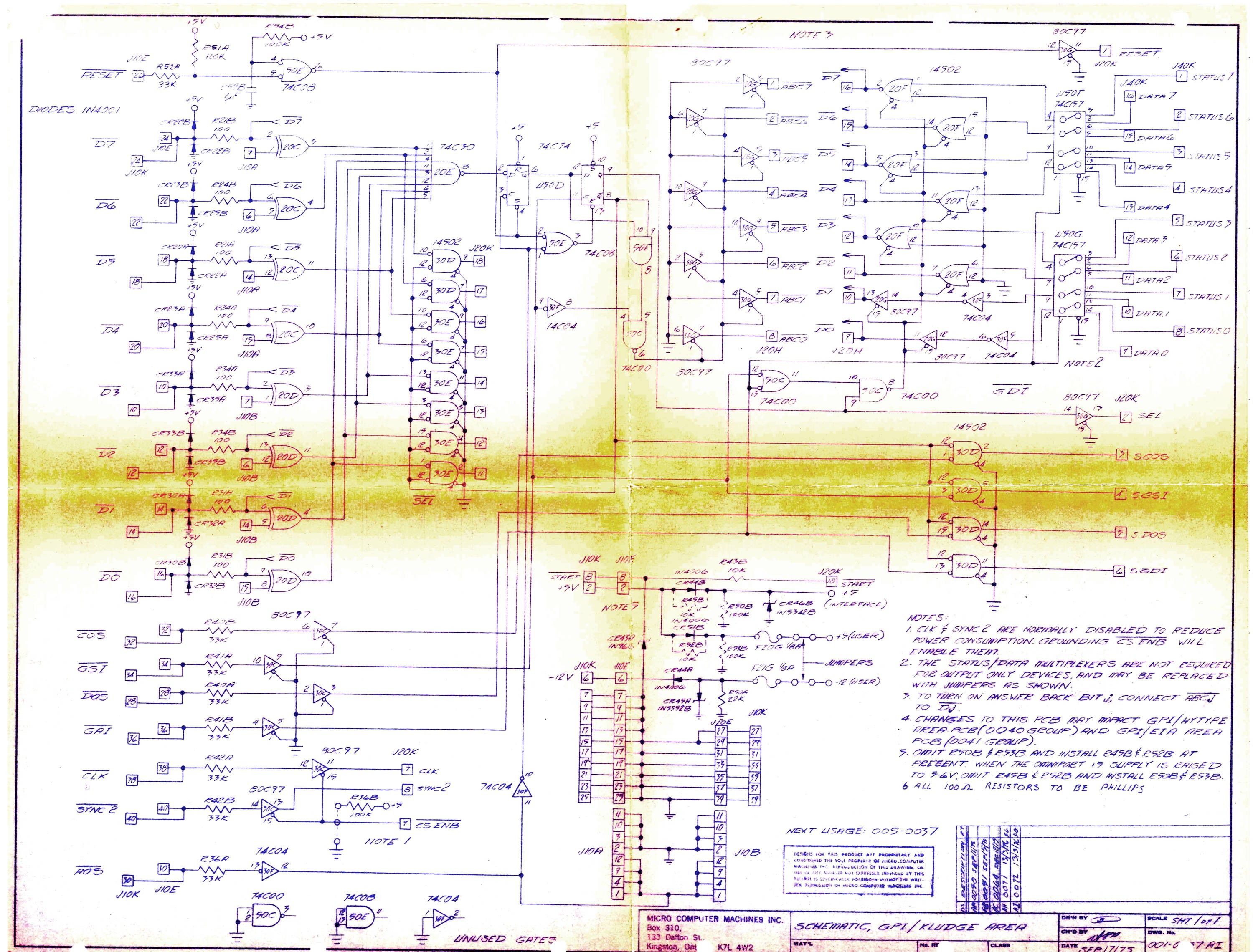
In aid of keeping power consumption down it's all CMOS chips but given that this was in the relatively early days of CMOS some of the chips are unavailable and for others there are now better choices. I did a pretty literal transliteration of the MCM schematic,mutatis mutandis, and came up with this schematic for the Rack8 project's version of a GPI board.
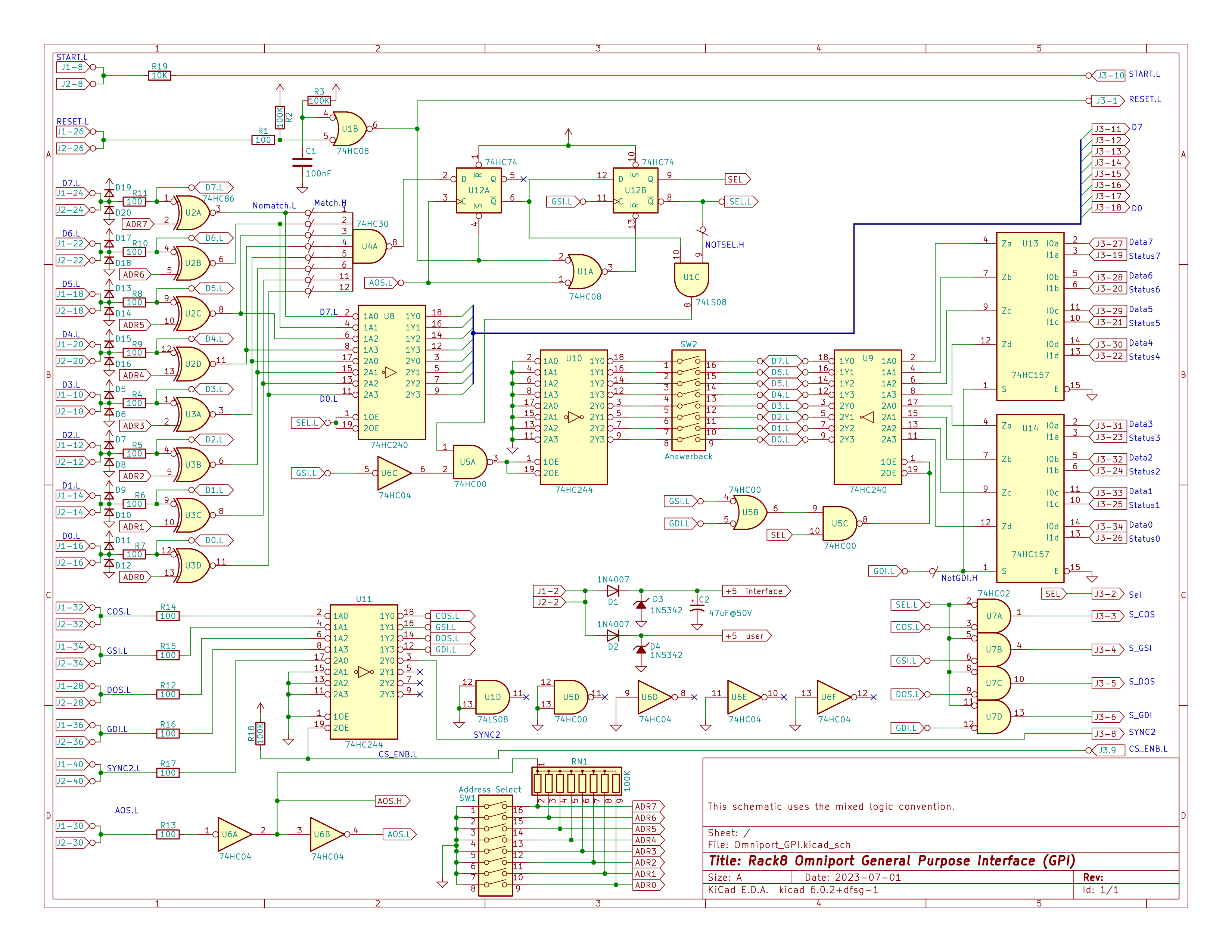
The omniport lines from the computer come in on the left, while the various lines to and from the users interface are on the right.
How the Omniport works
An MCM document "STANDARD OMNIPORT INTERFACE - Preliminary System Documentation" is HERE.
Each Omniport device has an address. Addresses can range from 1 to 255; address zero is reserved for the keyboard/selfscan device. On the Rack8 GPI board, above, the device address is set by DIP switch SW1. The MCM/70 computer selects a particular device by putting the address of the device on the Omniport data lines and then pulsing the Address Out Strobe (AOS) line. This deselects all connected devices, and puts the addressed device in what we might call the "preselected state". The Gate Status In (GSI) line is normally used to fetch a byte of status information from the device but, for the pre-selected device, the first GSI following an AOS returns the Answer Back Code (ABC) of the device. At that point the device is now fully selected. On Rack8 GPI board the answer back is set by DIP switch SW2.
The Answer Back Code is an 8-bit value which supplies some information about the peripheral. The X'80' bit is true for devices that can do input. The X'40' bit is true for devices that can do output. The X'20' bit is true if the device is interactive (i.e a terminal) while the remaining five bits are a code which identifies the particular device. Some known MCM device codes:
- 0 - EIA/ASCII terminal
- 1 - MCM cassette drive
- 2 - MCM/Hytype daily wheel printer
To send a command to the peripheral the MCM/70 puts the command bits on the Omniport data bus then pulses the Command Out Strobe (COS) line.
To send a data byte to the peripheral the MCM/70 puts the data bits on the Omniport data bus then pulses the Data Out Strobe (DOS) line.
To read the status byte the MCM/70 pulses the Gate Status In (GSI) line which prompt the peripheral to put its status information on the Omniport data lines.
To read the data byte the MCM/70 pulses the Gate Data In (GDI) line which prompts the peripheral to put it data information on the Omniport data lines.
And finally there is the Reset line which, when pulsed, tells all peripherals to reset themselves to their default state.
Discussions
Become a Hackaday.io Member
Create an account to leave a comment. Already have an account? Log In.