 Jerry Biehler
I got another turbo pumps, this time a complete set, pump and controller. It is an Osaka Vacuum TG2003 rated for 2000l/s at 24,000 rpm. It is mag lev like the other pumps I had been trying to get going but a little more friendly. I plan on keeping an eye out for another controller for the other 2000l/s pump I have.
So, to get this thing on the system is going to take quite a bit of modification. The rotary pump/blower package is going to come off the frame to get the vibration isolated from the turbo. I am also installing a stepper driven gate valve from VAT with a adaptive pressure controller. The gate valve mounts directly to the ISO250K flange on the turbo and receives feedback from a capacitance manometer on the vacuum chamber. The controller can be set for a pressure and the controller with open or close the gate valve to maintain the set pressure in the chamber. Pretty handy for sputtering and plasma processes that work above the high vacuum range.
All of this needs to mount where the diffusion pump was. That was mounted to the system through a 6" port with a ASA flange and a 6" pneumatic gate valve in between. I am leaving the gate valve in place, it closes very quickly and will be useful to cut off the turbo in case of a high pressure event. The stepper driven valve won't be of much use for this, it takes up to 10 seconds to close.
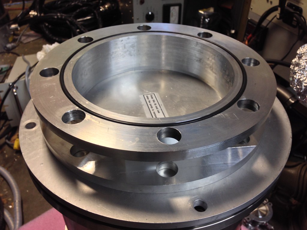
To mount the pump/valve to the existing valve I need an adapter that will go from the ISO250K on the stepper valve to the ASA 6" on the pneumatic.
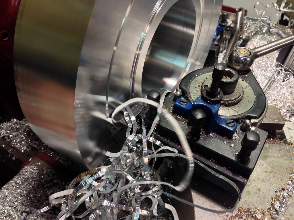
First step is to make a ASA 6" non-threaded to non-threaded flange. To make this I used a 11.25'x2.25" disc of aluminum with a 4" hole in the center I found on ebay. I chucked it up in the lathe and faced one side and then flipped it over and faced the other. I then ran into a problem. I do not have enough travel in the cross slide to cut out the aluminum to create what would be the flanges. I decided I would figure out a way to do that on the mill. Putting that aside I cut the two grooves for the o-rings that will seal this to the valves. If all possible you always want to cut o-ring grooves with a lathe or a trepanning tool, the scratches in the cut will be with the length of the o-ring and create a better seal, milled o-ring grooves can leak. To cut this I used my threading tool holder with a 1/8" wide grooving insert.
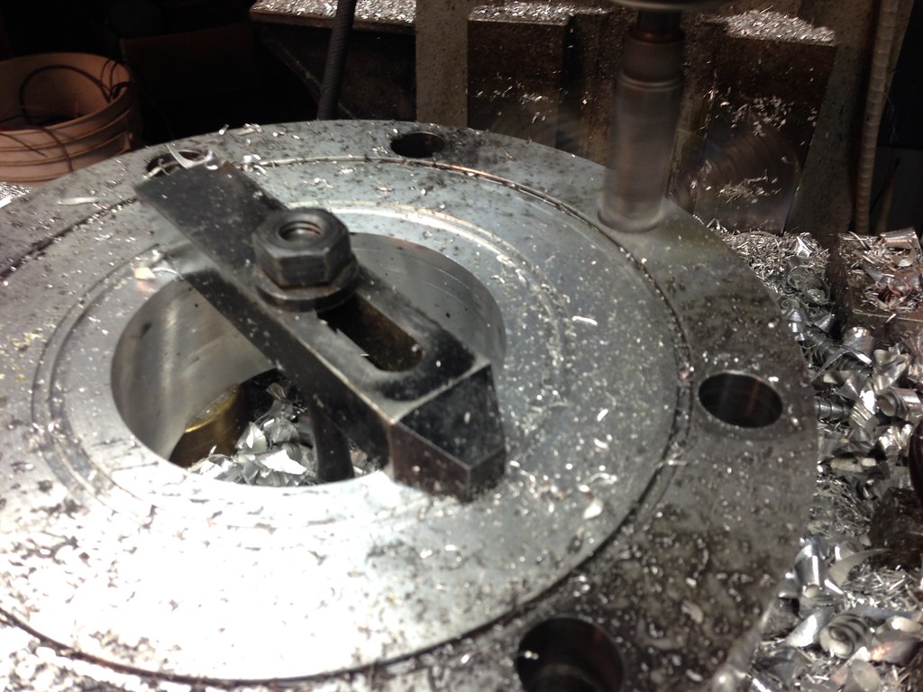
 With that done I put the ring on parallels on the mill table and secured it with a stud to the table. I used the mill to clean up the perimeter of the disc to 11" and then drill eight 27/32" holes for bolts.
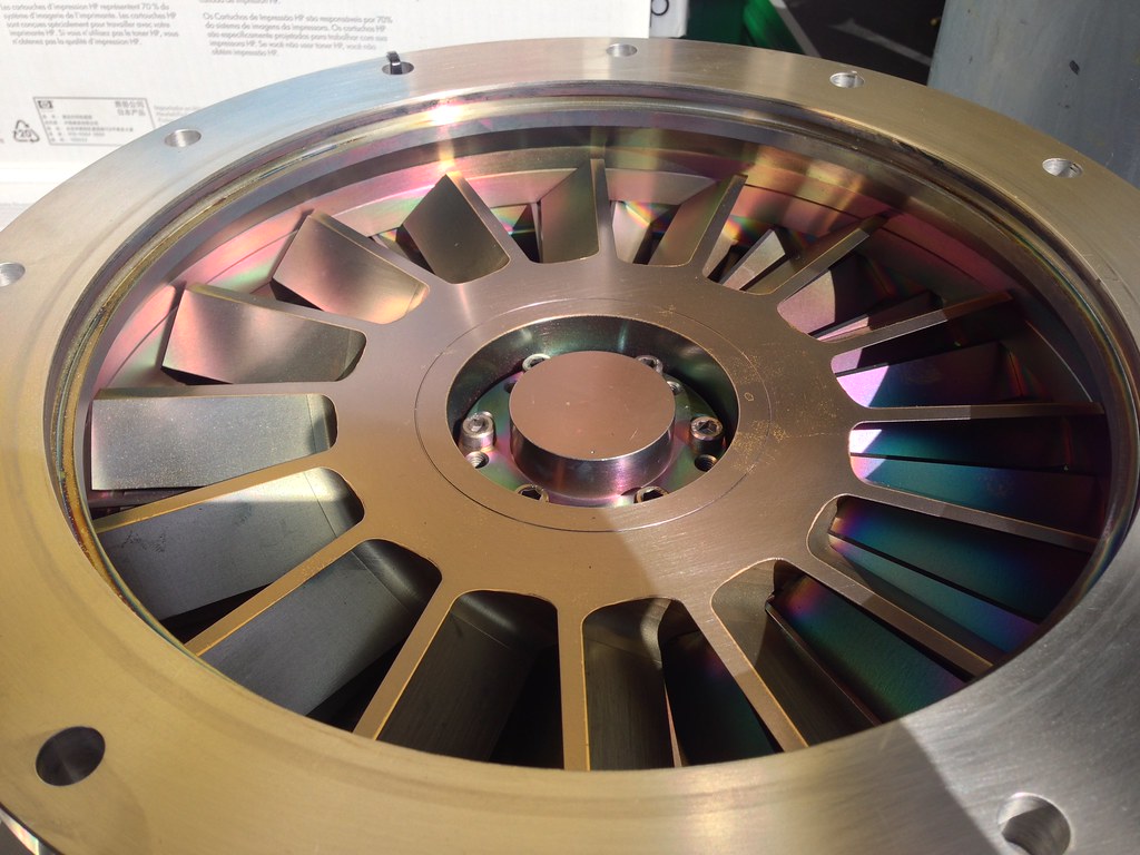
 To cut the flanges out I put the disc on edge on the table and use the shortest 1" cutter I had and milled out the groove 1.55" in from the edge at each bolt hole. Finally I clamped it back down to the table and programmed a tool path to cut out the remaining material in the center of the ring which finished this part. Next will be to make another adapter, this one will go from the ISO flange to the ASA flange, but I need more aluminum for that.
Discussions
Become a Hackaday.io Member
Create an account to leave a comment. Already have an account? Log In.