 Kevin Santo Cappuccio
IGV1-16s and also Burroughs Self-Scan
Here's a quick overview of how these work. This is how I understand it and could totally be wrong, but at least I was right enough to get it to work.
I'm writing this because a lot of the descriptions of the theory of operation seem to be written in stuffy-1960's-engineer-in-a-suit speak, and they aren't really clear about why anything's happening, they are usually more concerned with how to get it to show stuff. The should really be called Practicalities of Operation, amirite?
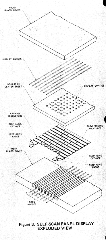
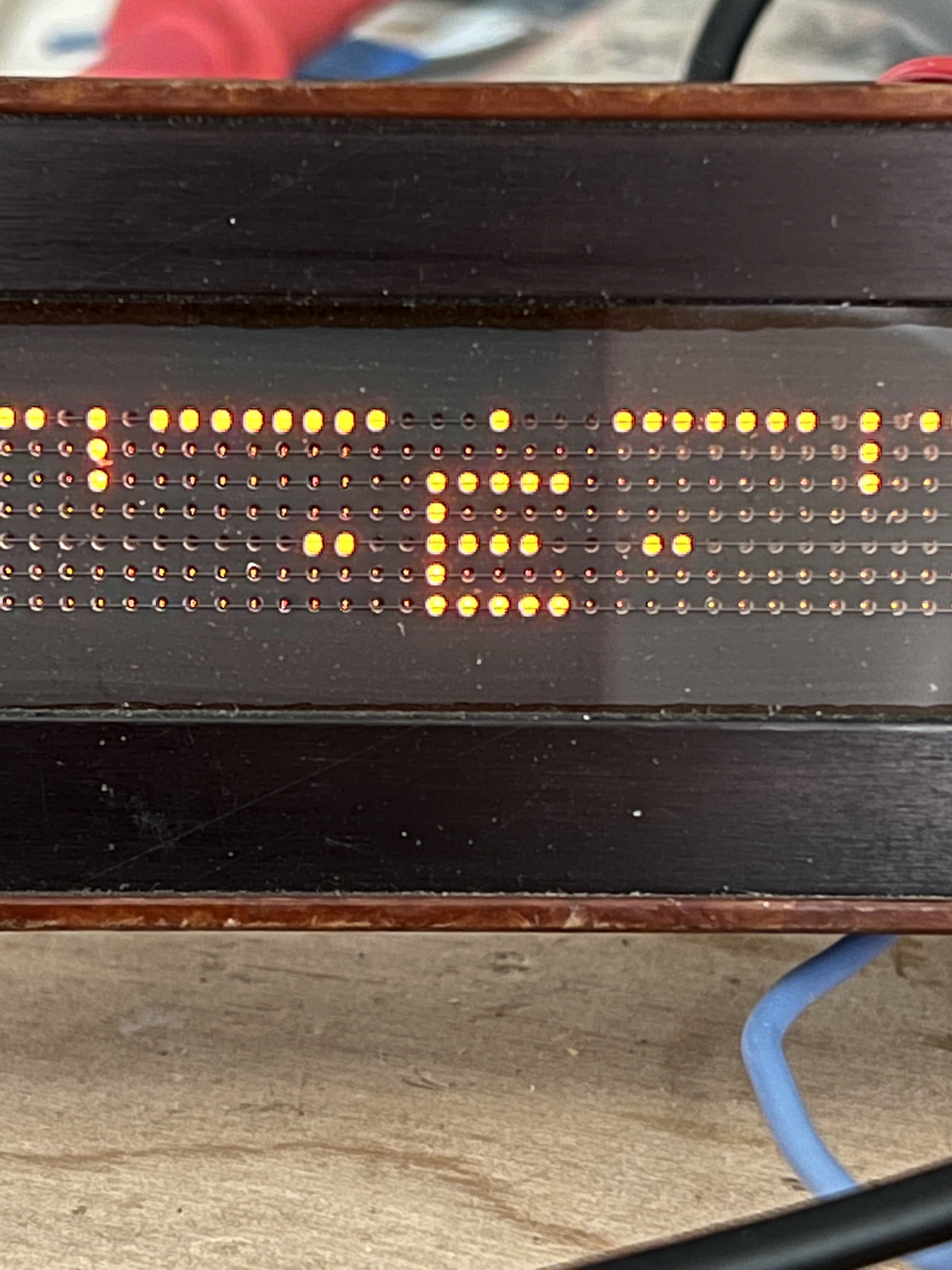
Here's what all that looks like in real life. Notice the plasma dots are still lit up behind the Insulation Center Sheet.
We have 7 Scan Anodes that run longways down the length of the display, and they're held at 250V. That's enough voltage to each make a single dot of plasma between the Scan Anode and the Cathode in the thin (almost vacuum) neon atmosphere inside. That dot of plasma will be at the nearest Cathode that provides a path to ground, the other nearby Cathodes stay at 82V, which is 82V less enticing to the plasma.
When we pull the Reset Cathode all the way to ground (it says -100V but ground seems to work if you give it more time at ground) that's a better path to ground than the 82V on the other Cathodes, so now we have all our plasma dots lined up on the left side of the display.
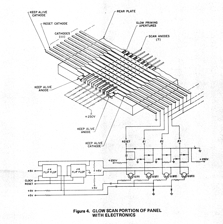
(The display anodes are not shown in this diagram)
Now we stop pulling the Reset Cathode to 0V and pull the first set of Cathodes down to 0V, this makes the whole column of 7 plasma dots move over to the next Cathode. You see in the diagram that every 3rd Cathode is wired together, we can do this because the plasma dots aren't going to skip over the nearest Cathode to get to the next one, which is great because otherwise we'd need another 108 wires going to the display for each Cathode.
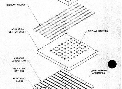
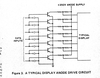
So cool, we have a column of plasma dots that we can move along the display, but we're still not showing anything because the plasma dots are still behind the Insulation Center Sheet. To light up a dot that can be seen on the display, we have to drive the corresponding Display Anode to an even lower voltage to suck the plasma dot through the Display Cavity and onto the front of the Insulation Center Sheet*.
So in the end, here the sequence:
move our row of plasma dots one column
drive the Display Anodes to show the pixels we want
wait ~200 uSec for your eyeballs to slurp up those photons
*do the previous 3 steps 111 times until you reach the last column*
pull the Reset Cathode low to bring the plasma dots back to the left column
*repeat*
Here's all that in Timing Diagram form
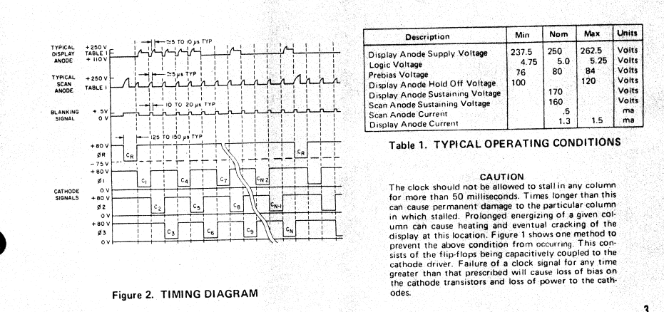
So yeah, this thing is a Persistence-Of-Vision display, which makes it really hard to take nice pictures and videos of the car compass. I promise it looks way better in person.
*in reality the plasma dots are being pushed away by the Display Anodes because they're pulled to 250V at rest, but I think looking at it as High Voltage -> Medium Voltage, Medium Voltage -> 0 Voltage is much easier to conceptualize.
Here's a page with links to all the datasheets I'm referring to:
http://ferretronix.com/tech/nixie/self-scan/
Discussions
Become a Hackaday.io Member
Create an account to leave a comment. Already have an account? Log In.