Kevin LO
WARNING:
Do not try to take measurement on the receiver when it is plugged into main power (110V - 220V), you may have chance get electric shock. Unless you have good knowledge to do it and you know what you are doing.
There are so many wireless doorbell in the market. Some of them saying that the doorbell is battery-free. Normally, the receiver requires AC110 - 220V power source. The transmitter is just a BIG button. Here is an example :
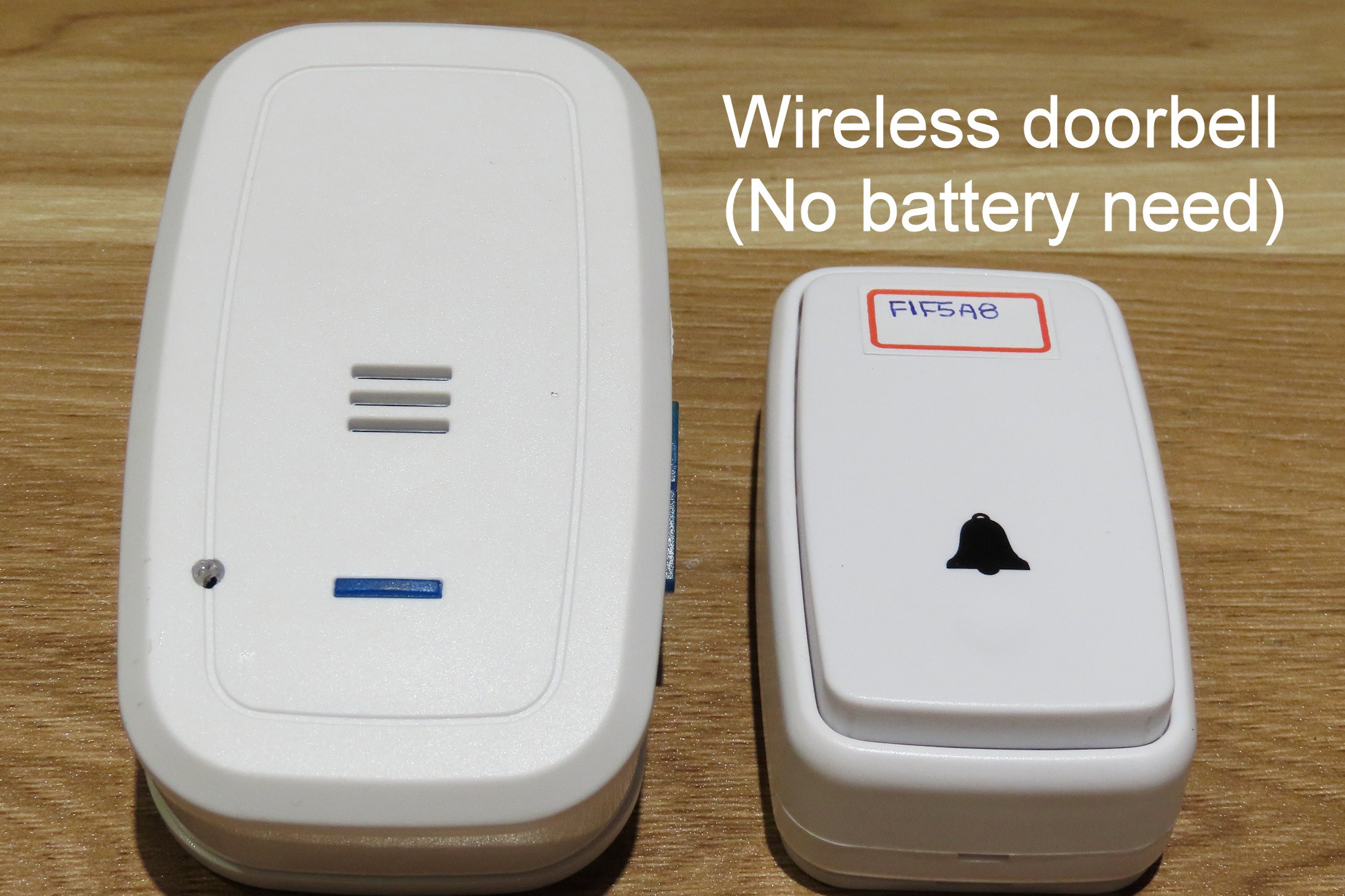
For the BIG button, when you depress it, it can converts this mechanical movement to electric energy. This electric energy can last for at least about 25ms in time, in which allows the transmitter broadcast its ID in radio frequency four times. Luckily, the doorbell use a separate PCB as RF module. It's working voltage is at 3.3V.
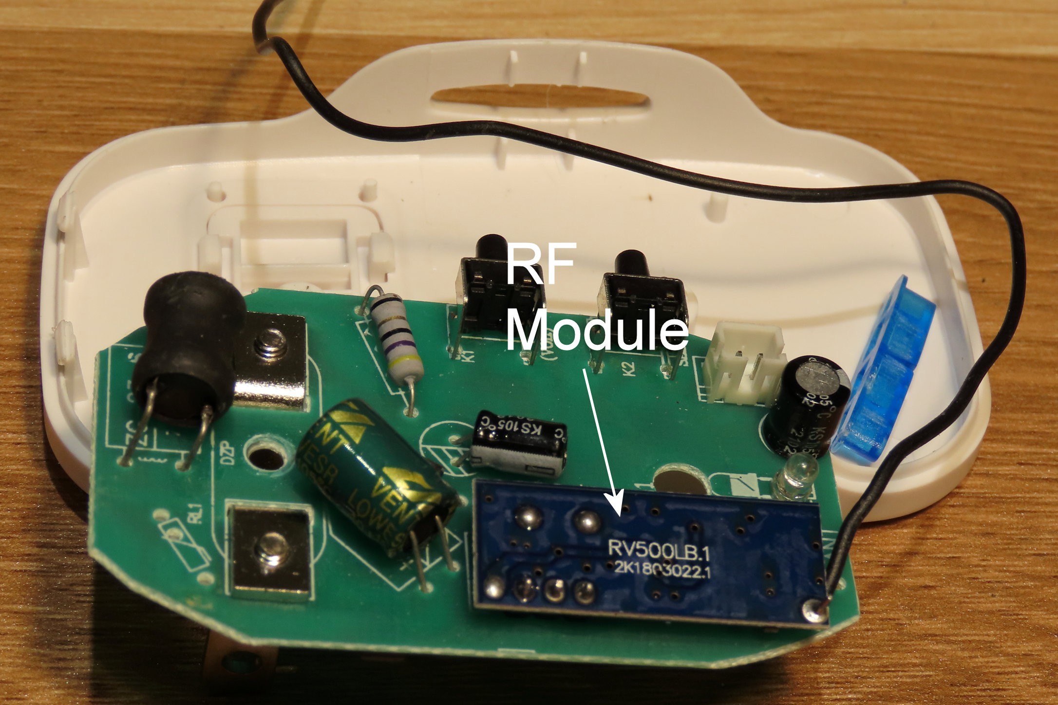
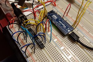
So just de-solder it and connects to the ESP32 board for RF data decode. I use a e-Ink ESP32 PICO module as example. It can show you the result directly.
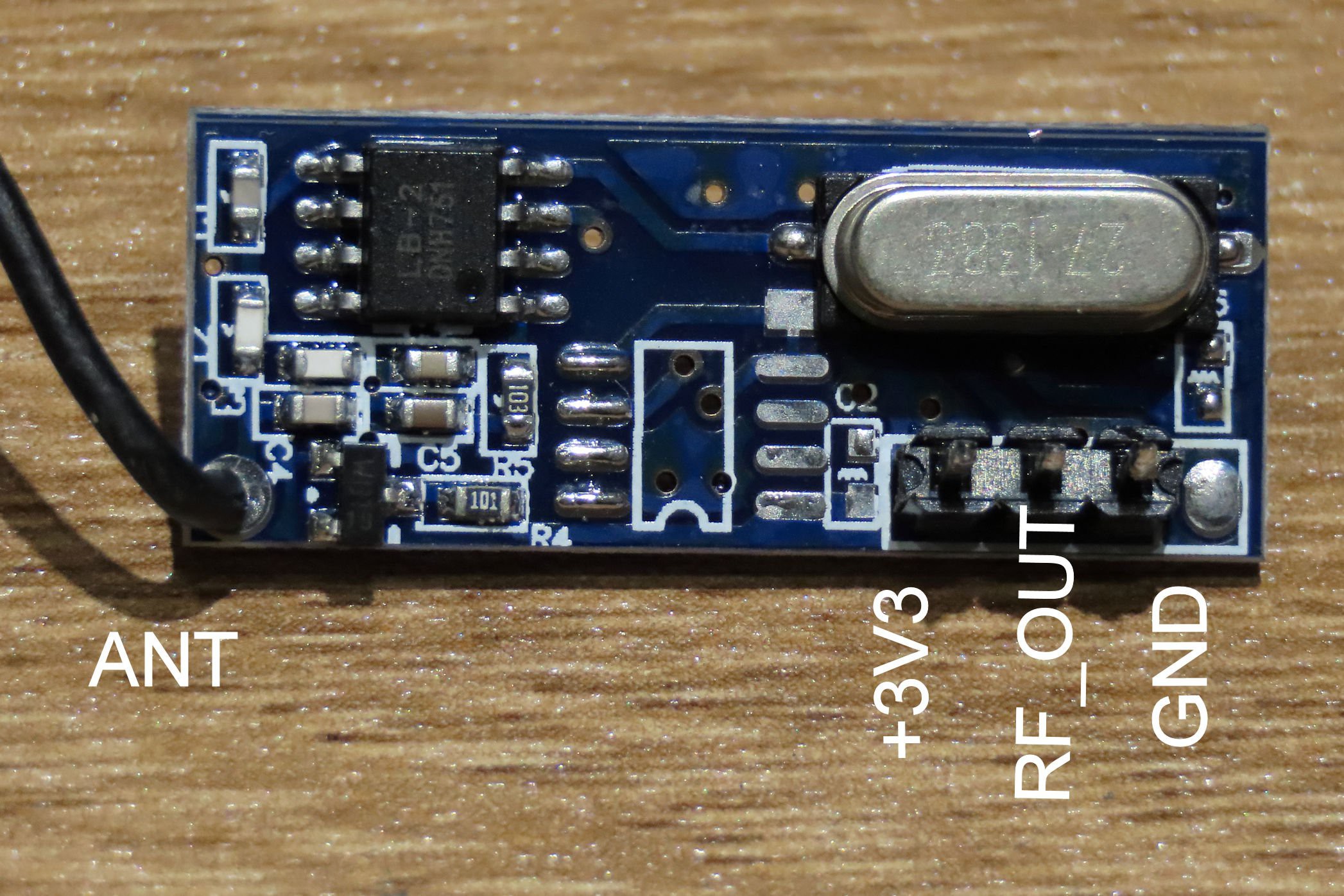
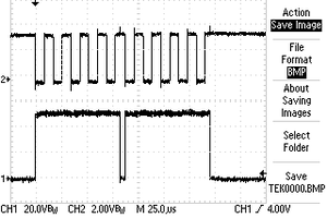
Now, it's time to use oscilloscope to see what's going on at the RF_OUT pin. The RF module connected to Arduino board with +3.3V, GND and the RF_OUT signal connects to IO21. Here we have the captured digital waveform :

The RF_OUT signal changes randomly when the power is on. It is something like White Noise, or when your radio doesn't well tuned. However, if you press the doorbell button once, you may see the pattern looks consistency and repeatable. There are four same 25-bits pulses occur, shown in yellow color at CHANNEL 1. For the CHANNEL 2, it is a debug signal done by the Arduino code. It is in-sync with the data stream where decode is take place.
Just zoom in the repeat pattern, you may see that if we sync every pulse with rising-edge, the time duration is almost the same. There are two types of pulse with different logic HIGH time duration. This is kind of PWM (Pulse Width Module). Assume that the pulse with short duration is binary bit '0' and the other is '1'. Then, we have 25-bits data "0 1111 0001 1111 0101 1010 1000" (00F1F5A8 in HEX). Already decode that bit stream? Yes. To correct decode these bit stream, we also require to determine the beginning of bit stream. For the waveform capture, there is a long duration low level pulse as indication.
For the Arduino code, we need to :
a. Determine the beginning condition of bit stream
- look for falling-edge of the signal
- measure duration of logic LOW level
- if it is about 1ms, then 'Start Condition' found
- otherwise, re-scan again
b. Determine each bit duration and decode it
- look for rising-edge of the signal just after falling-edge of 'Start Condition'
- delay for about 60us, that is somewhere in the middle of data bit time duration
- then, take reading of RFIN_PIN's logic level. If it is at LOW level, take '0' as reading, otherwise it is '1'
- shift and rotate bits to left in a double-word
- is it 25 bits done? If yes, keep this double-word content and wait for another 'Start Condition'

CHANNEL 2 shows you more precisely how the program works. The I/O pin ISR (Interrupt Service Routine) triggers when rising-edge of RFIN_PIN. The DEBUG_PIN sets logic HIGH when rising-edge detected. It will put into logic LOW level in the timer Alarm ISR when the program take readings on the RFIN_PIN for bit decode.
Since the data streams repeat four time, we may say that if there are at least two same doorbell ID code detected, we can confirm that the corresponding doorbell 'BIG' switch is pressed. In real world, RF signals may affected by weather condition, distance in between receiver and the transmitter, something blocked the RF signals such as wall etc. So you may not receive all four data pattern all the times.
So now, we can identify each RF switch ID correctly. You may now use this RF switch to control any devices.
A video shows captured RF data stream:
A video shows the decoded information:

 Jac Goudsmit
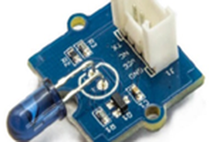
 pammyleong