 nullvalue
The MEGA Omega
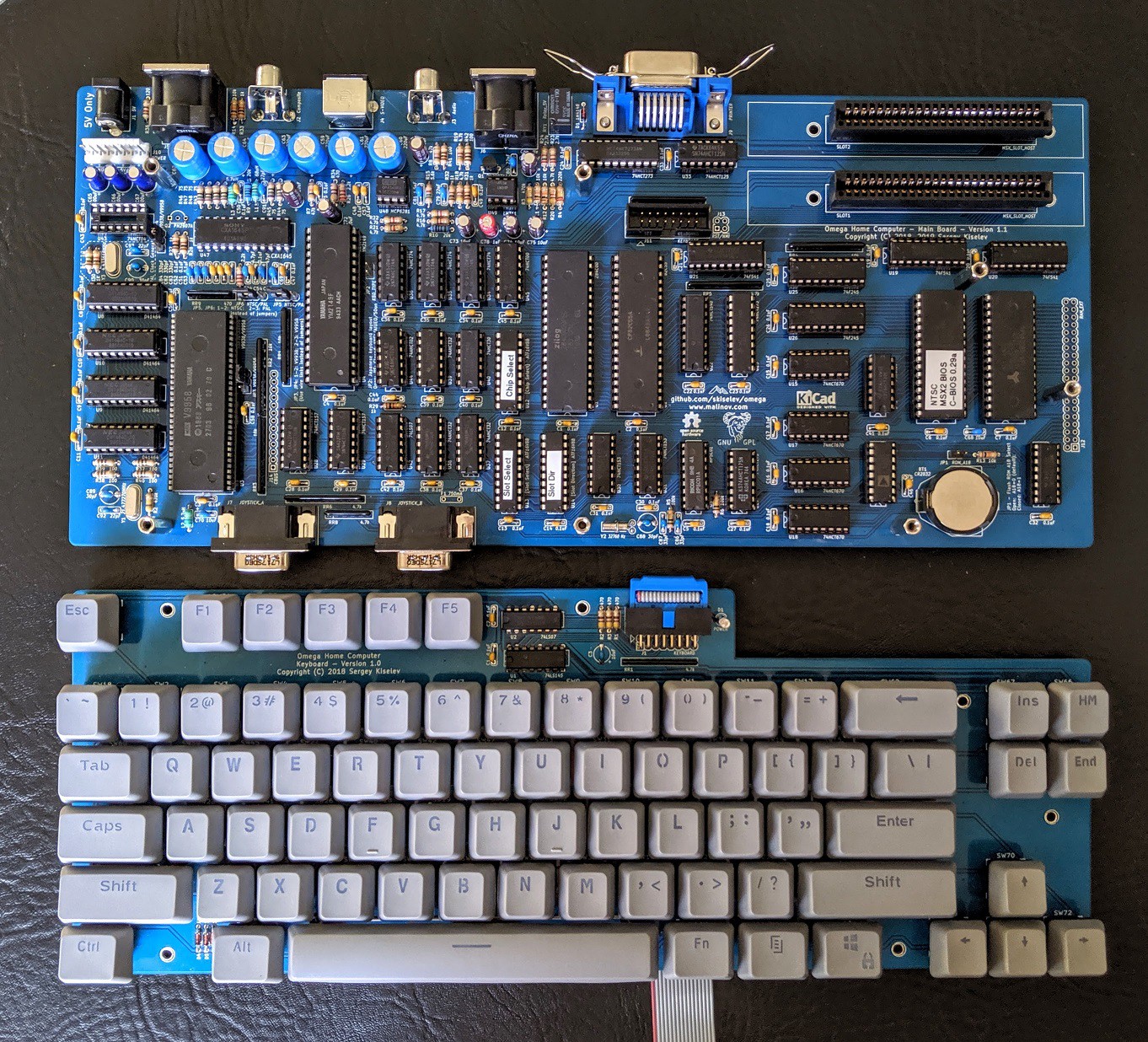
This is my over the top, no expenses spared, everything and the kitchen sink build of an Omega Home Computer.
 |  |  |
 |  |  |  |
Why MSX?
This story began a few years ago. See, I've been a programmer for some 25 years now. I've developed mostly business software using high-level languages either on Windows or the Web but I've always had an interest in how computers work deep down in their guts. In all this time I had never put aside the time to learn. Over the past few years I had began collecting some vintage computers and learning more about how they worked. While restoring a couple of late 70's S-100 bus computers, I've learned a lot of bus timing, memory management, and the Z80 CPU. Then COVID hit and I found myself with plenty of free time, so I taught myself x86 assembly. Finally with what I felt was a good enough understanding, I began thinking about designing my own single-board computer. What components would I use? Well I definitely knew I'd want to use the Z80 CPU. I had a TI-99 4/A computer had read about the flexibility and longevity of the Texas Instruments VDP-series video chip. I discovered this video chip and CPU combo was also found in the ColecoVision - one my favorite childhood consoles). For sound, I looked to the Atari ST which I knew was favored among early digital music producers and featured an excellent sound chip, the AY-3-8910 aka YM2149F. In researching all of these components, I was surprised to not only had there already been a computer released with these same chips - but that it was actually a whole computer standard called MSX - and there were dozens of different models produced. I knew I had seen the name "MSX" before while browsing emulator/ROM packs etc but never gave it much thought. As an American, MSX computers never made much of a dent here so I had barely even heard of them. Now I was intrigued, and in my searching learned that someone had recently designed a whole new MSX-compatible computer using mostly original parts called the Omega Home Computer. This project was created by Sergey Kiselev, and he has completed a number of other retro single board computer designs.
 |  |
The "Plan"
I downloaded the gerber files and ordered the two PCB's from JLCPCB. I know there a number of proto-pcb places around, but I've always had good luck with them and for the price they can't be beat. I ordered all of the passive components from the BOM from Mouser and ordered all the IC's from an eBay kit. However this kit doesn't include the V9958 VDP chip, which I ordered a different eBay listing.
So I got in all the parts and starting thinking about how I wanted the finished computer it to look. There is an acrylic case design and a number of 3D-printed cases available, but I really wanted to make this my own. Most of them are based on the keyboard-computer shared with most of the MSX computers and home computers of the 80's.
Now, I realize the may be sacrilege in some circles, but I have never been a fan of "wedge" style computers. I can't stand how cords seem come out from every direction of the computer, or how there's no good way to place a monitor near the computer.
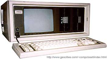
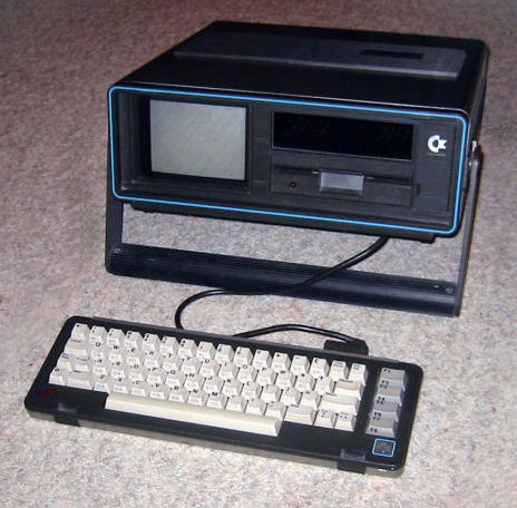
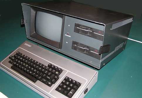
As impractical as they are from a modern perspective, I have always loved the "luggable" computer form factor. I remember being in awe the first time I saw a Compaq Portable. I also have a Kaypro IV '84 and a Commodore SX-64 in my collection. These were inspiration for my build. I started looking for an enclosure I could use but couldn't find one and the project kind of took a back seat for while.
Compaq Portable II
 | Commodore SX-64
 | Kaypro IV
 |
Then last year I attended VCF Midwest. What a cool experience, so much to see - I'm definitely going back. Outside the main show floor is a vendor area with people selling all sorts of vintage computer equipment. There, on the ground tucked under a table I saw this empty enclosure. Even though it didn't have a handle, I thought it would work for my build one way or another. It was a little larger than I wanted - I had planned on using a 5" CRT, but was hoping the larger size would allow me to use an 8" CRT instead. After a little haggling, it was mine for a whopping $30.
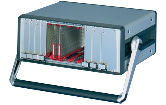 | This is a nVent Schroff 4U 84HP enclosure - it has a beefy industrial-grade build quality and would have cost over $250 new. I did however have to break down and pay like $70 for the handle kit. Ouch. Overall though, a pretty good deal. This type of enclosure is designed to be modular and customized to fit your purpose. It comes just as an empty case and you add components like dividers, handles, panels, etc. |
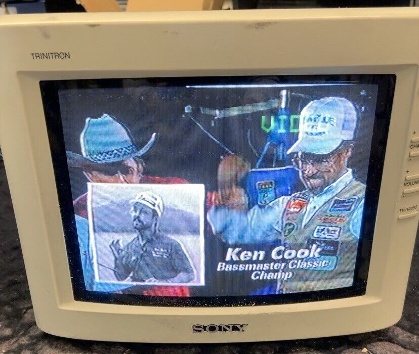
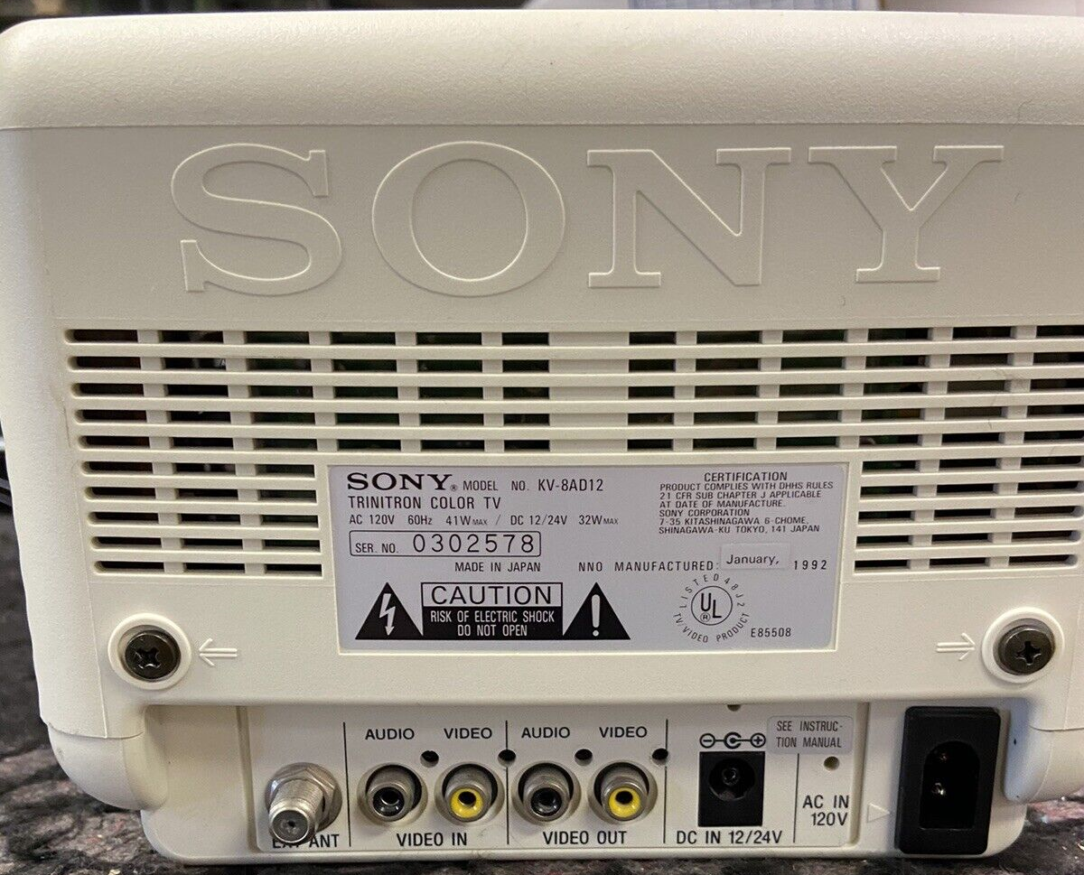
Now I had to decide on the screen. I definitely wanted it to be a real CRT, not an LCD. The Omega has the ability to output video as RGB, S-Video, or composite. I started looking for 8" CRT's which supported RBG but those basically put you in the category of PVM/BVM's. They're large and very expensive. I knew I'd have to remove it from it's case and remount it, so really didn't want to try that with a $400+ PVM. Next best option something S-Video capable, but I couldn't find any portable 8" TV's which natively supported it. I did, however find the Sony KV-8AD12 which had a known S-Video mod available. This would be perfect... It had a built-in sound amplifier for the speaker, capable of running on 12VDC and with a Trinitron tube, figured the picture should look pretty good. After some eBay searching, I picked one up for about $100.
 |  |
The Build
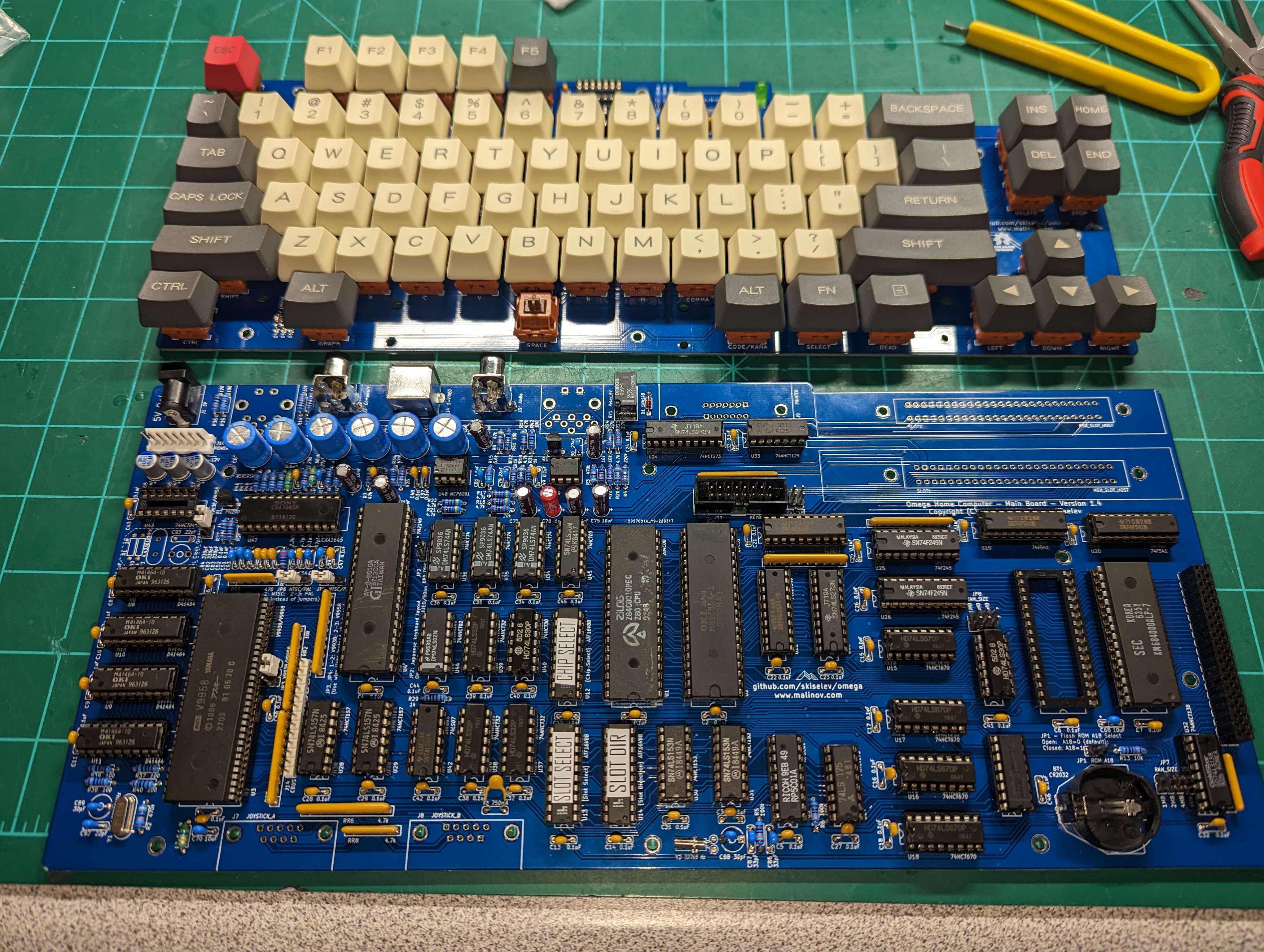
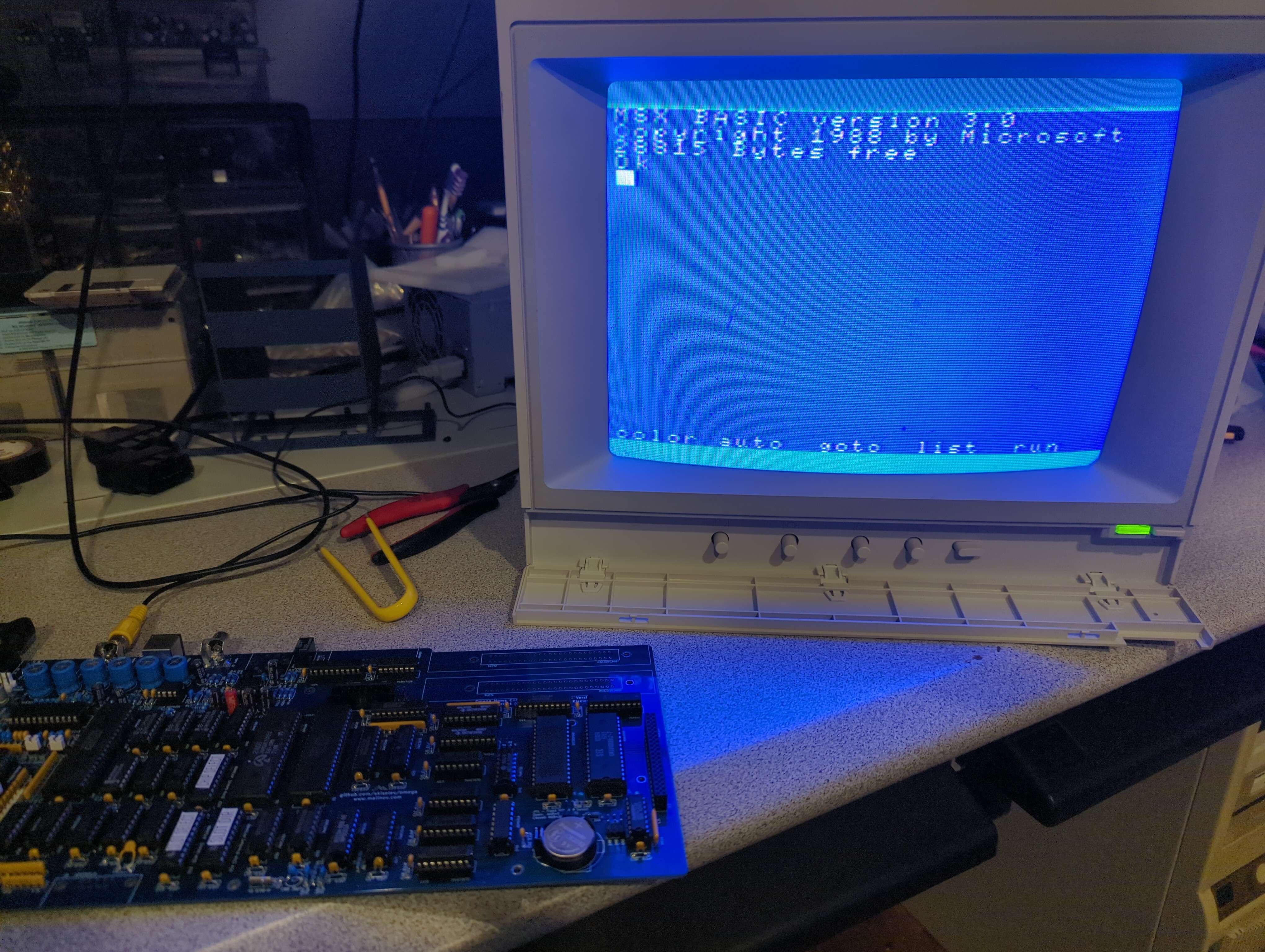
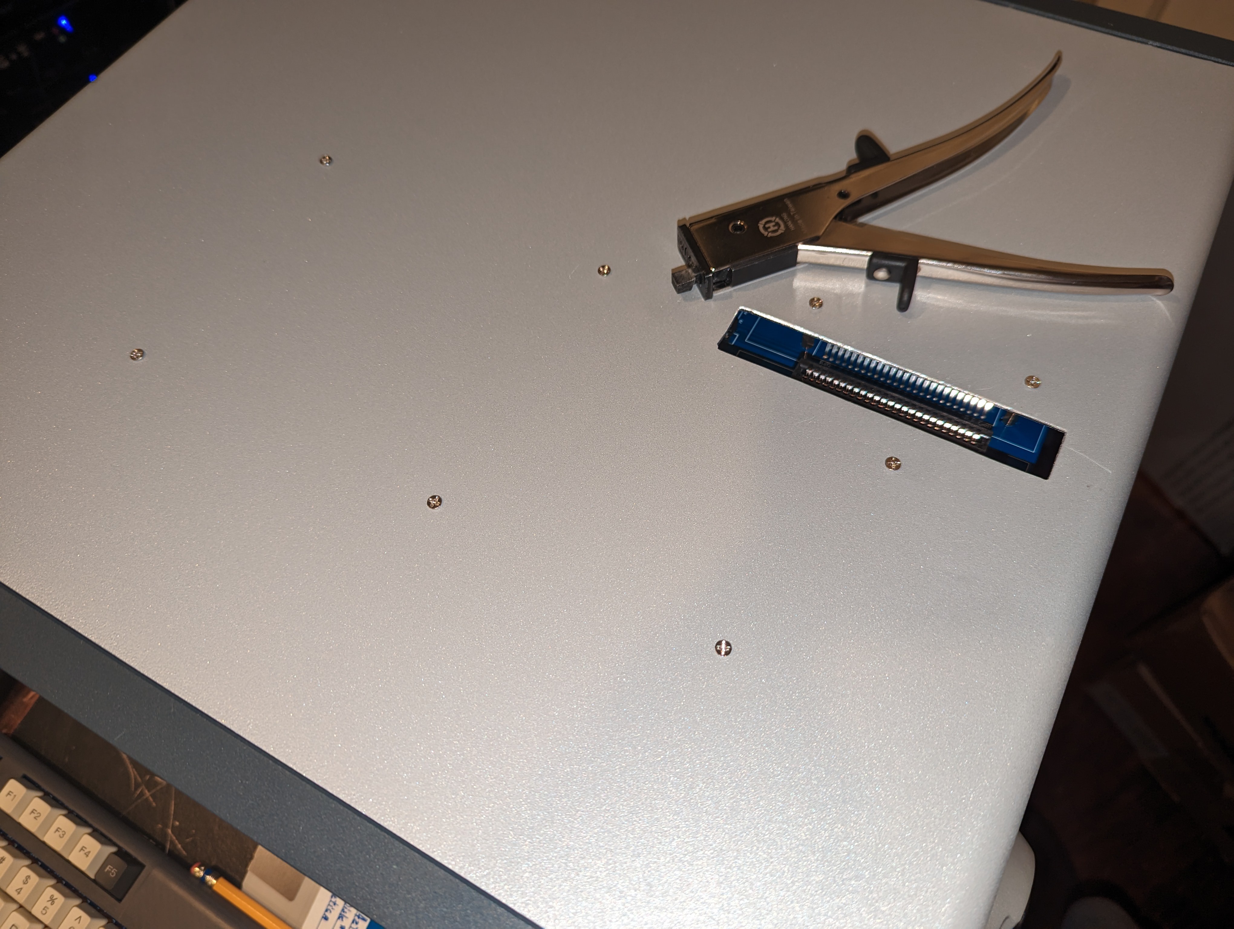
Building up the Omega went pretty easily. I began putting it through it's paces testing video and sound. Even manged to test the cassette port - loading/saving BASIC scripts. Also tested loading games from the computer from a generated WAV file. No real surprises until I tested loading a cartridge. The boot order is supposed to load from cartridge first but kept just booting into MSX-BASIC. I knew something must be wrong with the cartridge slots or GAL logic chips. While working on other aspects of the project I kept coming back to this problem for weeks. Voltages were correct, I used a logic analyzer to verify the slot select stuff was all working. Finally I decided to go back to the basics and check every single line of the 50-pin cartridge slots. Clock signals were good, all 16 address lines were good. Then I checked the data lines and noticed 2 were staying at logic LOWs while all the other data lines were moving. Using a continuity test on my meter, I found these 2 pins were indeed not connected. I followed the traces and, at least visually, they appeared perfect... but I knew it must somehow be broken traces. So I soldered in a couple of bodge wires and to my shock and amazement the thing booted my cartridge. Not sure what could have caused the broken traces, maybe I flexed the PCB at some point.. I'm just glad it's working and I haven't noticed anything flaky since.
 |  |
I carried out the S-Video mod to the Sony TV and that also worked perfectly. The difference between Composite & S-Video were pretty apparent. Colors looked better and more importantly it removed all of the composite artifacts.
 |  |
As I played around with how I'd mount everything inside the enclosure, it became obvious I wouldn't be able to mount the motherboard in such a way that I could get at all the IO ports easily. I decided that I would have to design a custom PCB which brought all the ports neatly to the front of the computer, where they're most easily accessed on a luggable computer. For power, I had a few spare ATX power supplies so I designed the board the take the 20-pin power header from the power supply. Turning the power on is just a matter of shorting 2 pins, so I used a toggle switch. It was pretty difficult to find a right-angle toggle switch but ultimately this one worked well.
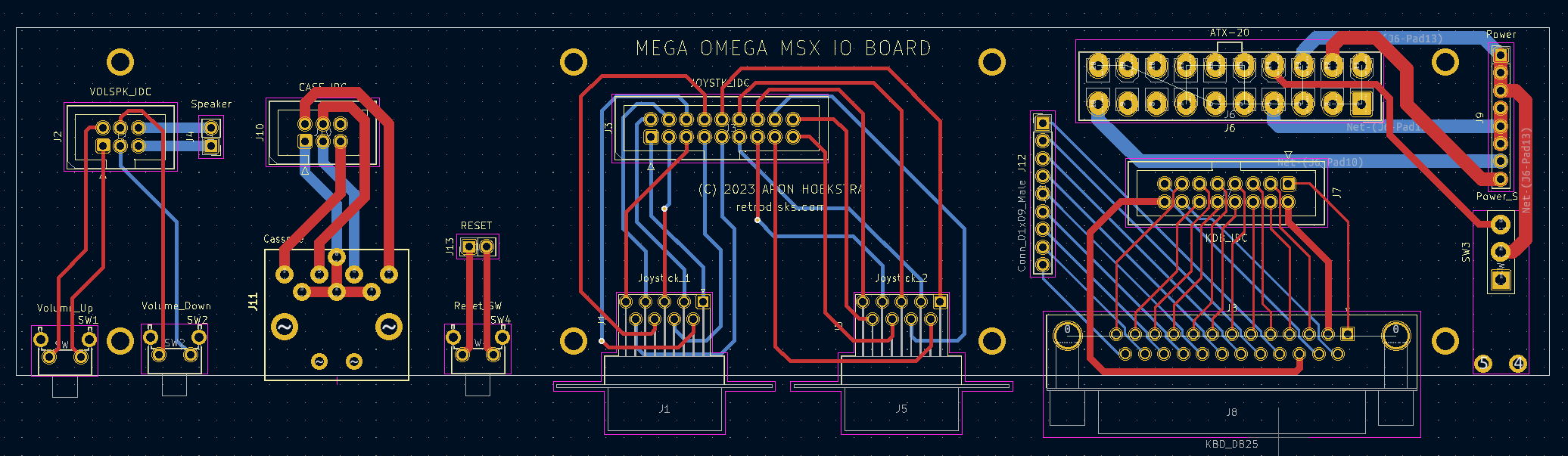
Here is what I ended up with (partially populated in this photo).
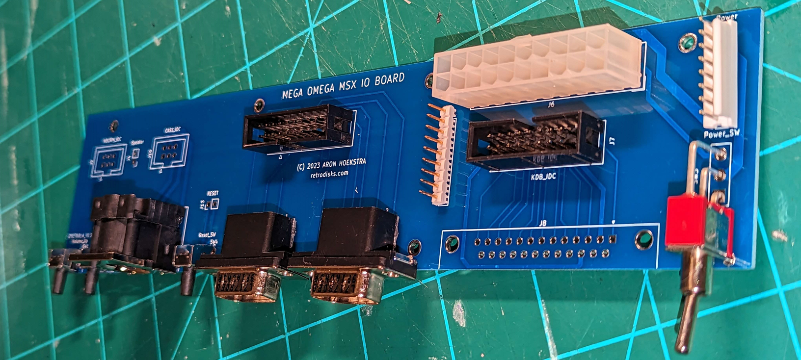
This takes the power from the PSU and adds a switch. It routes the necessary power lines back out to the Omega using an 8-pin header (GND, 5V, +12V, -12V). It breaks out the keyboard input to a DB-25 connector. Brings the 2 DE-9 joystick conncetors out to the front, as well as the Cassette port. There's a RESET switch which is just a simple toggle switch. And finally there's a header which takes the speaker output from the TV, as well as a volume up/down buttons which route back to the TV logic board.
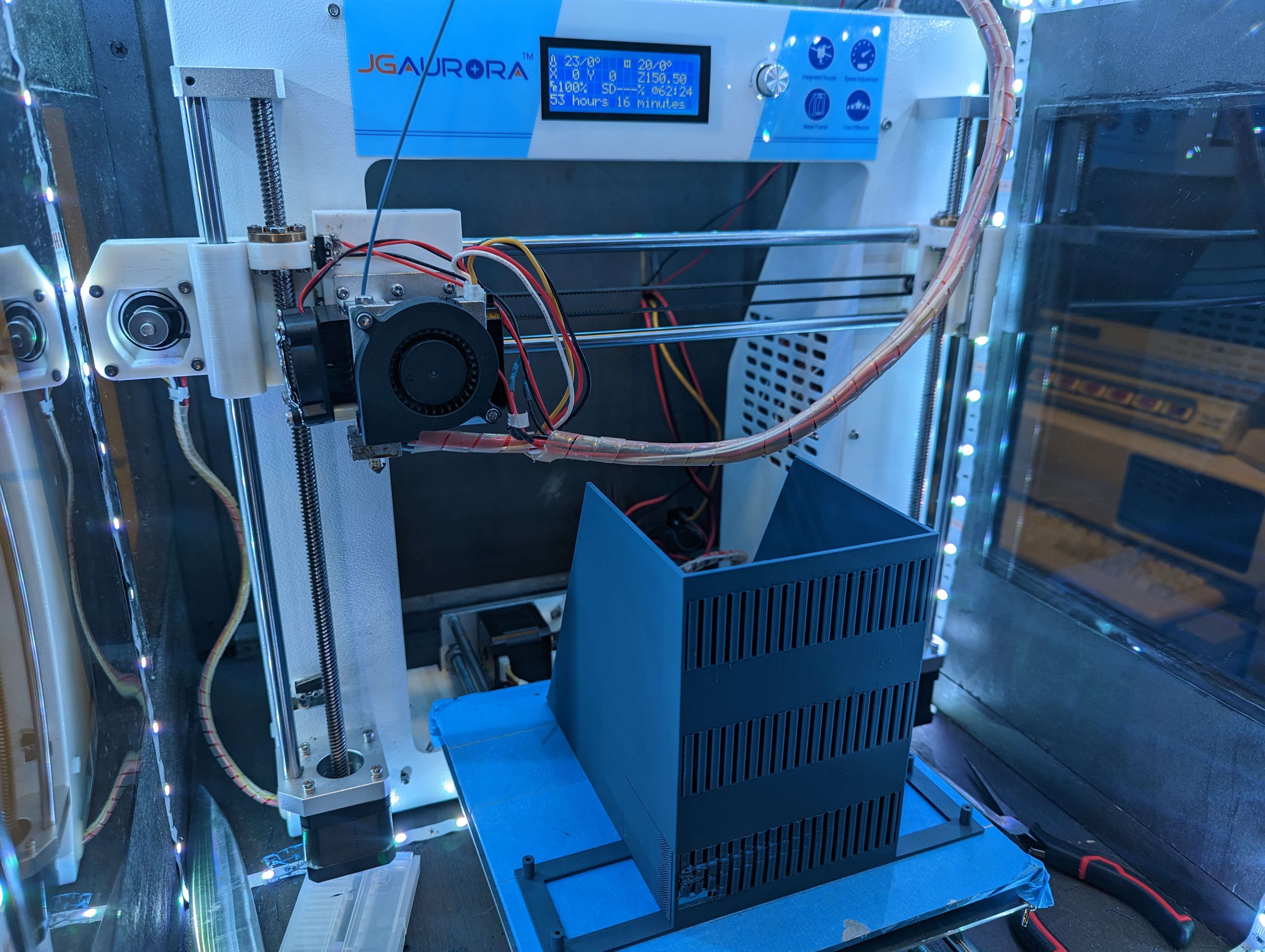
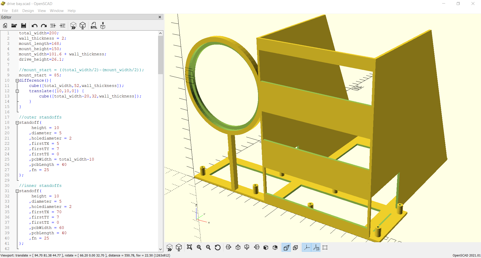
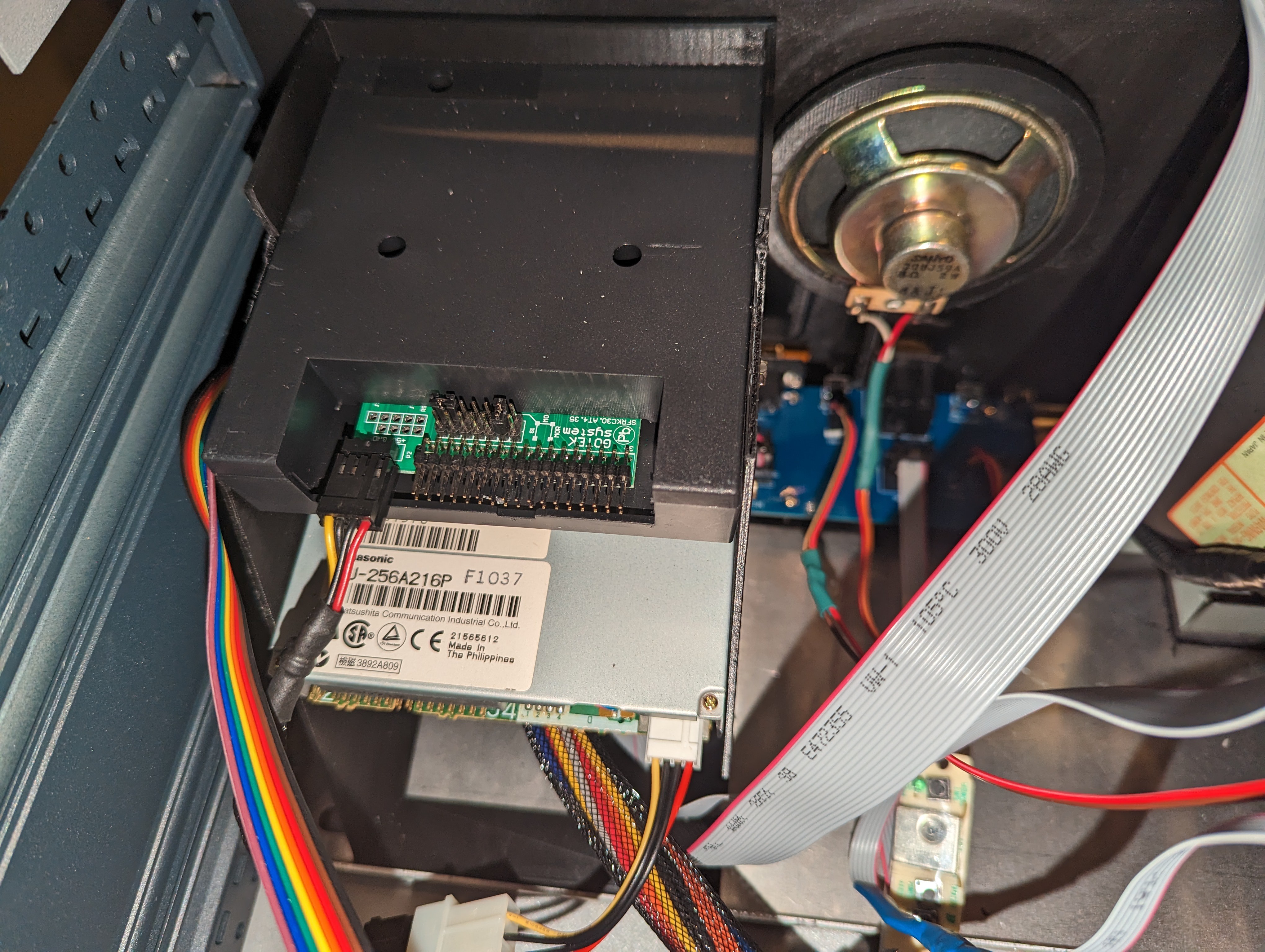
Now I needed a way to mount the PCB towards the front of the enclosure, but also needed to figure how I'd mount the speaker facing towards the front and the 2 floppy drives. It took to my favorite CAD software, OpenSCAD and after a few revisions, ended up with this.
An earlier revision of the pcb mount/drive bay on my 3D printer
OpenSCAD rendering of my final revision
Next, I turned my attention to the front panel. While the enclosure came with integrated sides, top and bottom pieces, it did not come with a front or rear panel. I decided to go with a piece of black/opaque acrylic because I knew it would be easy enough to cut and work with. I ordered from this eBay seller. I measured the size I needed and ordered the next size up. I contacted the seller, and they agreed to cut it to my specifications. When they arrived they fit perfectly - but now it was up to me to open up some holes for the ports. At first I thought I'd try to just drill and cut the holes by hand but thought that would probably end up looking like crap, so was at a crossroads..
What to do.. what to do....
I know! let's learn (yet another) new hobby!
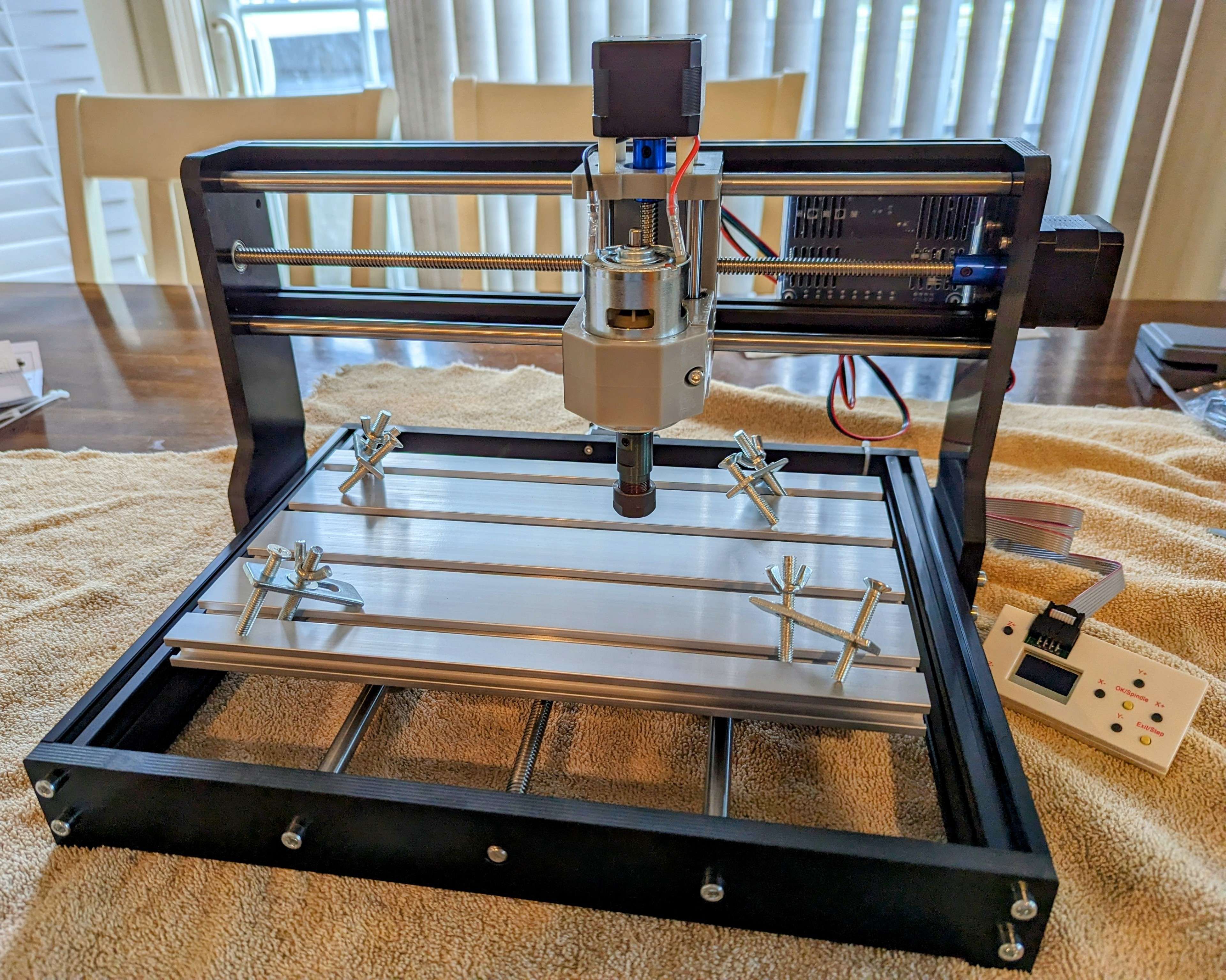
I had always wanted to try a CNC machine and this was the perfect excuse opportunity to buy one and give it a whirl. So after a couple weeks of research I bought a Genmitsu CNC 3018-PRO. Here it is fully assembled:
Having a pretty good understanding of 3D printing, I thought CNC would be a breeze. While my previous knowledge may have been helpful, one thing was clear: I didn't know what I didn't know. I didn't know what format the machine wanted cutouts in or how to make them. However, after several days of following tutorials I finally nailed down a procedure.
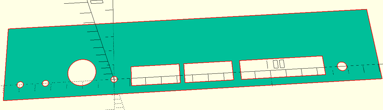
- Design cutout using OpenSCAD - basically create a cube and cut away shapes.
- Export the drawing to an STL.
- Use another OpenSCAD function to import the STL and "project" the 3D object as a flat 2D object. Export to a DXF.
- Use "DXF2GCODE" to create a cutting route. Import the DXF, drop Layer 1 (the cube perimeter). Set the right drill settings (depth, etc), export to GCode.
- Use "Universal Gcode Sender" to control the CNC machine. Figure out some way to clamp the piece. Set the origin, cross your fingers and hit Send.
Due to the size of the piece of acrylic, I had to break the cuts into multiple parts. I did the bottom ports, floppy drive openings, speaker grill, and finally the CRT cutout.
After a few test cuts on wood, I was ready to try it on the acrylic. Since I didn't have any extra acrylic I really only had one shot at this.. In the end I think it turned out pretty good. Not perfect but whatever - good enough to move on.
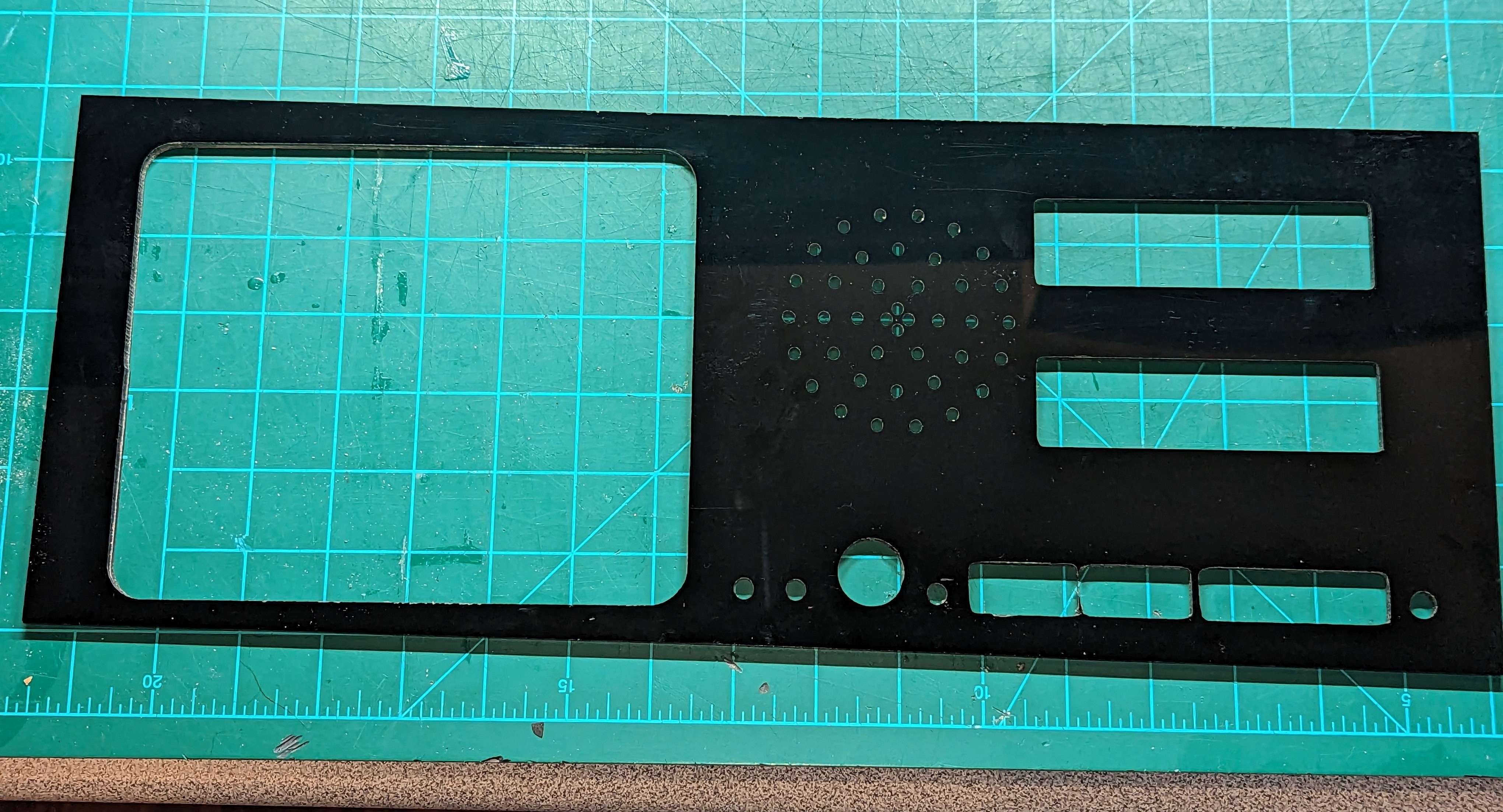
One last thing is I decided I didn't like was the glossy finish. Way too prone to attracting fingerprints and too reflective. So I used a leftover can of "hammered" black spray paint which gave it a nice texture and more of a matte finish.
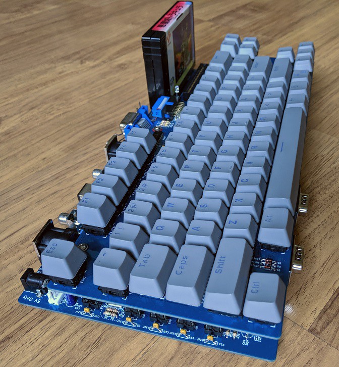
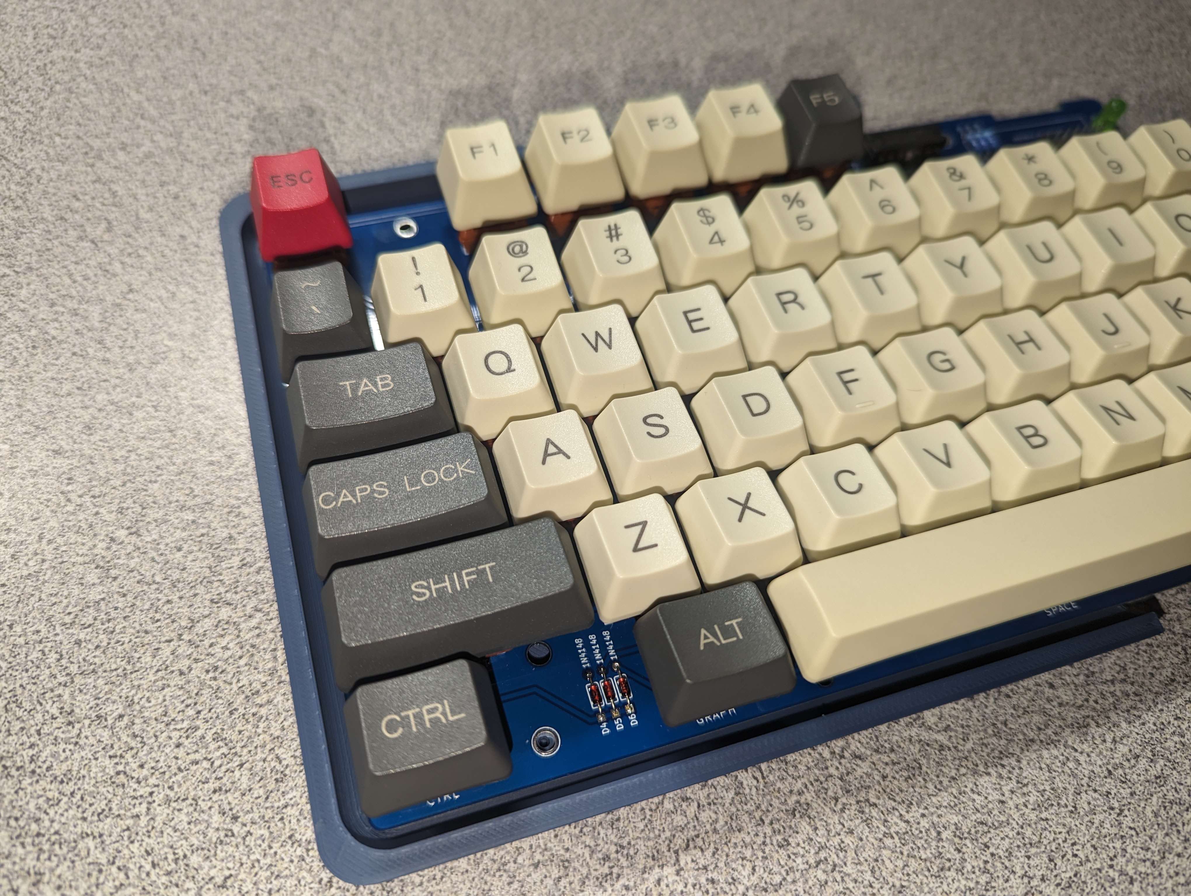
Now I had to tackle the keyboard. It was designed specifically for the Omega, and is on it's own separate PCB. It's meant to be stacked on top of the motherboard. One thing that became quickly apparent early on was that it would look dinky next to this massive enclosure - so I would have to add something that it's lacking.. a numeric keypad. If I did that, it would at least look like a full sized keyboard.. First step was to design a PCB. I added the DB25 connector to bring the keyboard signals back to my IO board. I used the Omega Keyboard as a reference and pulled components out from there as a library to design my own board. Thankfully Omega was designed in KiCAD, the PCB design software I'm already most familiar with.
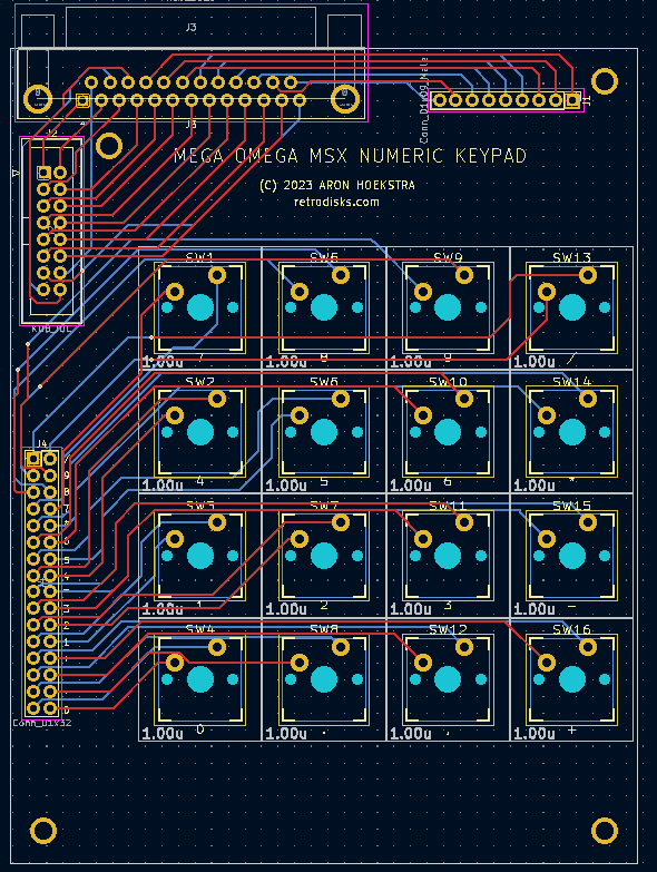 | 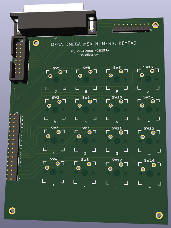 |
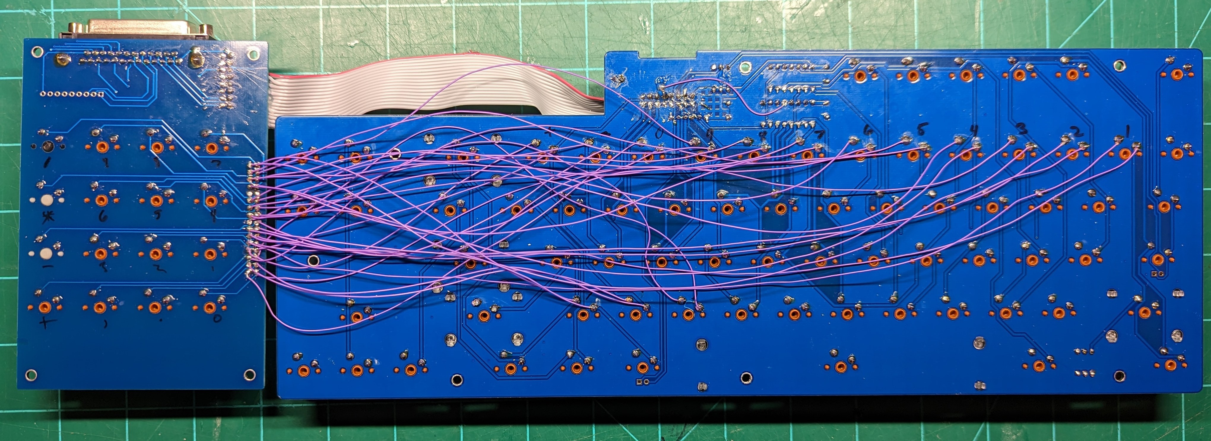
Now don't get me wrong, this board is a total hack and involves wiring up the keys to the main part of the keyboard. It is not a true MSX implementation of a keypad - that would take work to send more data from the keyboard matrix to the Omega than it currently supports. But... it works and most importantly it makes the keyboard look full-sized. This part was mostly about aesthetics..
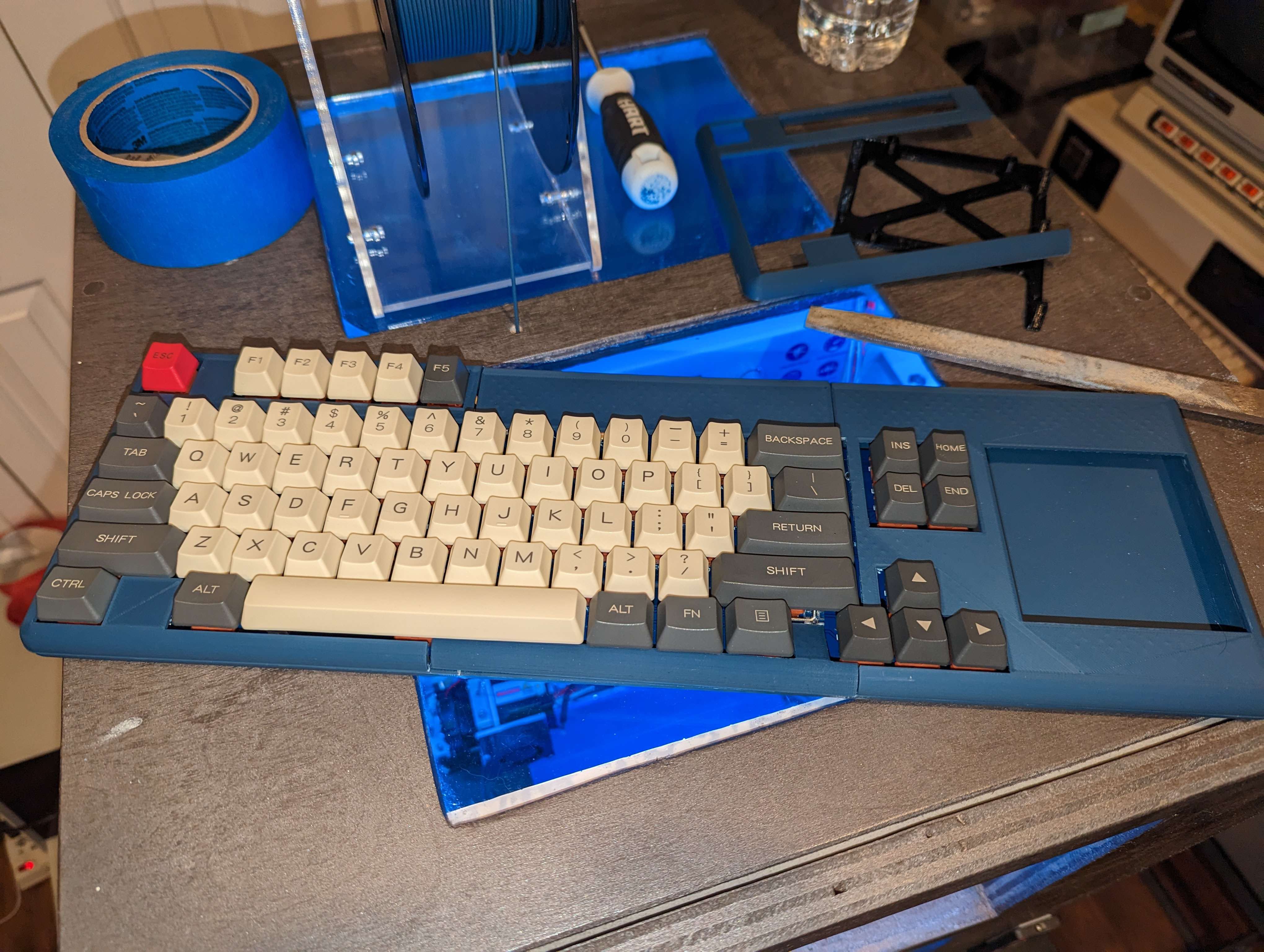
Now that I had the PCB designed, I needed a keyboard case. OpenSCAD to the rescue...again. This took quite a while and was a bit frustrating to get all the measurements right.
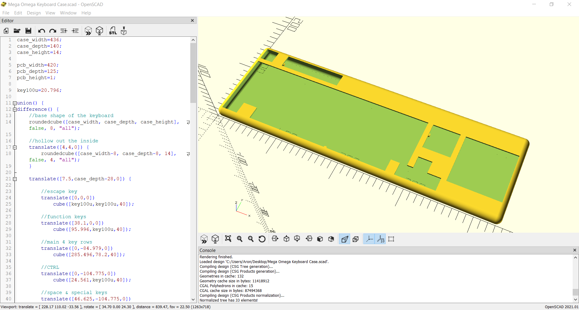
Also due to the size it would need to be "split" and 3D printed in parts, then glued together. To fit on my print bed, I split it into 6 equal parts.
First piece off the printer
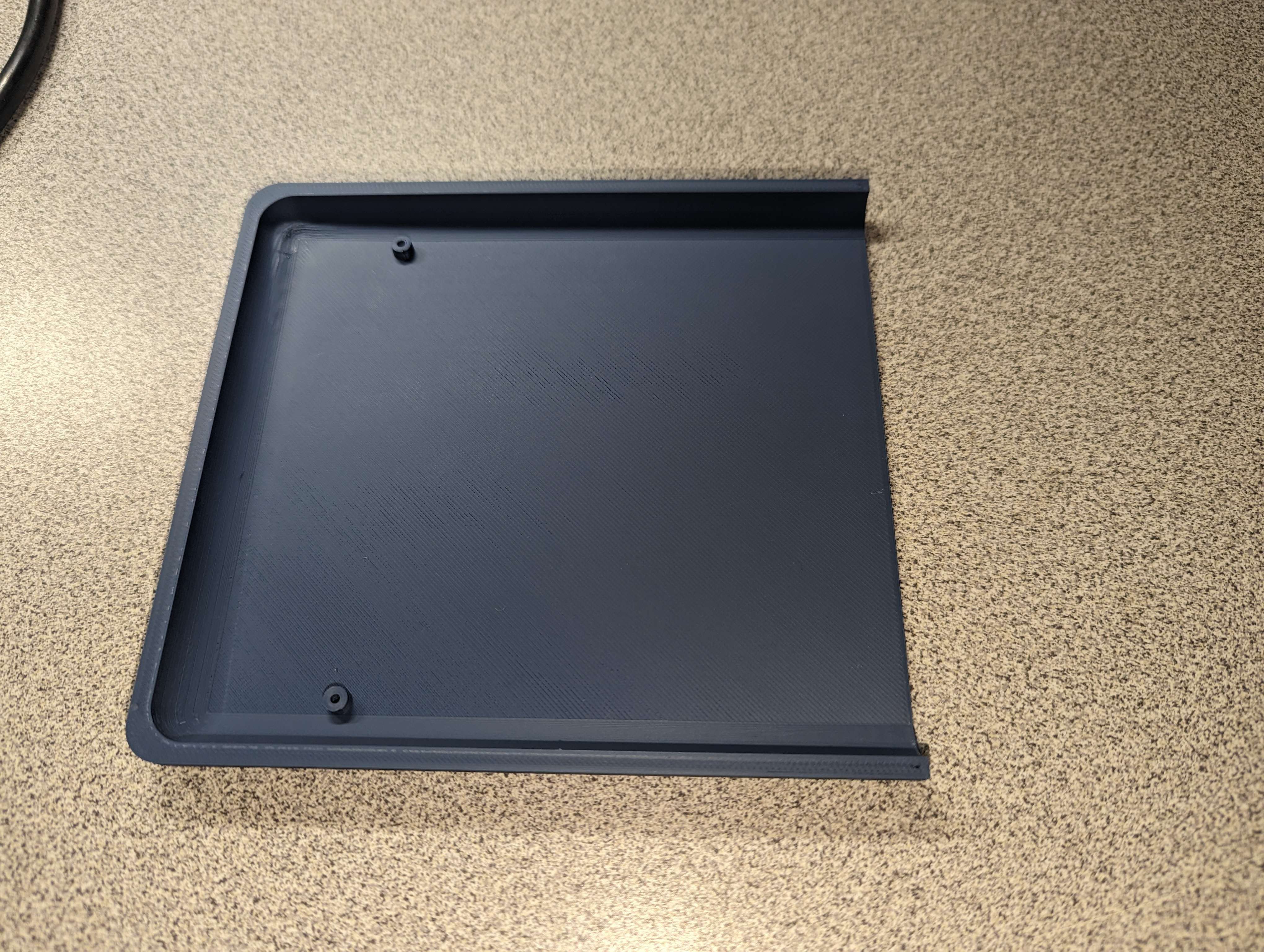 | Checking the standoffs alignment..
 |
Making sure it all lines up..
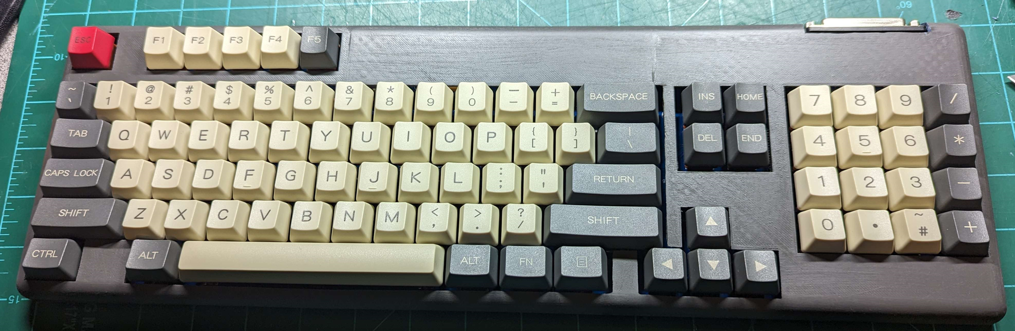
After gluing the parts together, I sanded and painted the whole case. I think it turned out pretty well. Could use some more sanding ... but good enough for now.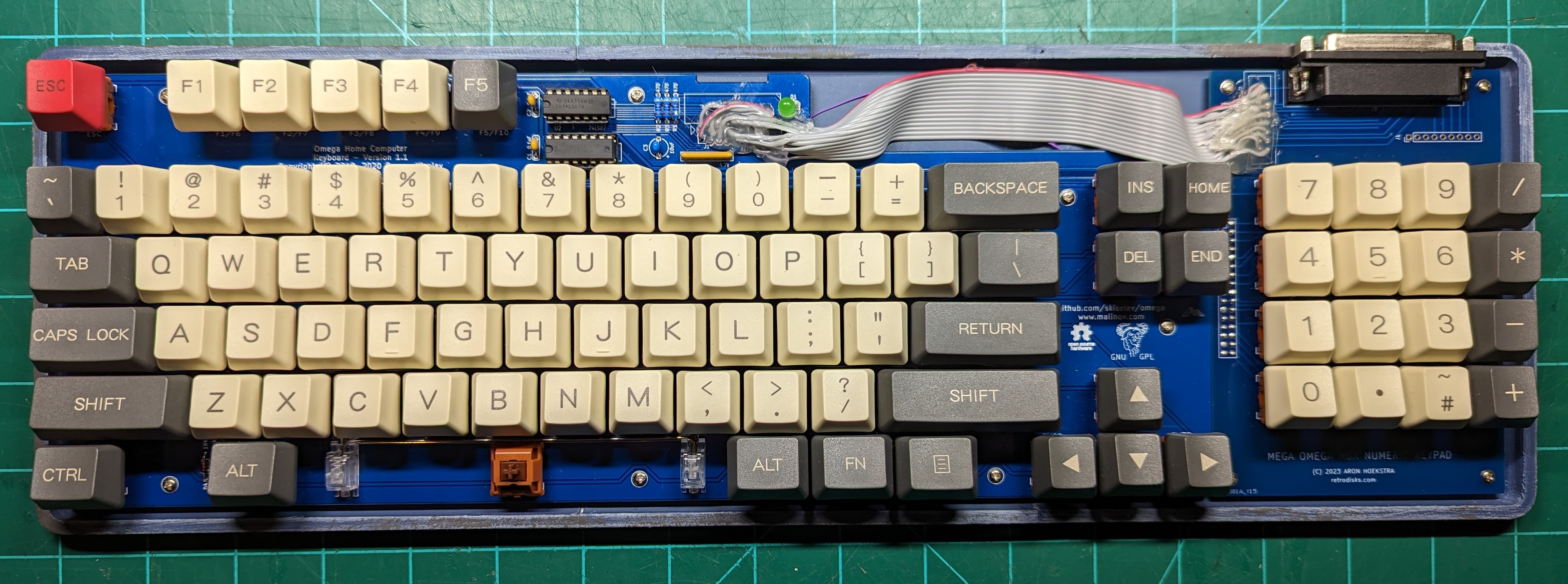
Putting it all together
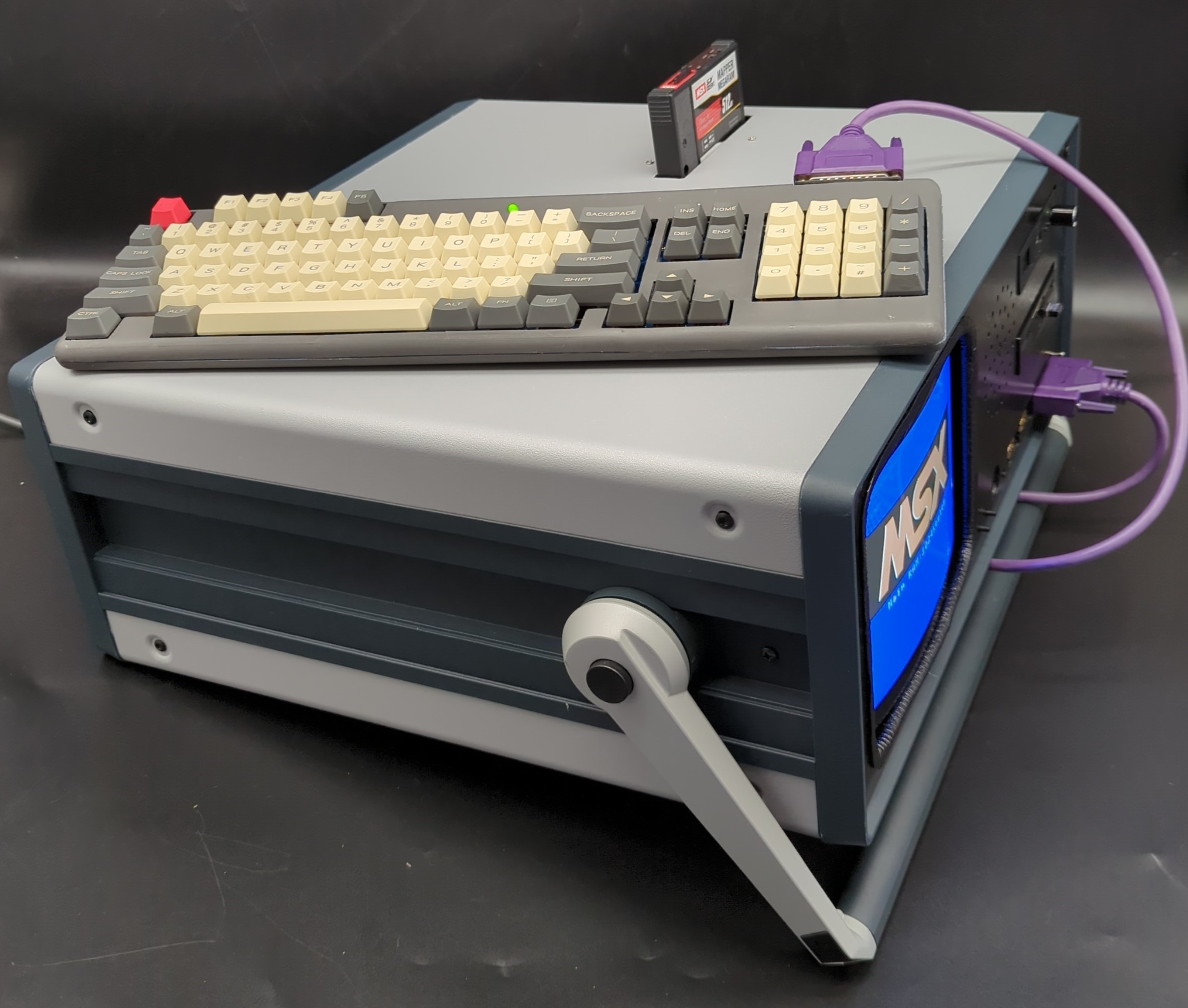
I knew mounting everything would be a challenge for me, it's just not one of my strong suits. After a lot of trial & error I did manage to get everything securely mounted inside the case.
The CRT came completely out of the plastic case it came in. I mounted it by re-configuring a metal bracket that it came with. I had to raise it up with some small standoffs to center it vertically with the front panel. The logic and analog boards are also mounted with some standoffs, attached direct to the bottom panel of the enclosure. Not ideal but I couldn't think of anything that would allow all the wires to reach where they needed to.
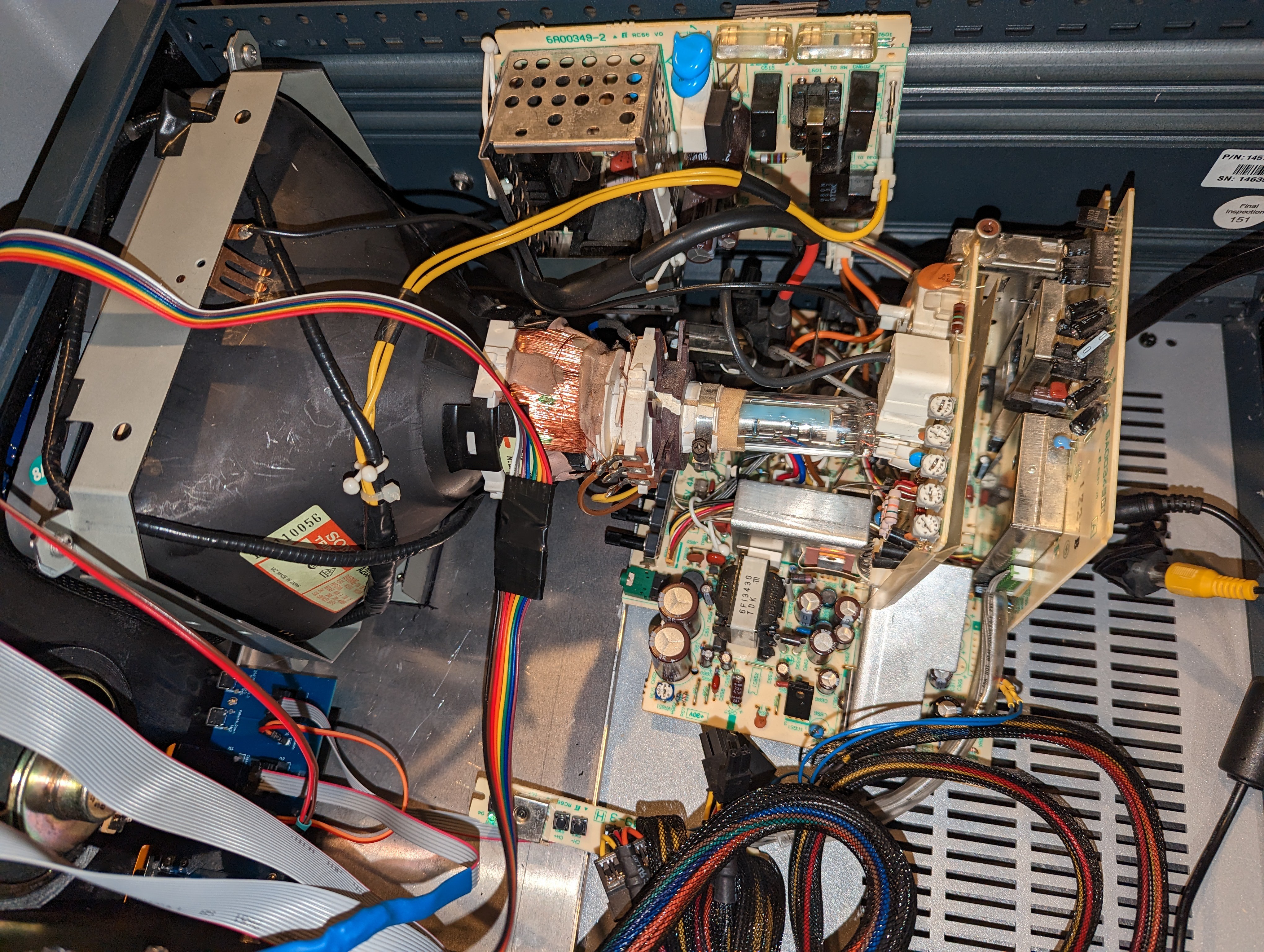
 |  |
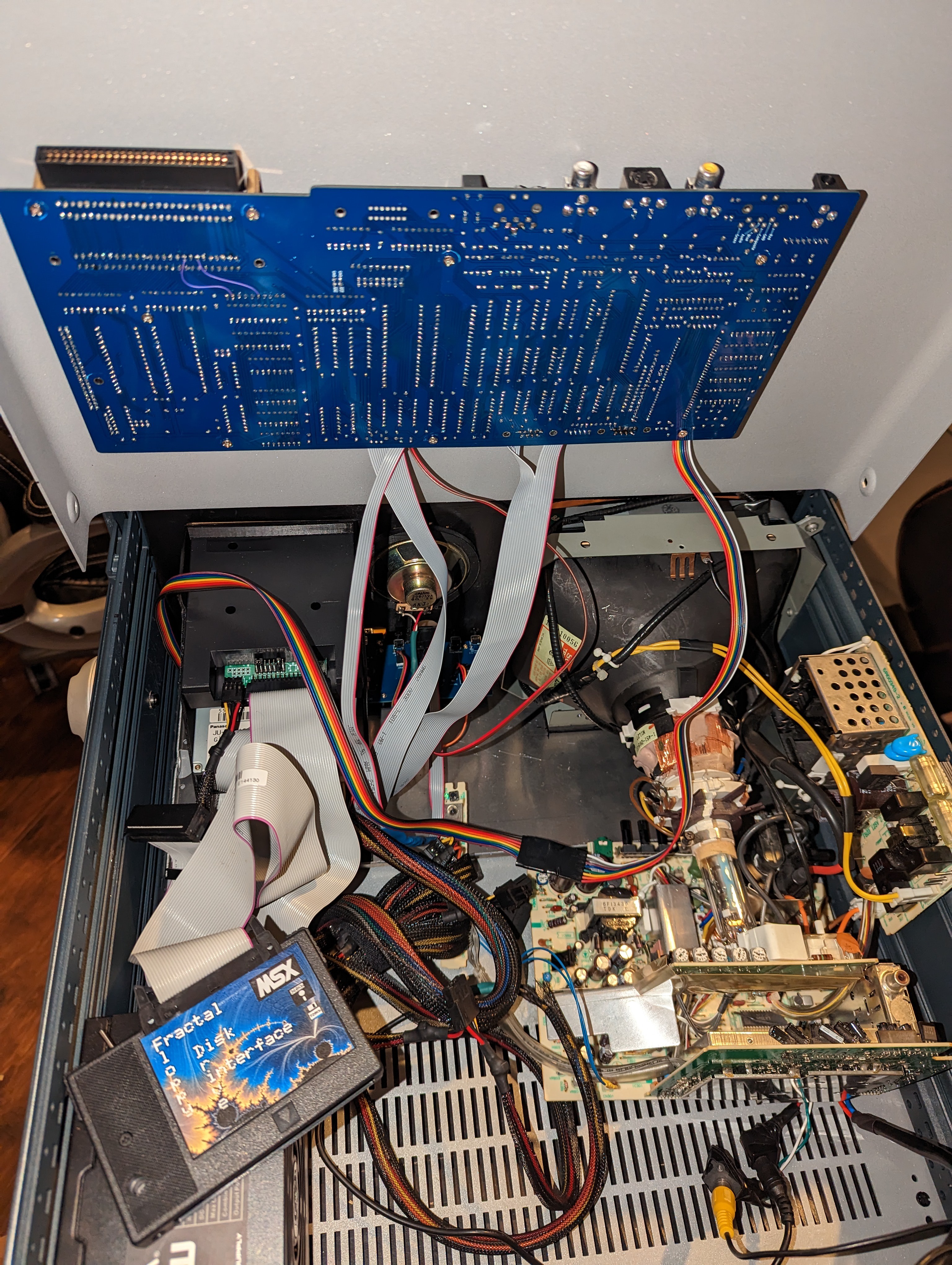
Yeah it looks a bit messy inside, maybe I'll work on cable management later. Probably not.
| Here's a video from when I first got the cassette port work. I was pretty excited. | And here's a video of the first actual software/game I got running over cassette. |
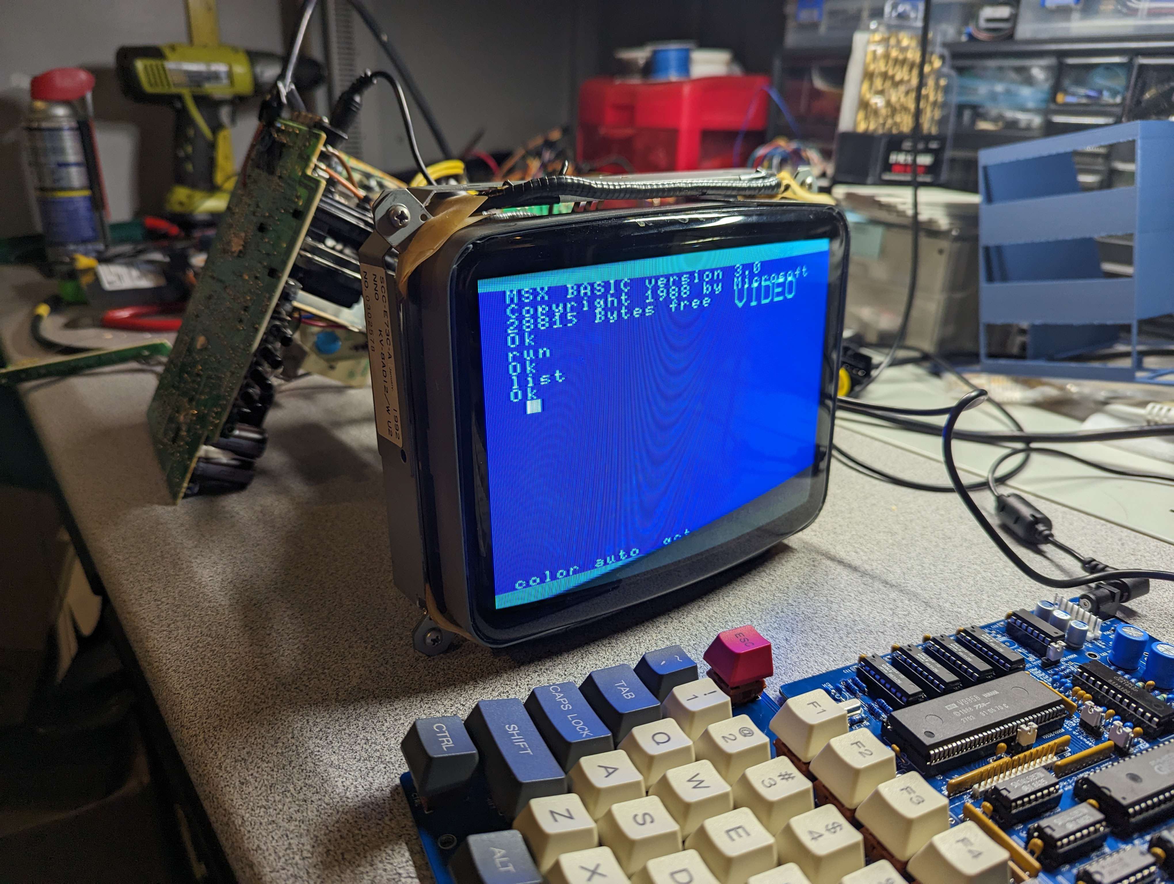
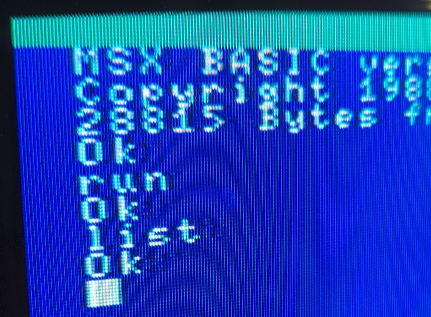
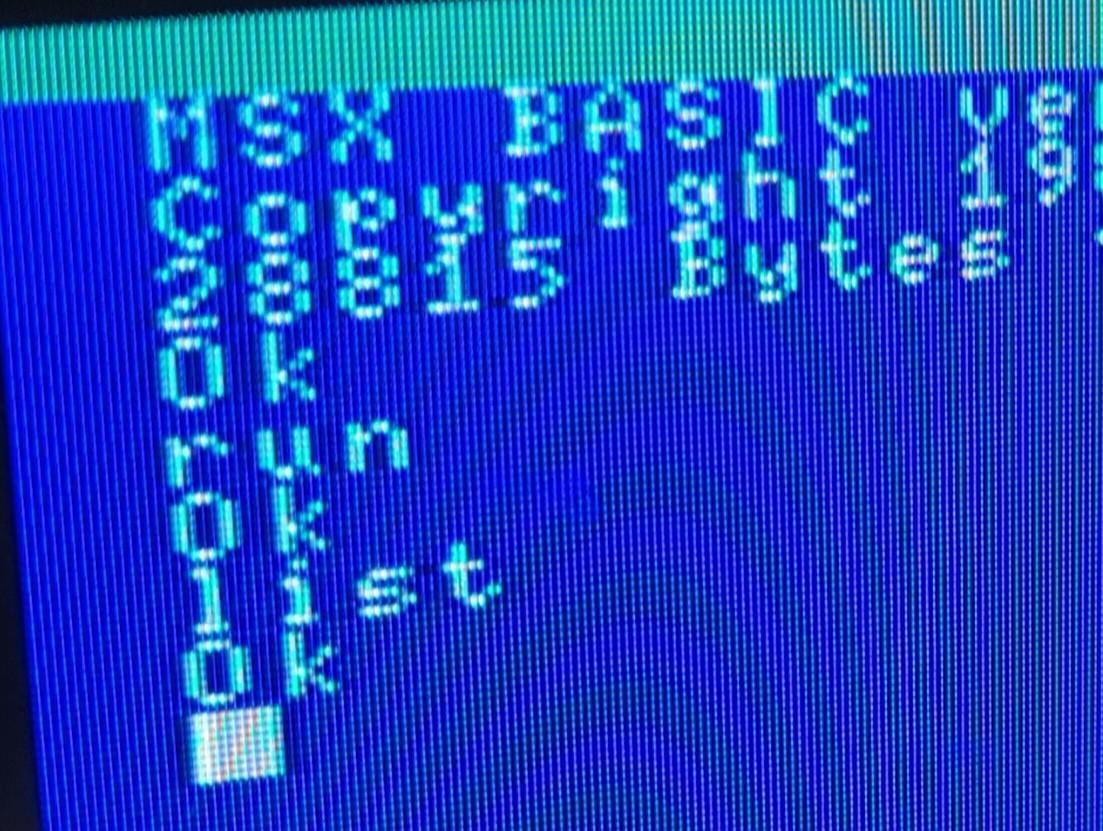
I eventually figured out how to get that annoying "VIDEO" message to go away but occasionally it comes back. If I just push the volume up or down, and wait a moment it clears itself. I'm really debating just disconnecting the OSD signal on the CRT's controller board.
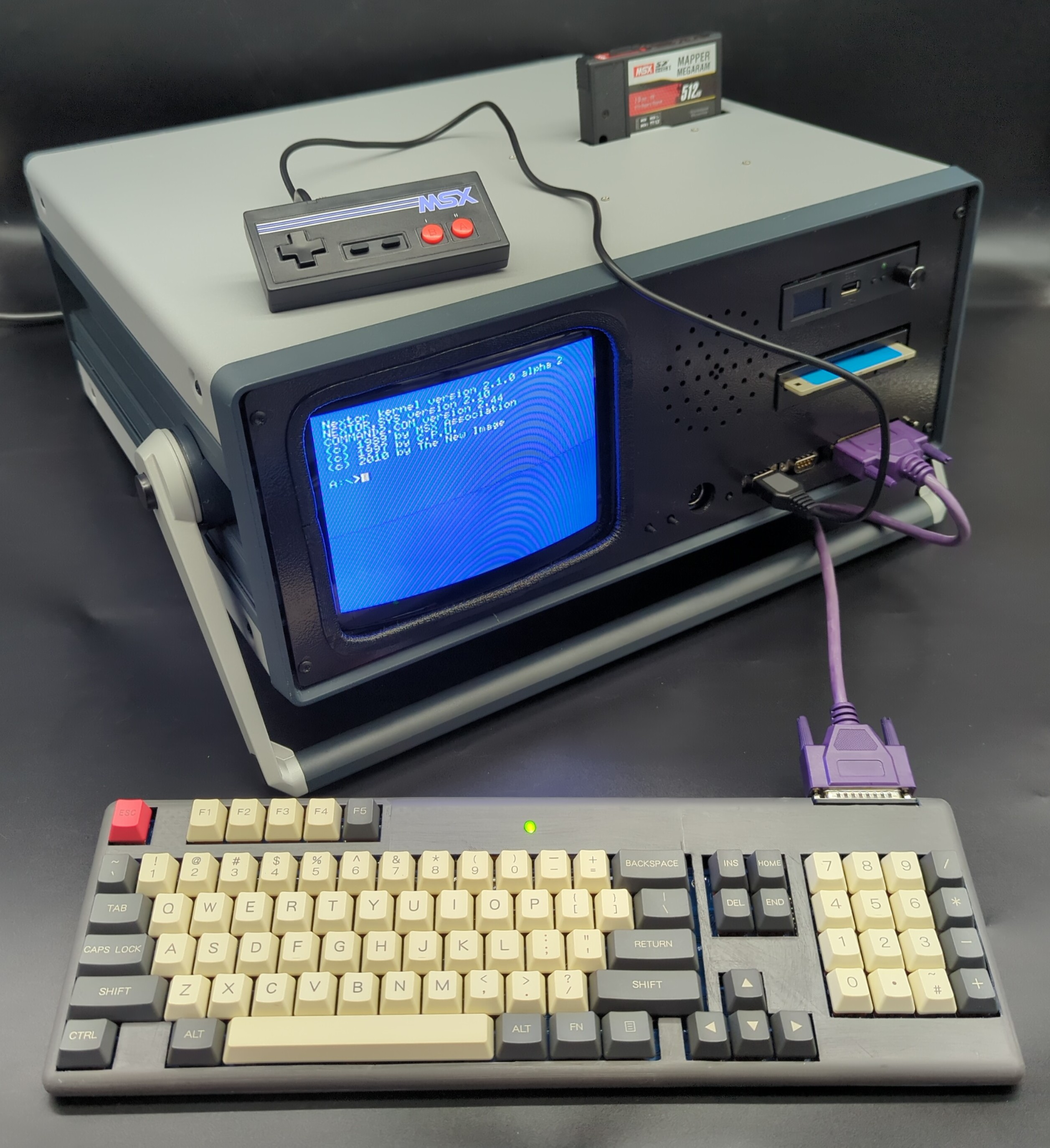
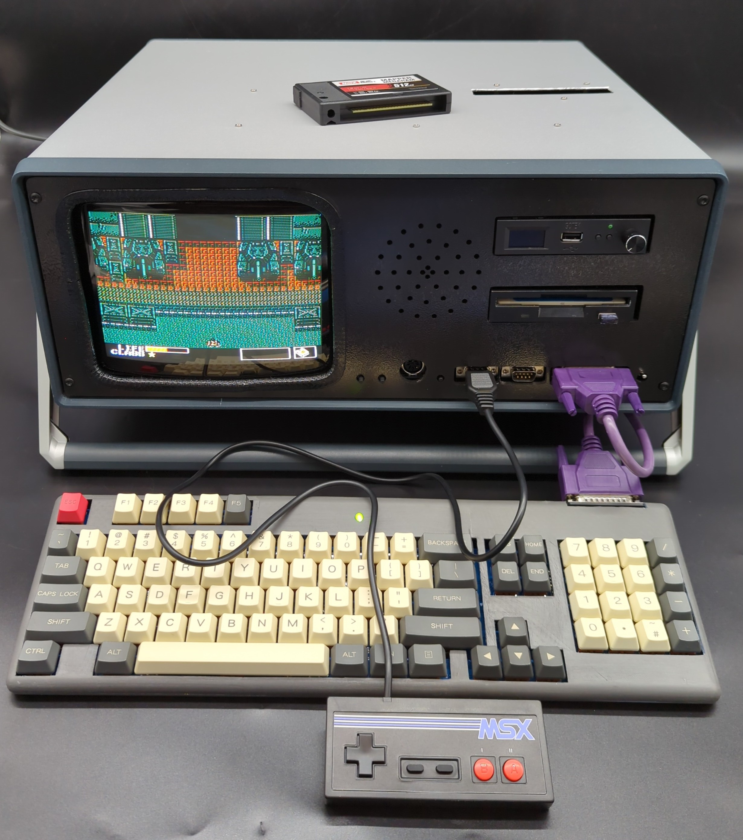
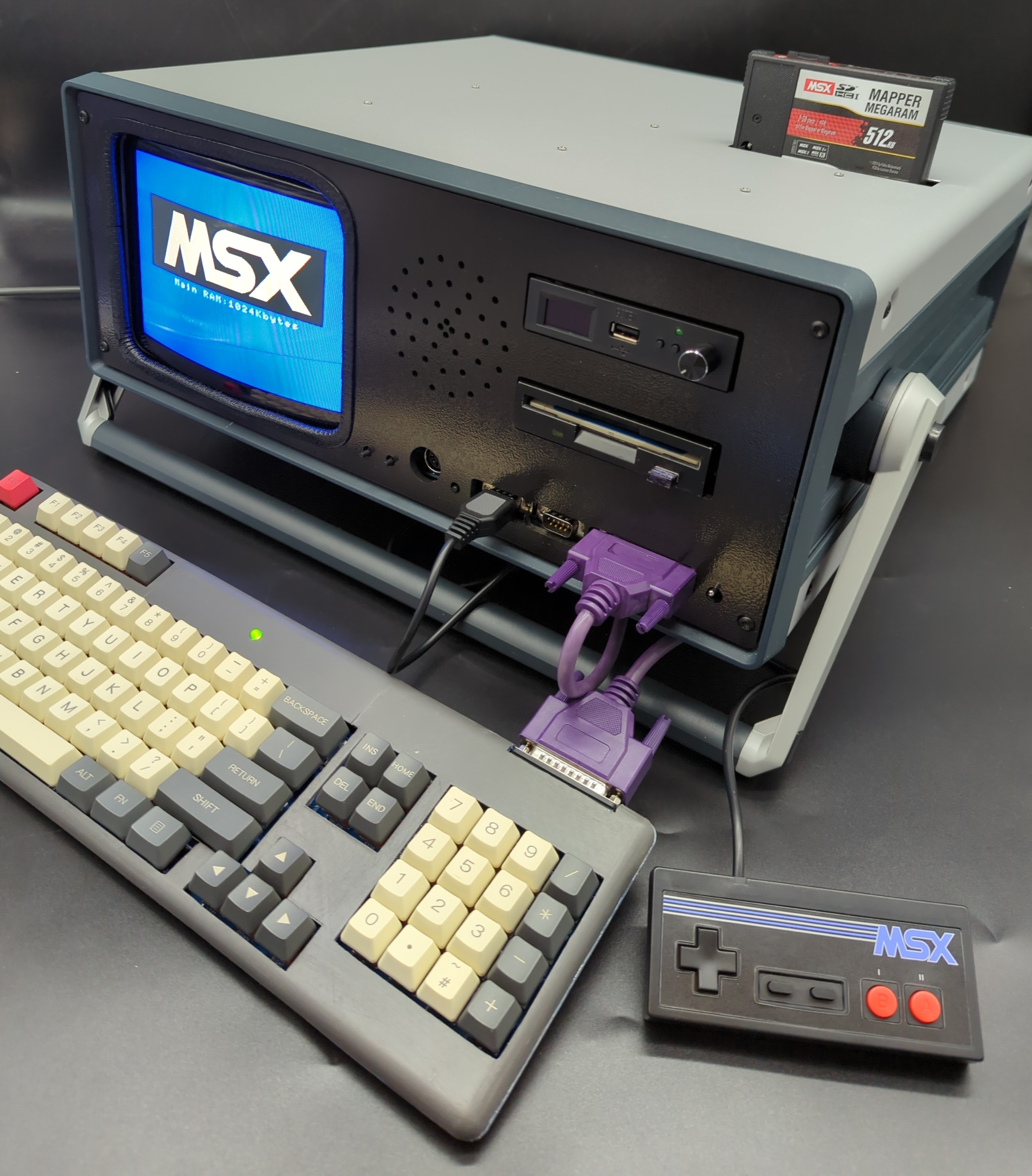
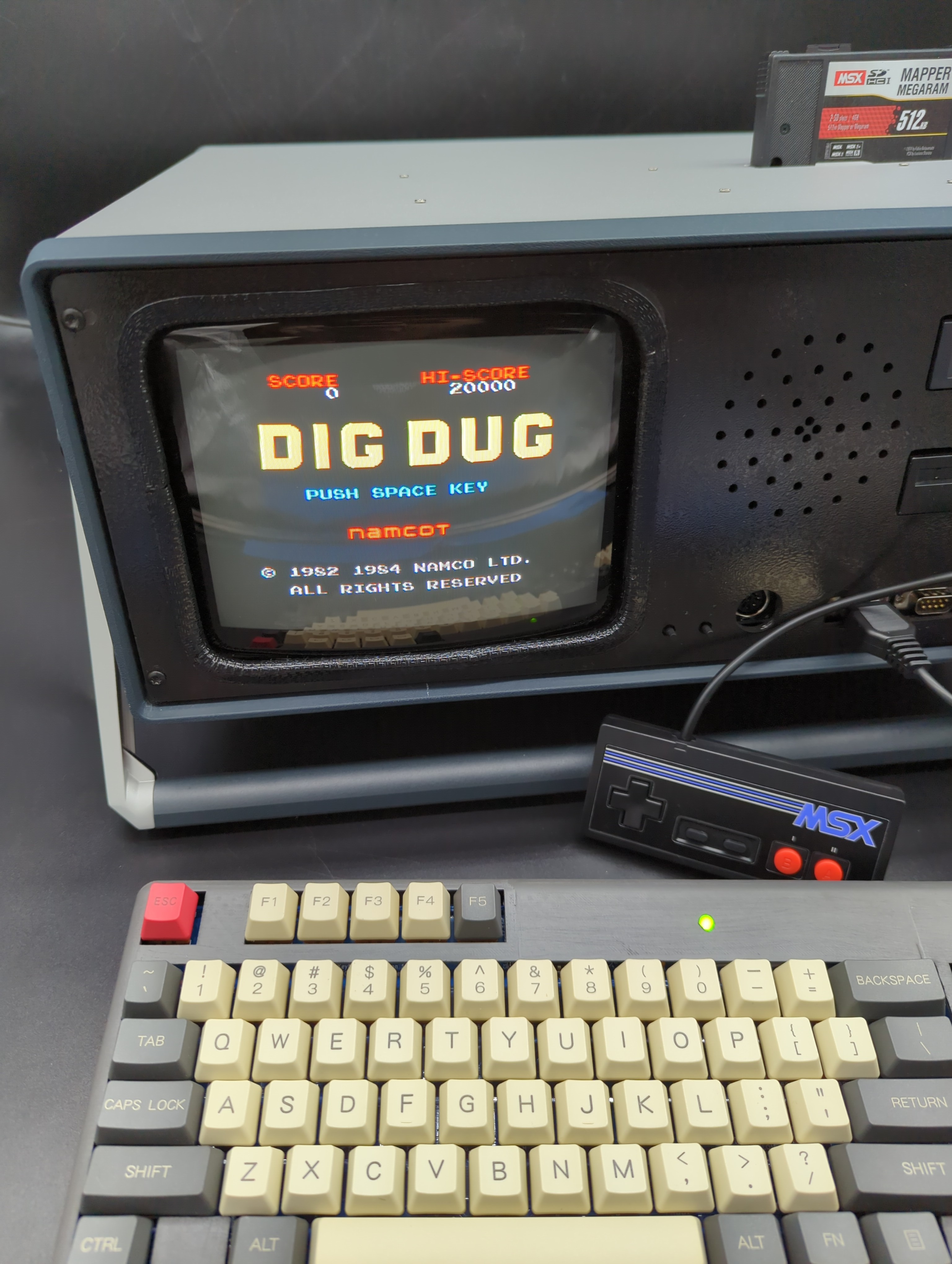
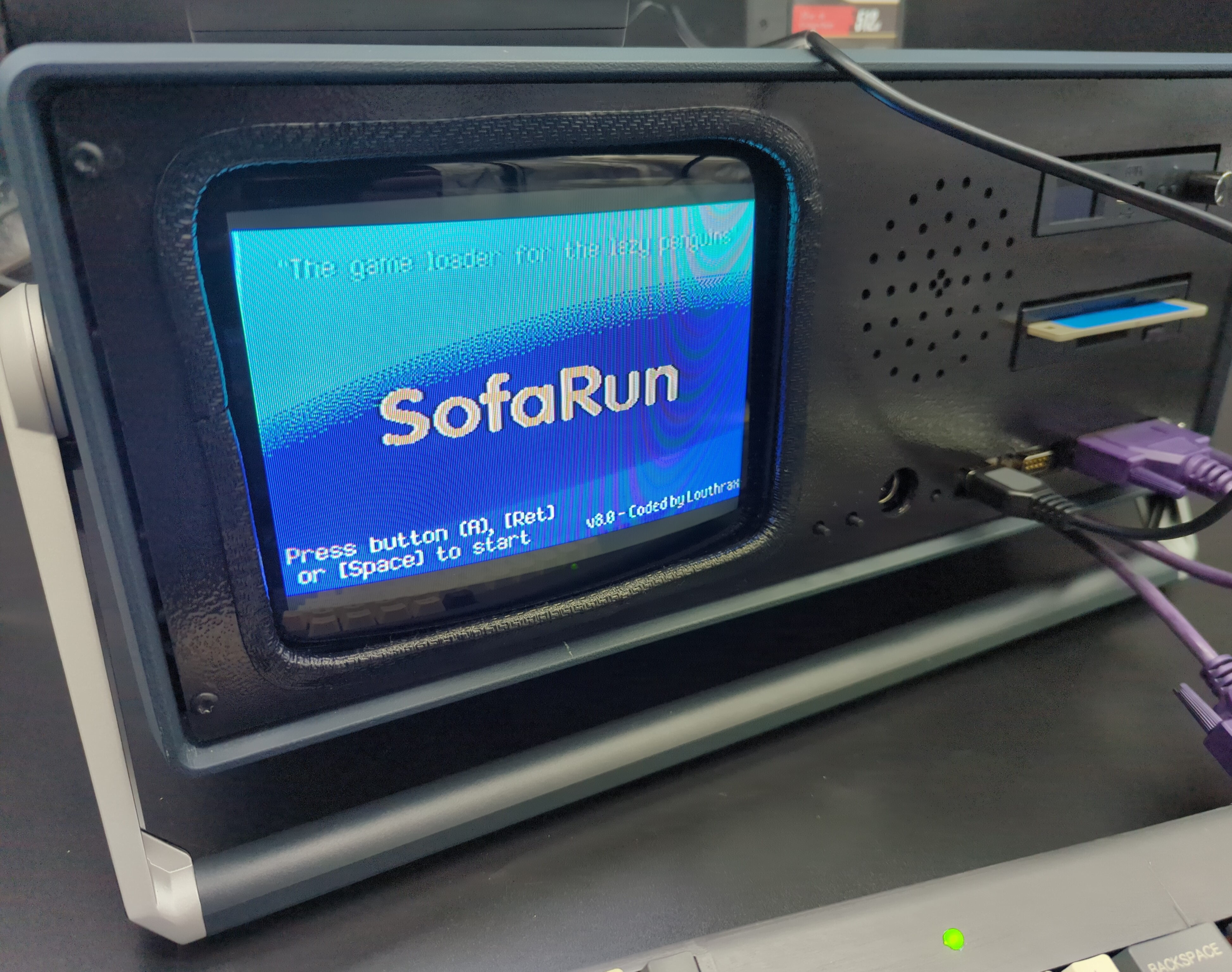
The only cartridge I have right now is this SD Mapper/MegaRAM - but it's enough for now. It comes loaded with tons of ROMS that can be loaded directly from the included SD card. The gamepad controller is brand new made by RetroGameBoyz - I wasn't sure what to expect when I ordered it, but wow am I impressed! They feel sturdy in your hand and most importantly, there is no play/mush in the buttons - they are tight and responsive. I ordered a 2nd!
So there you have it... For all the projects I tend to start and shelve, it feels nice to bring one all the way through to fruition.
I have shared all the files here for the PCBs, 3D print and CNC cuts in case anyone else was crazy enough to try to build something similar. I also have a few PCB spares too, so reach out if interested.
Here's one last video of me (poorly) playing Zanac: