 thpoll
The very first case for the left side was done manually. Just like I did for my macro pad prototype - measure everything and then model a fitting case:
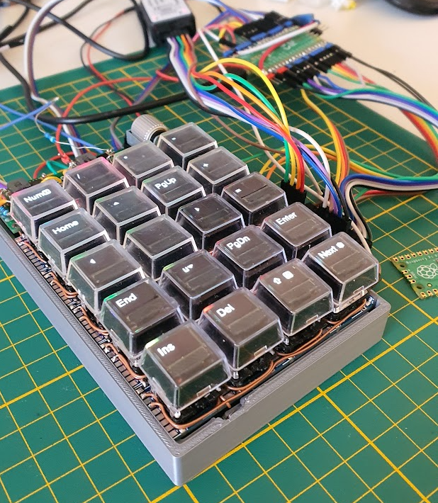
Well, still I had to break away some parts as you can see :-P, this process usually needs multiple iterations to really fit well.
For left side case, I had at least some automatic step, so I haven't had to measure everything: In KiCad, I exported an SVG from the PCB outline and started modelling a case around that:
That worked, but I don't want to repeat that for the right side as it is just too much manual work. Also any changes to the position of the LEDs, USB connector or the mounting holes would be a disaster!
The good part is, that I now know how the case should look like from the design standpoint!
What I also learned, is that there would be less manual modelling needed, if I placed all bottom SMD parts well within the PCB (well at least 2mm+). Then I don't need to modify the edge where the PCB sits on because of colliding parts. Obvious? Right? Seems like I had to experience that first to realize.
Next Iteration
So for the right side I wanted to start with a more generic and automated approach that ideally creates a fitting case based on the PCB alone.
To make the project as open as possible, I resisted to use any modelling software that would need a paid license. With these two ideas in mind I was wondering if I could use OpenSCAD to programmatically generate the case.
I already used OpenSCAD for the keycap stems and the display holder, why not for the case as well?
So How does it work now?
I still export the outline as SVG, however without all the cut-outs for key switches. In KiCad, you can select which layer to export and each layer can be a different SVG. So the most convenient thing is, to copy the board outline to a separate layer (since the key switch cutouts are also on that layer, but we don't need them). Then create a layer for each of the other physical features like:
1. Usb port cut-out (just a rectangle that can be extruded and subtracted)
2. LED cut-out for the status lights (just a line starting from the middle of the part perpendicular to the board outline)
3. Reset and Boot-Select switch cut-outs (again just rectangles)
4. And finally the stand-offs, which I just redraw as circles in a new layer as circles with the exact diameter of the drill hole.
So all together that makes 5 different SVGs (well, I also optionally had cut-outs for debug ports but that will not matter in the end).
All Set?
Unfortunately, my outline was not perfect (tiny gaps) and I had to fix it with InkScape to make one polygon out of it (I don't remember the exact steps, maybe there is some expert who can comment? Maybe there is a command line tool to do that?).
Apart from that, for some reason, all lines in my exported SVGs where in groups and I just got all lines out of any groups and deleted the empty groups as OpenSCAD had issues with objects in groups.
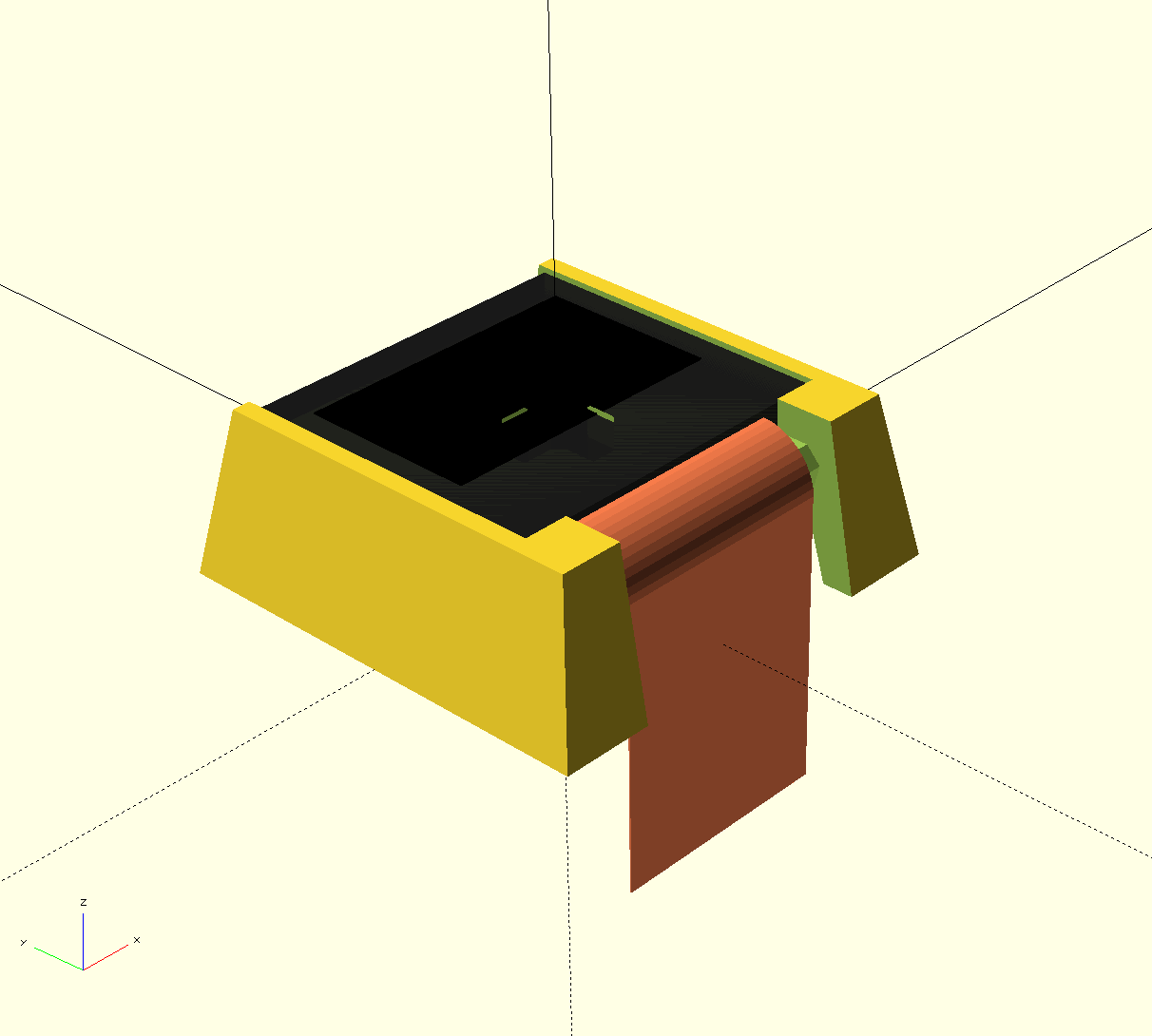
After these little cosmetic operations, I can load the generated SVGs into OpenSCAD:
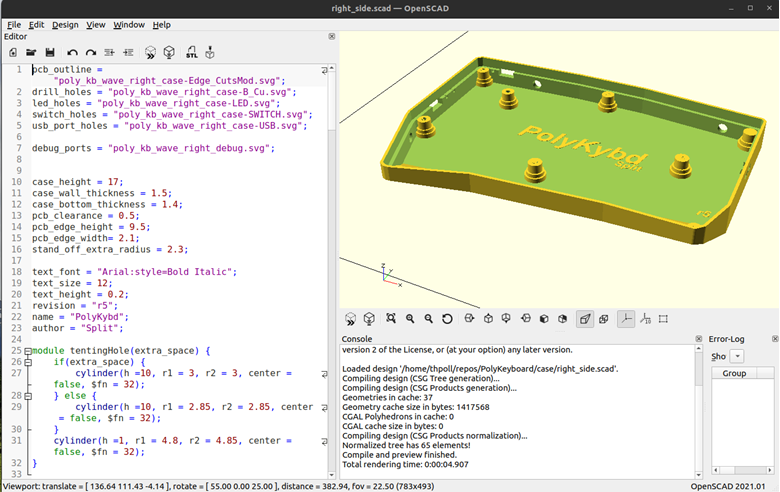
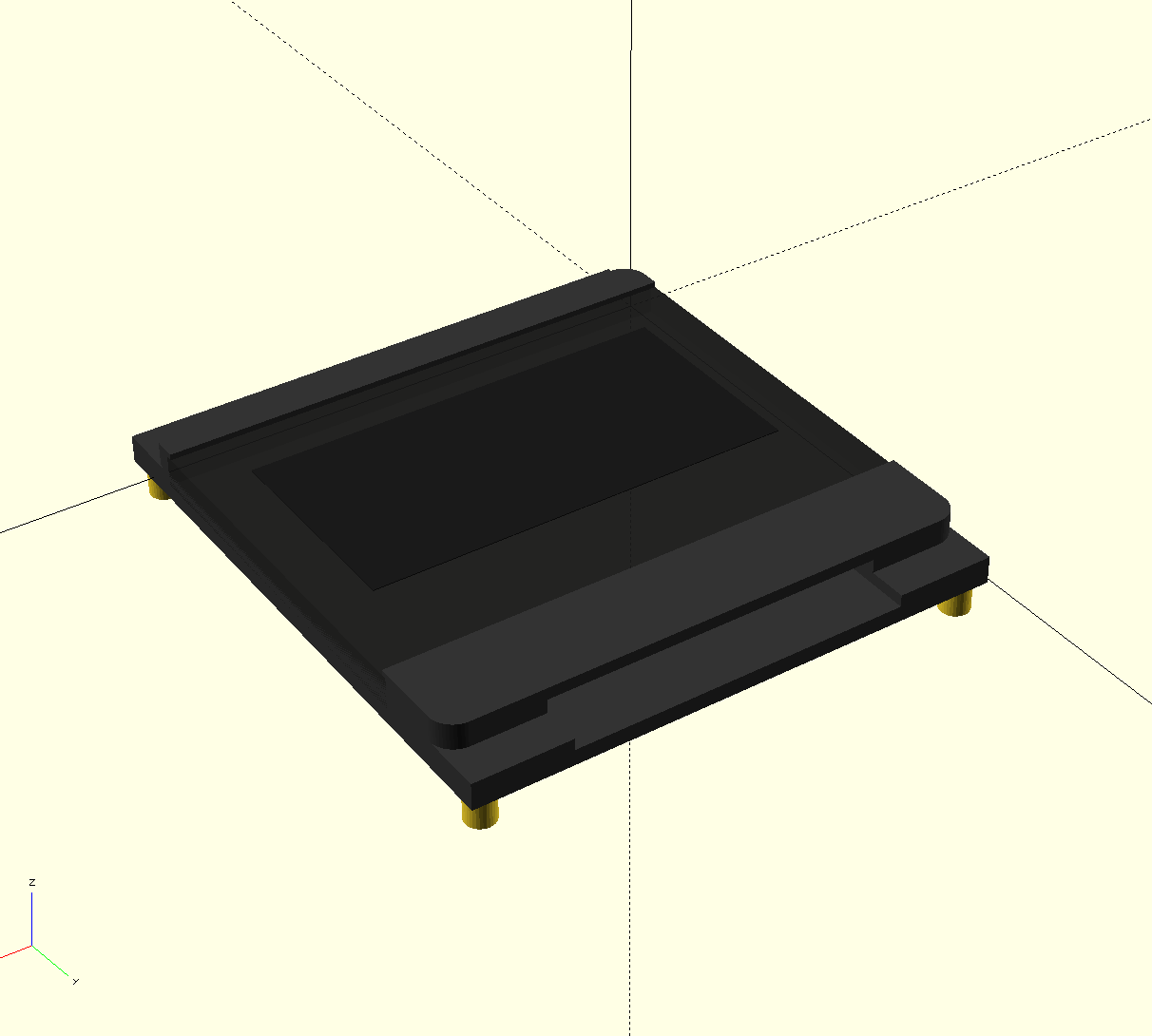
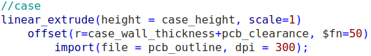
With the offset command I can make the extra space around the PCB for the case. All that missing is a linear_extrude and we already three dimensional representation:
If the outline or another physical property ever changes, I just regenerate the SVGs and run OpenSCAD again. That's all! I love that!
You can find the current version as usual on my git repo: https://github.com/thpoll83/PolyKeyboard/blob/master/case/right_side.scad
And as usual my apologies for the mess in the repo, I really need to cleanup the structure. It's just like my desk ;)
Remaining Manual Work
There are a few things that might need manual adjustment once a while, but it's really manageable:
- The logo as I just placed it loosely in the middle
- The wedge shape in the front
- The mount points for tenting (on the side)
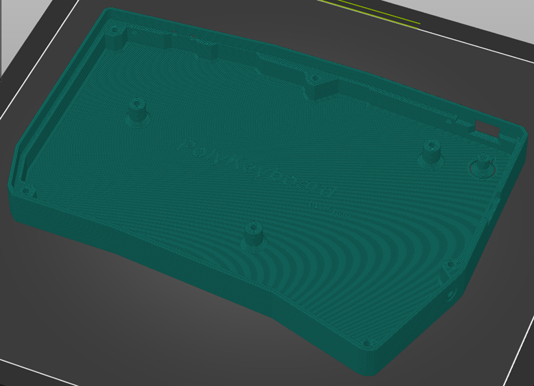
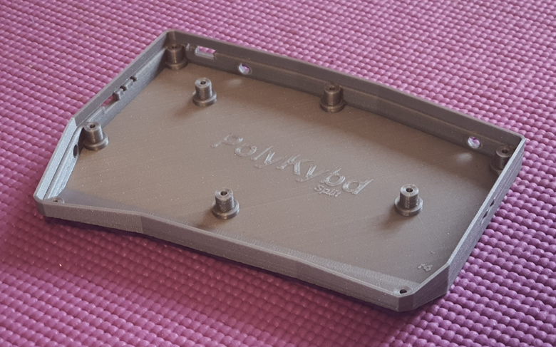
3D Printing
Of course I 3D printed the case and it turned out well:
I would like to show you with the new PCB, but the updated right version is currently in production and will take a few more days...
Discussions
Become a Hackaday.io Member
Create an account to leave a comment. Already have an account? Log In.