A true milestone today ! Just half an hour ago...
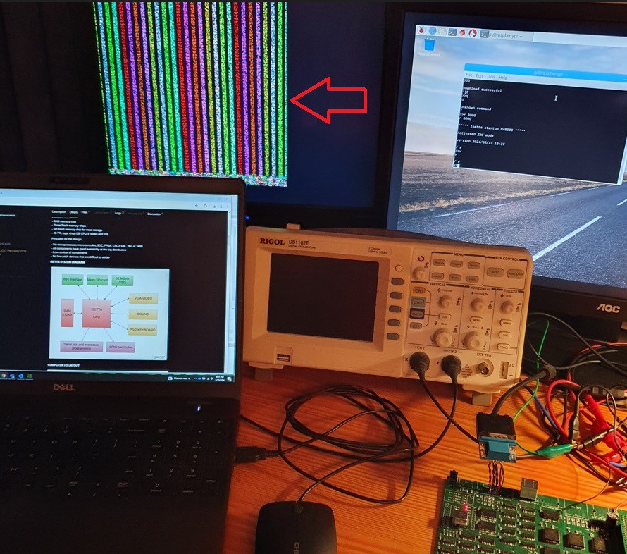
The picture shows my test setup, with a laptop, scope, Raspberry-Pi screen, and....
FIRST VIDEO OUTPUT !

It shows just a simple testpattern that I quickly made up. Colored bars and pixel patterns, and when I wrote it I had no idea how it would look. I did not bother to start the pixels at the correct distance from the sync pulse, so apparently I started much too soon since a the right-side, one-third of the screen is empty. (but I also just generated 60 characters instead of 80, to have simpler code).
The picture gets its stability from the timer interrupt on Isetta. The picture stays fully stable if I give Isetta commands via the Raspberry Pi screen. On the Isetta, there is no need for forcing your code in certain blocks with exact equal amount of cycles as in some other designs. (but of course, the interrupt code that generates the picture must have exact timing).
You can see on the picture that the video connector connects with wires to the pcb. That's because I used the wrong footprint for the 15 pin video connector. I had no idea that there were different types. The difference seems to be that one has a row distance of 2 mm and the other one a distance of 2.5 (or 2.54) mm.
Soon there will be characters on the screen !
Discussions
Become a Hackaday.io Member
Create an account to leave a comment. Already have an account? Log In.