TEXT MODE
In the last log I mentioned that there was video output.
A 80-column text mode was created. Each character is in a 8 x 8 pixel matrix. To make it better readable, a few empty scanlines are between the textlines. The VGA pixels are generated by the microcode.
At the moment this is mainly used as a text mode, although it is actually a graphic mode with 8 bytes of 8 pixels each. For each row of a 'character', there is also a color byte. The idea is that every character can have a different color (but since this is a graphic mode, each row of a character could have it's own color). The background color for a character can also change, but that's not fully implemented yet.
The picture shows how the system starts in the current version. It shows a few big colored fields to show some of the colors. At the right side you see some random colors, where you can see that each character can have a different color for each row.
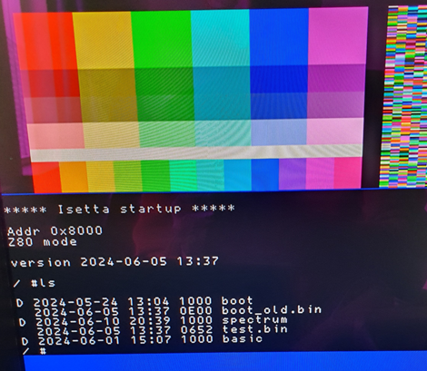
You also see how the file directory shows up. A line that starts with "D" means that this is a directory.
After I got this video mode working, I worked on the PS/2 keyboard input. The keyboard did only give a singe message after startup, always the same, and did not respond to key presses. After searching my keyboard on the internet, I found that some keyboards need a RESET message before they start working. In my case, I had to solder two transistors on the pcb to be able to transmit the reset message to the keyboard. But then it worked ! A Z80 program translates the scancodes to ASCII.
Isetta can now run with its own keyboard, video output and file system, without the need for the RPi !
ZX Spectrum video system
After I got that working, I spend some time making a video mode that behaves as ZX Spectrum graphics .
To test this, I downloaded the source of the game Manic Miner. I could only get this to work if I also found the explanation of Manic Miner source code. Here is the first result:
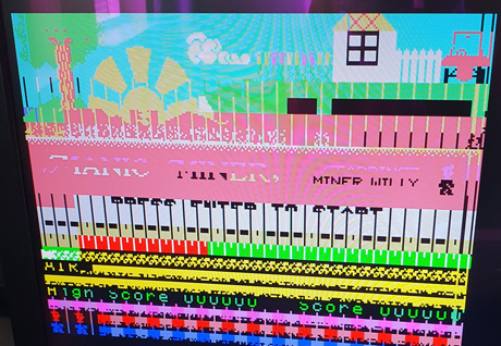
Obviously, not everything was working correctly yet. There were vertical lines at every character boundary, and apparently the attribute bytes of the lower part of the screen were not correct.
It could be traced (within reasonable time) to a failing LDIR (load-increment-repeat) instruction. This is used in the game to copy big blocks of bytes to the screen, with a single instruction. The LDIR, that is implemented in microcode, was designed to check for an interrupt periodically, and in the case of interrupt set the program counter two steps back, and after the interrupt resume the copy operation. But it didn't work correctly with interrupts.
The LDIR was a highly optimized piece of microcode. At ten cycles per transferred byte, it loaded the byte, stored it at the destination, incremented the HL source address (with carry between low and high byte), do the same for the DE destination address, decrement the BC byte counter, test if BC is zero. And also check the interrupt signal at every transferred byte.
I took the fast way out. I grabbed a RST instruction (0x20) and did put a copy routine there. In the source of the Manic Miner, I replaced every LDIR with a RST 0x20. Followed by a NOP to leave addresses unchanged. Getting the bug out of the LDIR instruction was put on the TODO list. Now I got this:
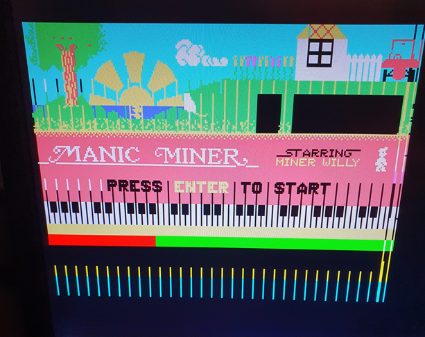
Already much better !
I could also see on the piano keys that the start-up tune was playing (but of course I have no sound yet). Also, a scrolling message was visible. After that, the program crashed. More debugging to do !
Discussions
Become a Hackaday.io Member
Create an account to leave a comment. Already have an account? Log In.