 Arya
AryaThe phone has to be accessible, and by that I mean that the components should be easily sourceable. What are the criteria for this?
Less obscure components. If there's somebody not able to get the DC-DC chip or specific inductor I'm using (say, shipping is more than the IC costs), I will try to do at least one of those things:
- make it optional to use (like I'm doing with the audio buffering on the new board)
- make footprints compatible with other more popular ICs/breakouts
- make it work some other way
Boards should be easy to make. That means two-layer boards, using PCB design settings that are easy for board houses to make and using dimensions that are typical limits of board houses (also, encouraging pamelizing boards). While I'm not aiming to make the boards etchable at home (this task is high effort/small advantage for the project), I encourage anybody who needs this feature to try and make the boards suitable.
Components should be easy to solder. No BGA, LGA or anything that needs a heat gun. Unless absolutely necessary, I'll avoid this like a plague. BGA and LGA are very nice technologies, but I'll leave them to people capable of actually soldering them right and having the right tools - and that's a pretty small number of people, if we look at who this phone is aimed for. Also, breakouts. If a screen has (x < 0.8mm) FPC pitch, needs 10 or more passives to operate, as well as a boost converter - I'll just pick the one with a breakout that has 8 pins, with everything already soldered and, hopefully, tested.
Let's see some examples.
The GSM module
SIM800L has this nice red breakout made by Chinese. It's small, yet exposes the most basic functions necessary. Also, it's 6$. For example, #DIY GSM arduino FR4 cell phone uses it.
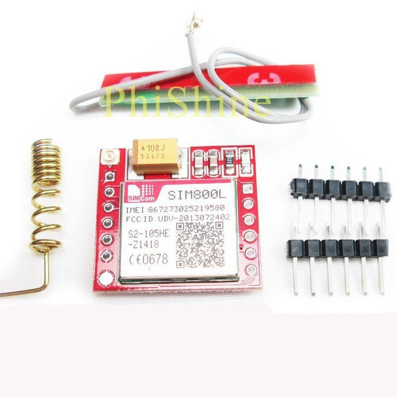
For 6$ you get this small breakout board with 2.54 headers, a big SMD capacitor that you'd definitely need, two antennas, all the passives, NET led and easy-to-use SIM socket. That's economy of scale in action - just imagine how much it actually costs at TaoBao!
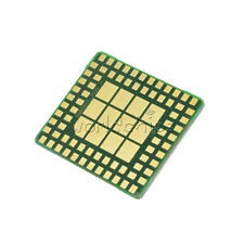
Of course, you can get the bare module for 4$ from the same eBay, it'll be LGA (same as on the breakout). What's LGA like?
But, of course, that's simple stuff and nobody would argue with that. A better example?
Display breakouts
So, theoretically I could limit the phone to one screen. That's a good decision, and that's the one I'm going to take now in terms of hardware support. What's about hardware? There are multiple breakouts on eBay. Here are pinouts of the cheapest breakouts.
| Type | Pin 1 | Pin 2 | Pin 3 | Pin 4 | Pin 5 | Pin 6 | Pin 7 | Pin 8 |
| TFT 1.44/1.8 | GND | BL | VCC | SCK | MOSI | DC | CS | RST |
| Nokia 5110 | GND | BL | VCC | SCK | MOSI | DC | CS | RST |
| Color SSD1331 OLED | GND | VCC | SCK | MOSI | RST | DC | CS | |
| 1.3 SH1106 OLED | VCC | GND | SCK | MOSI | CS | DC |
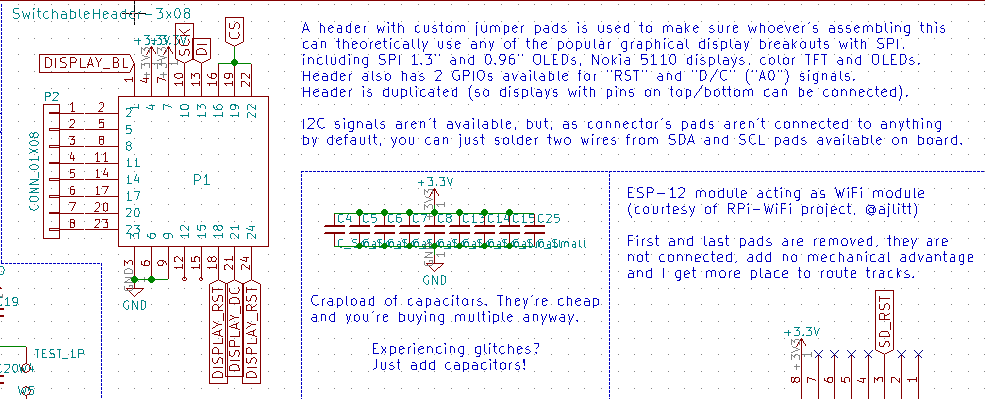
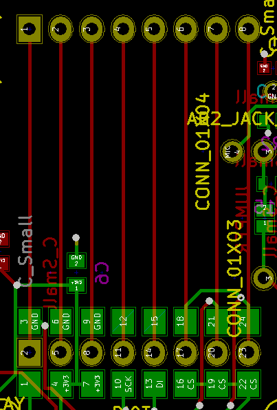
You get the idea? I've made a custom header footprint that allows different breakouts. How it looks like on schematic and on the board?
How does the alpha board's display header look when a SH1106 OLED is soldered on?
In the end, I have a simple way to support multiple displays - leveraging Chinese breakouts, the fact that most displays use SPI and some solder jumper magic.
WiFi module
While it's entirely possible to route a ESP8266/8285 chip on my board, as well as add an antenna, it's much, much easier to just add a ESP-12 module, as an ESP8266 chip would likely need to be reflowed, use lots of passives and wouldn't even be cheaper for the end user to get - again, economy of scale. The ESP-12 is kinda bulky - as @Tisham Dhar suggest, it's possible to use a small ESP8285 breakout and save some space. However, the ESP-12 modules are manufactured in such large quantities that they're getting cheaper and cheaper to source - and even being resold by local distributors in some smaller countries.
Audio output
I went the proven way - using PWM to get audio output, just like Raspberry Pi versions do. There are two ways to achieve this - old and noisy, and new and less noisy. Let's compare the schematics.
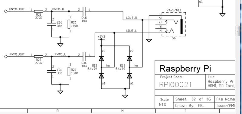
Old way:
New way:
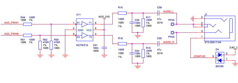
images from adafruit.com
See the common part? The "two resistors and two capacitors" part. The new schematic just has a buffer, a voltage divider before that and separate power supply, the other part's the same. However, the buffer IC and small 2.5V voltage regulator might be hard to source for some - while some will absolutely need to get rid of constant quiet noise. What's the solution?
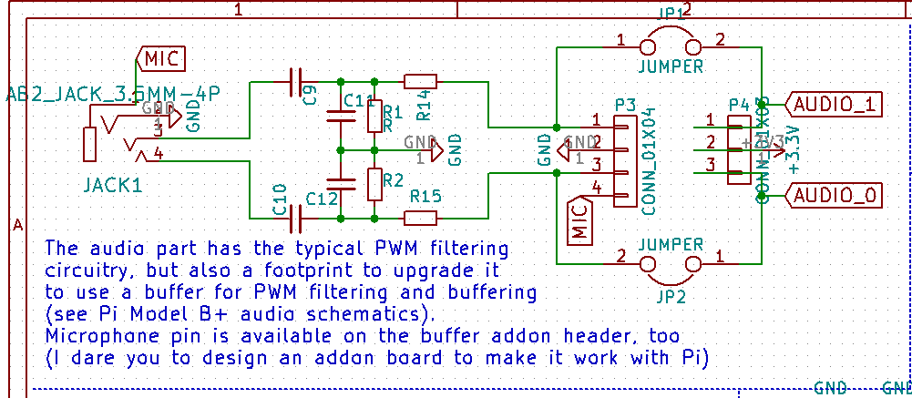
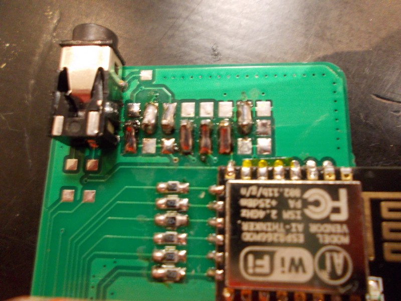
How the board looks:
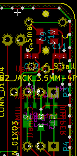
The pin headers make it possible to add a small "audio buffer" addon-board in the future, while being easily jumperable if you don't want the buffer to be there. I think I should probably add the ESD diode footprint as well. It's quite optional, but this is an outside-facing interface after all and problems might appear, so it'd be nice to give a possibility to add the interface.
Real-time clock IC
Those ICs typically use SO8 footprint and the same pinout. The only problem that might appear if somebody wants to go "full cheap" and use some DS1307 chips, which use 5V. Possible solution for this:
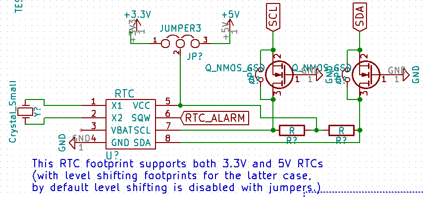
I might end up scrapping this if it proves to be unpopular, but for now, the board space taken by this will likely be very, very small.
Keypad side switches
I was searching for SMD side switches on eBay, to make some buttons on the side of the phone - you know, camera, volume buttons and such. I found two most popular types - with 4 and 2 pins, no other differences. Say, a typical button connects pin X to pin Y upon keypress. Those with 2 pins have pin X on one side and pin Y on the other side. Those with 4 pins have one pin X and one pin Y on each side. Let's show you what I'm talking about.
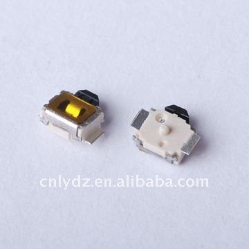
2-pin button
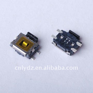
4-pin button
The only difference is that buttons I've got are different from those pictured - both have 2 plastic pins on the bottom, so that part was similar in my case. I want users to be able to use both 2-pin and 4-pin buttons. My solution?
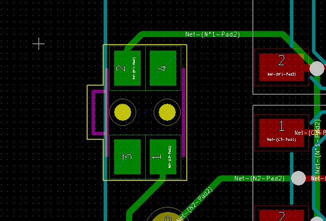
Two of four pins are NC so pins never short-circuit, no matter which buttons you're using.
This is not the end of making footprint choices and searching for suitable parts. I still need to sort out DC-DCs, USB connectors issues (usual USB full-size female connectors are huge), Li-ion charging and some more issues. I do hope I've given enough insight into how I'm making phone as accessible as it is when it comes to sourcing components.
Discussions
Become a Hackaday.io Member
Create an account to leave a comment. Already have an account? Log In.
I know a you're not looking to connect a USB-OTG port, but could you use a micro-USB header with some protection circuitry and require a micro-USB to USB A female cable? That may completely go against your accessibility goals so I understand if the answer is no.
Are you sure? yes | no
Hi! I, so far, went with a full-sized port - in my experience, such an adapter is just one more thing that can break, and microUSB ports on boards are typically hard to repair (and would be harder to source and solder for some people). Furthermore, if going with a microUSB for both host and charging, it'd require additional circuitry and this is challenging so far - there's a lot to be crammed on this small board. For now, there's a MicroUSB for charging and a full-sized USB for devices - I'll see how my usage experience goes =)
Are you sure? yes | no
Liked on account of minimizing micro-USB's prevalence :)
Are you sure? yes | no
What type of usb port are you planning on using? A newer type C connector is definitely smaller than the older but more common type A connector.
Are you sure? yes | no
Hi! It's definitely the old type A, there's no need for C here - RPi doesn't even have U3.0 lines, the peripherals are not as available, and needing adapters to plug in a flash drive is just silly. Also, older USB ports are hundreds of times easier to source.
Are you sure? yes | no