 Arya
AryaEven though I've put a lot of work optimising ZeroPhone for everyday usage, self-assembly and manufacturing, there still are things we can do better in the next revision. Let's go through them, so that you can see the final changes I need to make to the boards, and things I need to figure out before the crowdfunding!
This list is a result of me carrying a ZeroPhone with me through this year - and, therefore, fixing these problems will make sure your ZeroPhone lives as long as possible and is not merely some kind of gimmick that dies after a couple of months. Most of these problems are either fixable or have workarounds - if they didn't, I wouldn't have had been able to assemble the Gamma PCBs. However, they will be problematic for new people, so I have to make sure to eliminate as much of those problems as possible for the next version - to properly achieve the ZeroPhone "self-assembly" goal, making the assembly "as easy as possible" and not just "possible".
Charging and protection boards
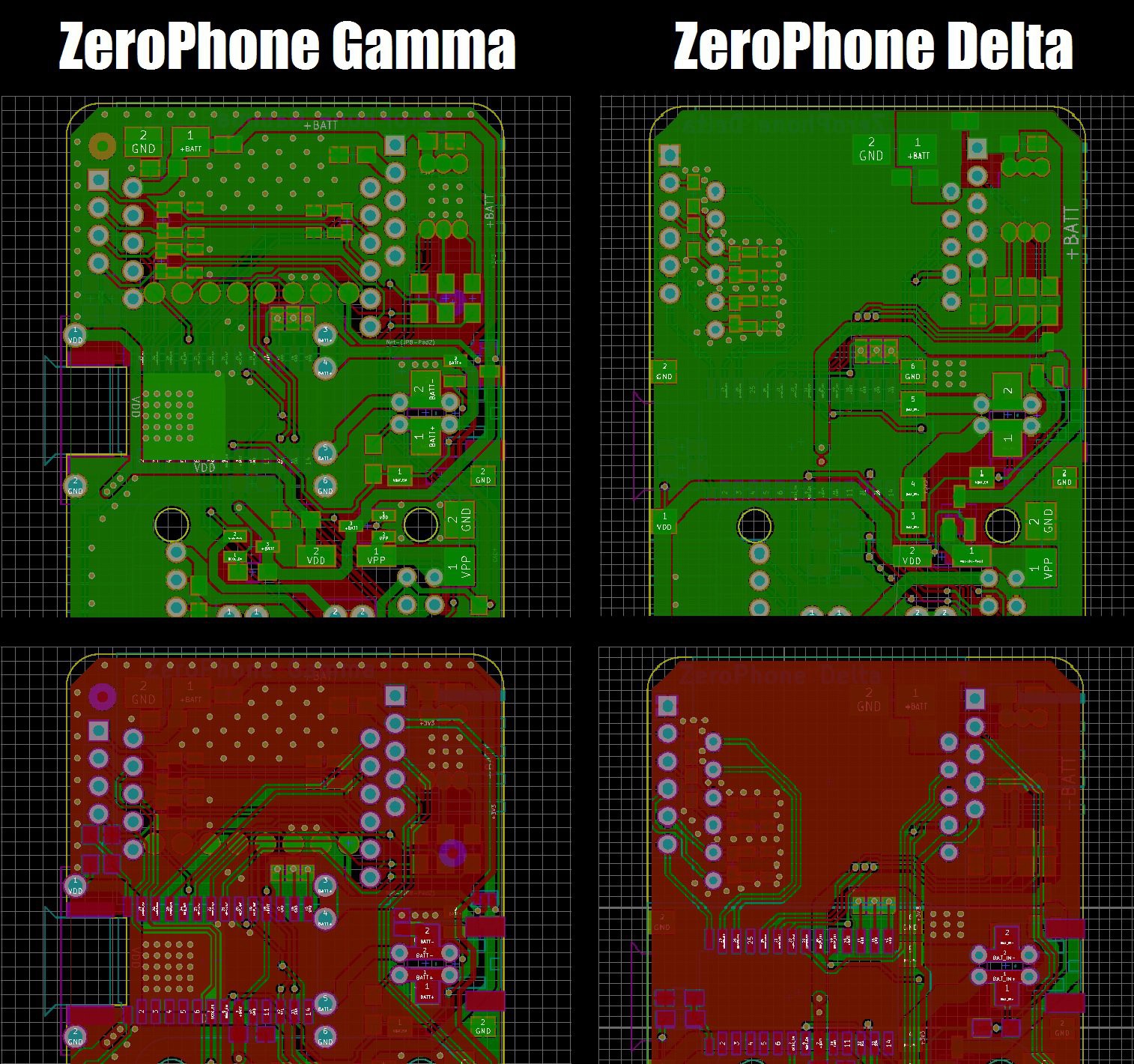
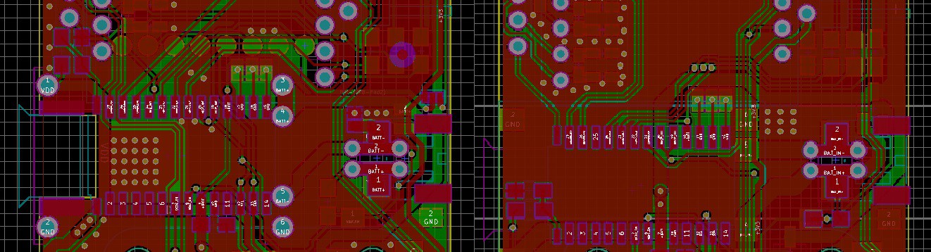
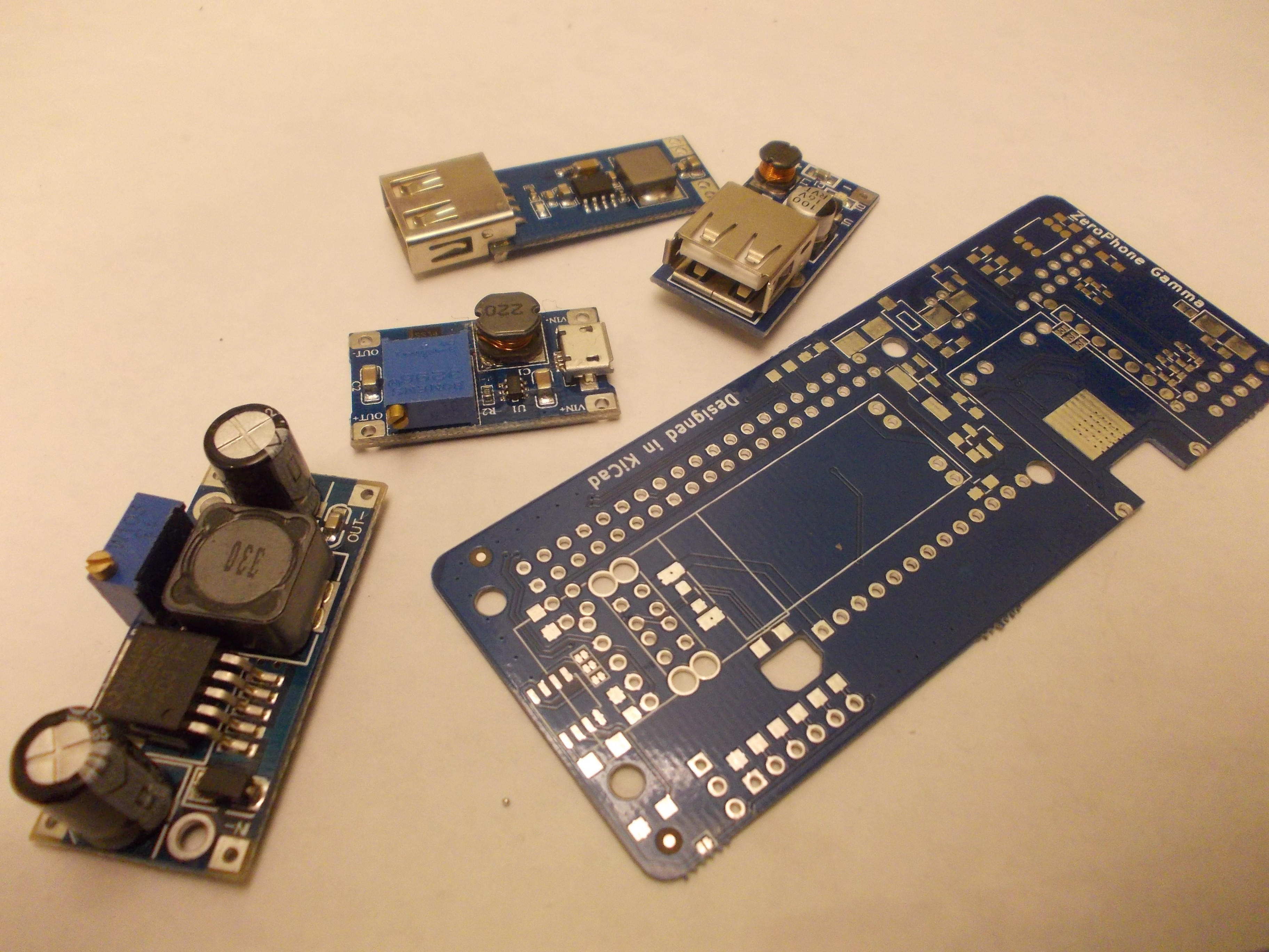
We use popular modules from China for the ZeroPhone battery charging and protection. I had problems with the way those modules had to be soldered on the back board - it wasn't straightforward, and it wasn't easy to get done. So, I've flipped the footprint - now it's compatible with more module types, and it's much easier to solder the modules on - the board layout also became much more straightforward, since power traces used to be crossed and now they aren't! The component side of the modules is now exposed to the outside of the phone, though - I'll have to make sure this doesn't cause problems, such as short-circuits (possibly, release a 3D-printable cover).
In addition, there were stability problems with a new version of these modules. Beta boards were using an earlier version:
For Gamma boards, however, I used slightly different modules, a newer version - I ordered them by mistake, so I quickly changed the footprint to fit the new modules in order to avoid ordering the older ones.
That turned out to be a bad idea - the newer modules seem to not function as well as the previous, some of them randomly fail (luckily, they fail safe). It happened to some of my ZeroPhones, and it also happened to some of the ZeroPhones that I sent out (which resulted in the person having to send it back, for me to repair, and that's something I'd really like to avoid). That's not acceptable - if the module is broken, ZeroPhone cannot operate from the battery at all - or it switches off randomly, which is even more annoying. Fortunately, the new, flipped footprint allows for all kinds of modules, so it should be easier to find a suitable board now!
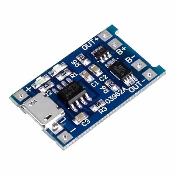
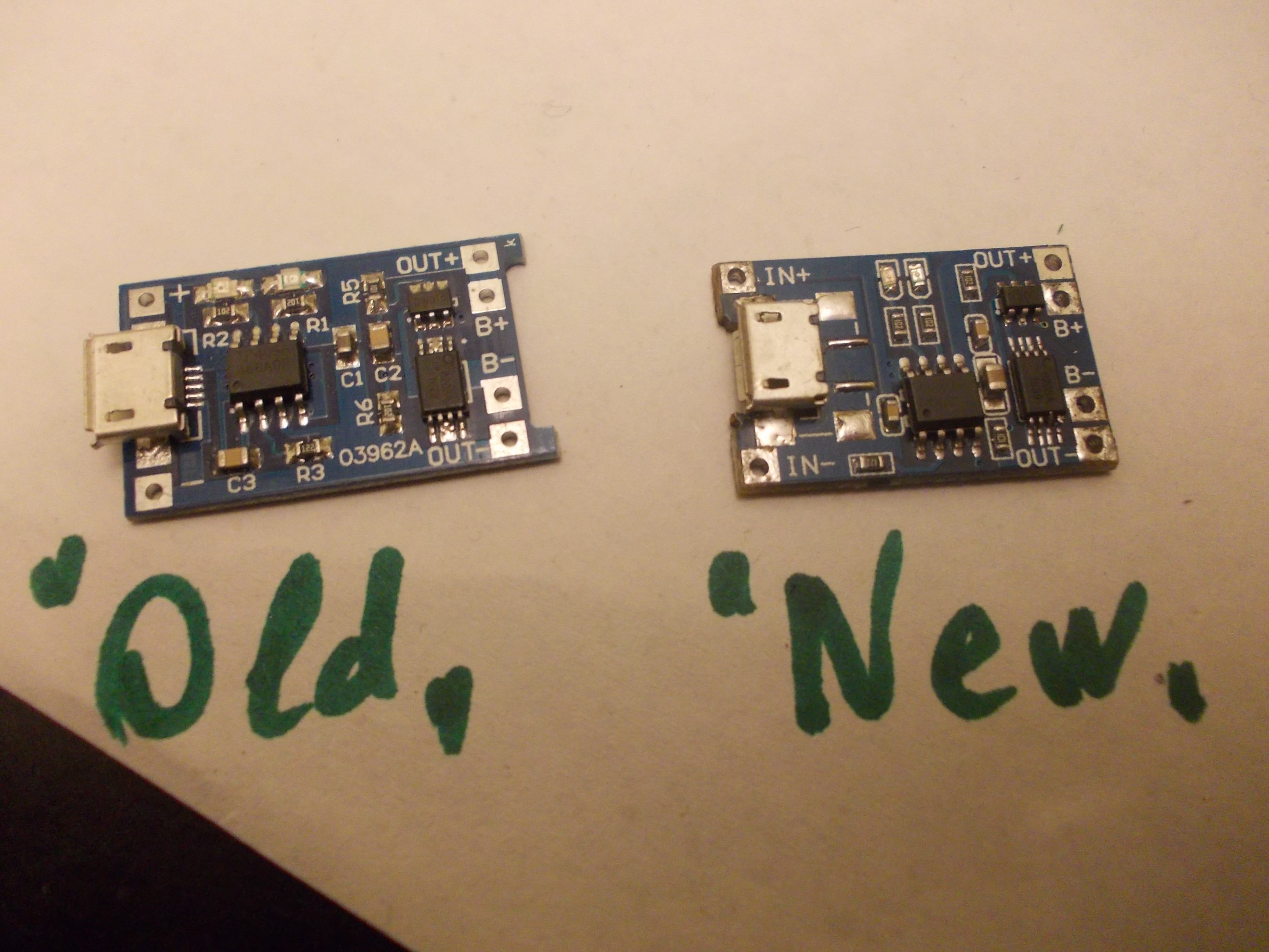
 During the manufacturing, we'll need to find a way to either find a reliable source for these modules, or to manufacture our own (I've already reverse-engineered the schematics and the PCB, thankfully, and I'm asking for manufacturing quotes) - as a backup plan in case the commercial modules are no longer suitable for us. I've also tried understanding the problem by comparing "old" and "new" modules - I've checked the schematic and it's the same (the boards are slightly different, but the changes are minimal), so my guess is that the "new" modules are using cheaper components, which causes the failures. But, just in case, I'm going to see if there's a way for us to source these boards reliably.
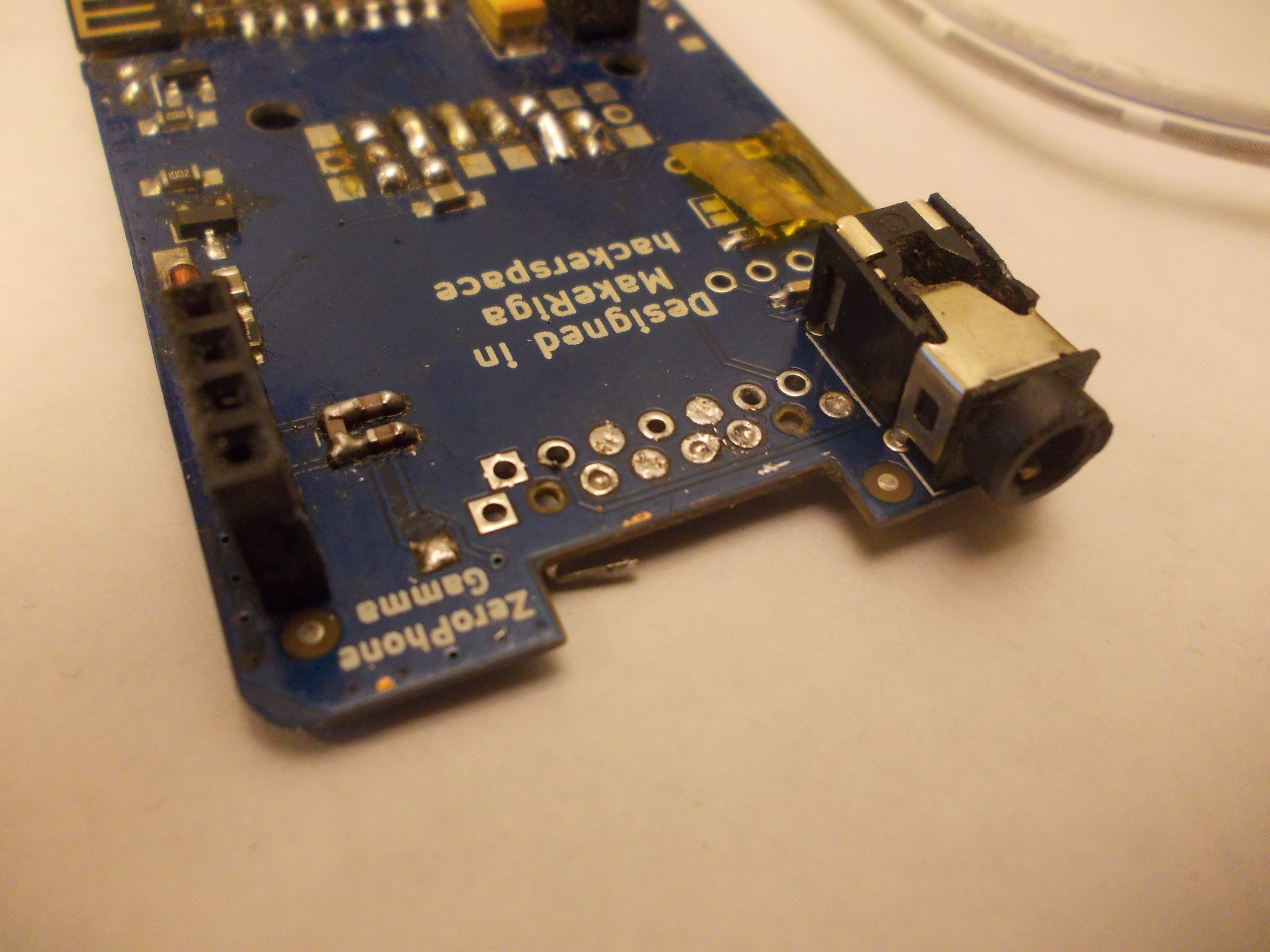
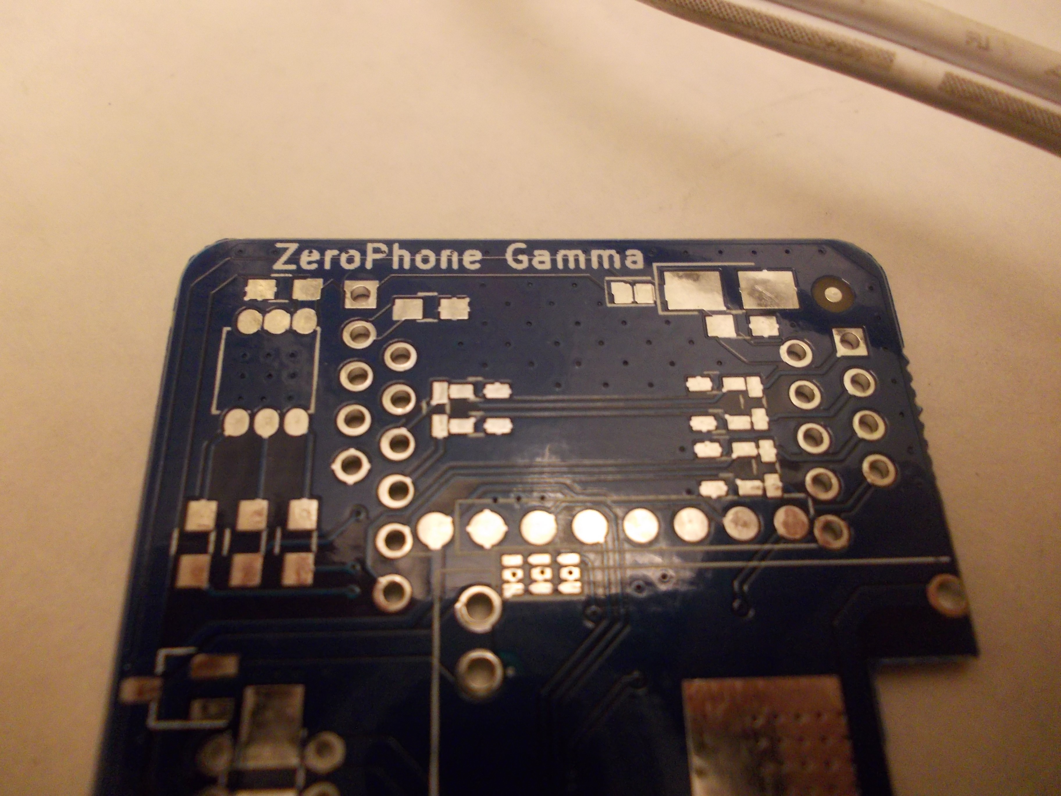
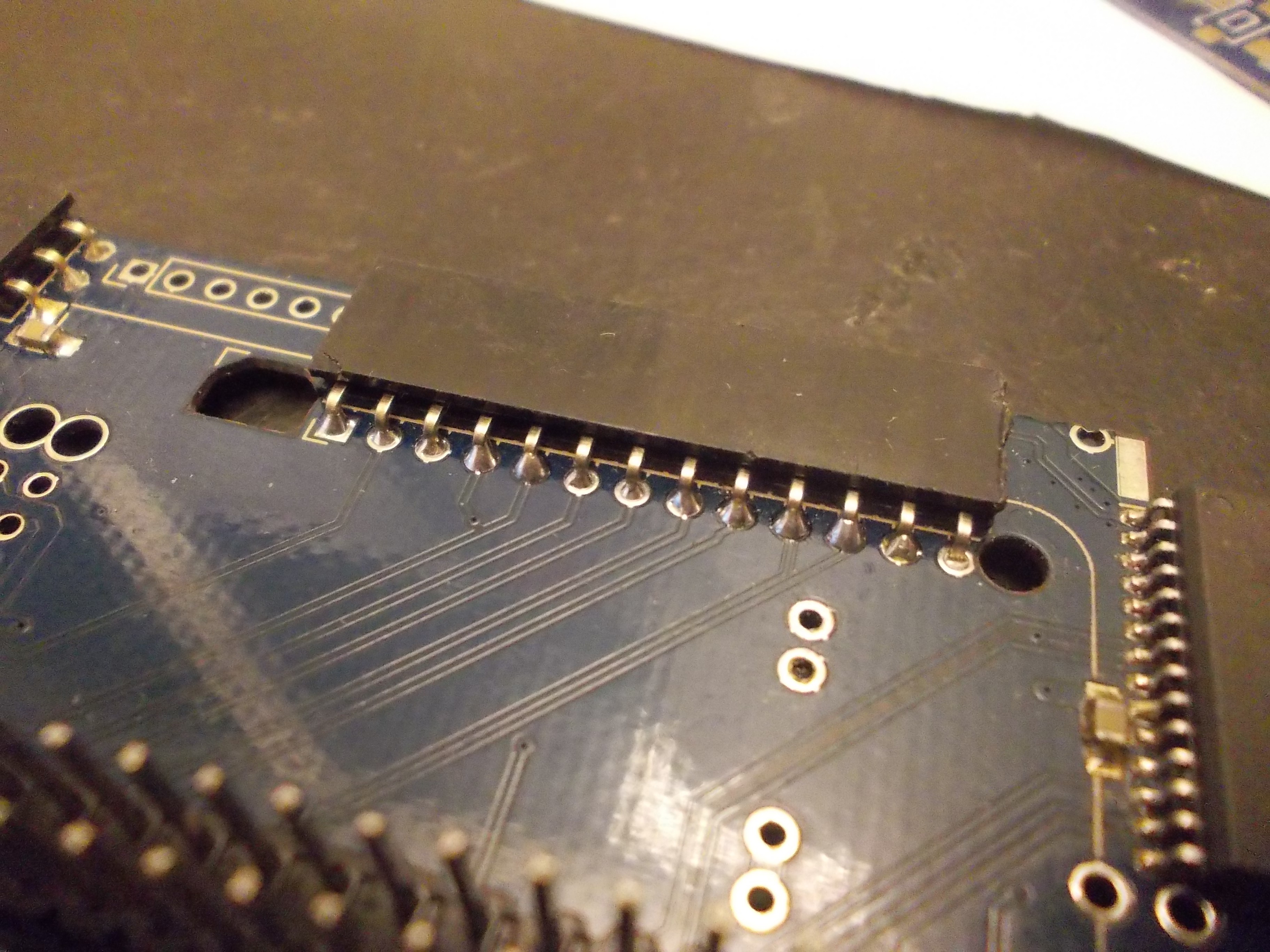
Reworkability
It turned out that current ZeroPhone PCBs might have some problems while doing repairs - traces breaking, pads being lifted etc. Generally, it will only happen to low-quality PCBs - but it's hard to make sure the PCBs you're ordering are of sufficiently high quality (and if you're ordering from a place like DirtyPCBs, it's likely your PCBs won't be good enough to survive overheating). This is bad, since it makes ZeroPhone less repairable - in the end, I have two back boards and one front board that are unusable because too many pads got lifted, and I also have some more that need wire fixes because of pads that fell off. Granted, many problems appeared because of me overheating some of the boards during reflow - but it's a mistake that could be easy for people to make, and if it's something we can safeguard from without any big problems, why not adjust the boards for that? I will have to check whether my modifications will result in a design that's still easily manufacturable, though.
In addition, many pins are tricky to solder. The exposed copper ring around the pins is small, so it's hard to heat the copper up, which results in having to wait longer to make each solder joint - while the flux is burning out and the part is needlessly heated, which, again, can contribute to the pad eventually detaching. I will likely enlarge most of the pads on the connectors, making sure that soldering will be as quick as possible.
Converting back board to a 4-layer PCB
The back board is the most complicated ZeroPhone board - it has power management, GSM modem, the GPIO expander and expansion ports on it. So, the layout is cramped, and making big changes is tricky. I feel like the layout is pushing the limits of 2-layer PCBs (and many people have told me the same over the last year), and at some point it might result in stability issues. While my charger&protection board and GSM breakout changes have improved the situation dramatically, adding two layers would help a lot - the internal layers could be used as ground/power planes, so it'd be easier to layout numerous signals present on the back board, and it could decrease the inevitable noise that all the signals and power paths will produce. Also, it would allow us to better layout the board, so that adding features to it would be much easier in the future.
The downsides? 4-layer boards are somewhat more expensive and harder to order for hobbyists. You can't panelize them as easily, which means that you wouldn't be able to get by with ordering two 2-layer 10x10cm panels, and would have to order two 10x10 panels + a 4x10cm 4-layer board, which would result in a $28 increase in case of ordering on DirtyPCBs, or double the price in case of OSHPark.
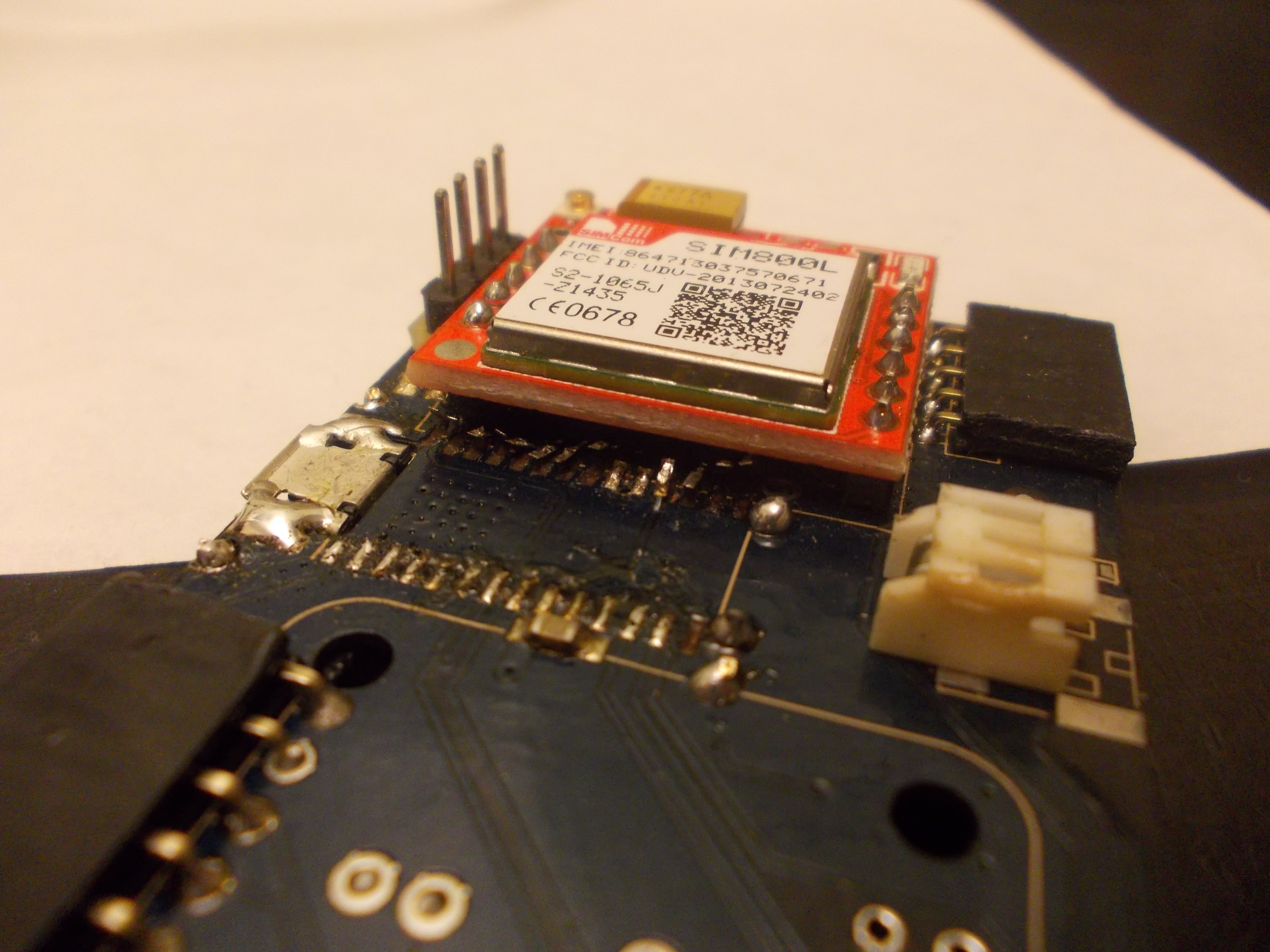
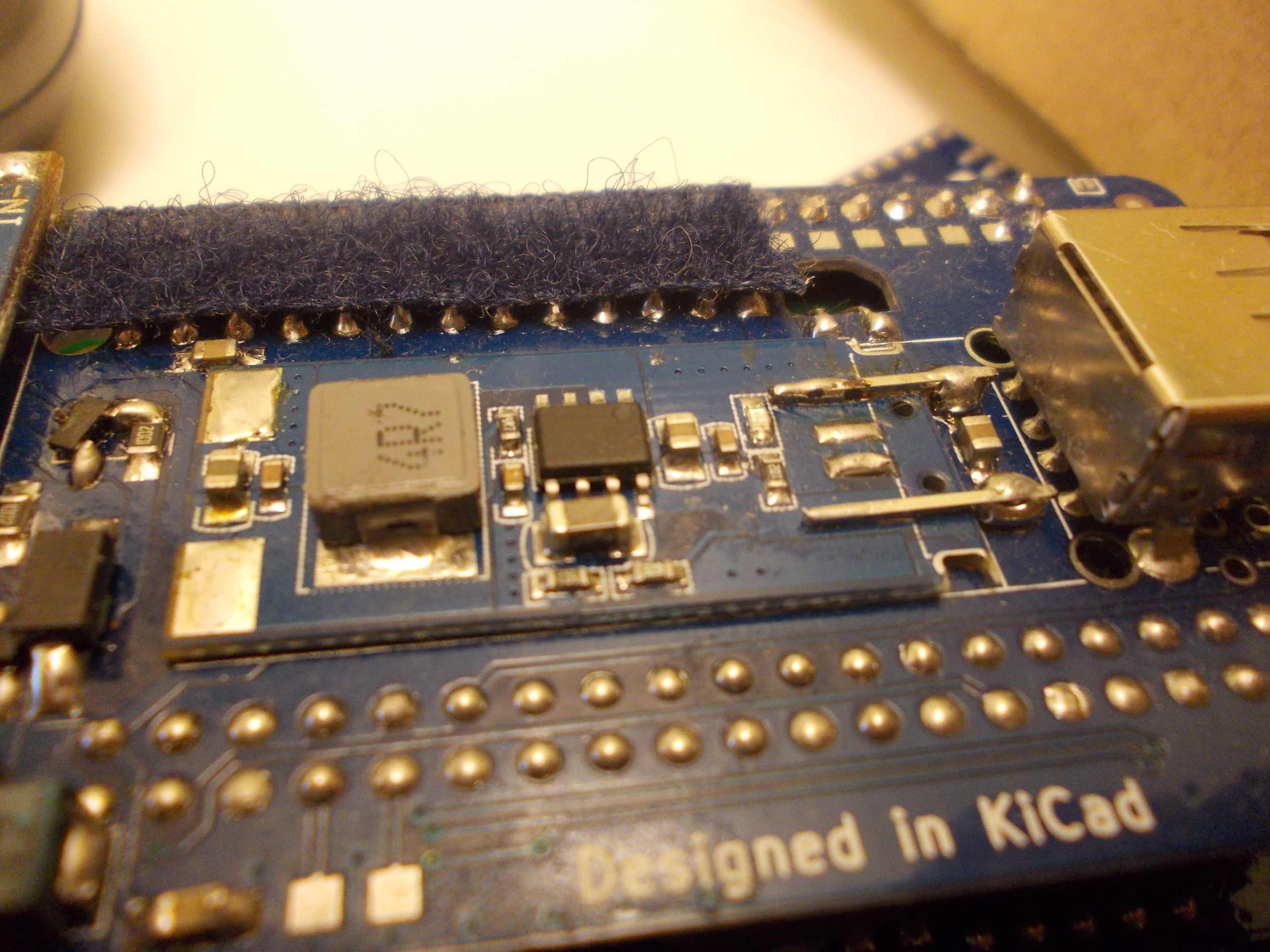
GSM modem
The GSM modem connections on the back PCB were crossed - audio went from right to left, and power&control signals went from left to right. This is not good - it introduces noise in the audio lines (which was one of the issues prominent on Gamma ZPs I assembled), as well as makes the layout less straightforward. So I've flipped the modem breakout vertically. This means that the SIM card holder is now up, and the modem itself + the antenna connectors are now down (between the modem breakout PCB and the back PCB). The new placement improves the layout, but there are two new problems: 1) the big capacitor on the breakout PCB is too tall, so it likely will bump into the PCB 2) the antenna will be harder to attach, since now it will have to be inserted between the back PCB and the module PCB. I hope I find some kind of solution to these two problems, since, I have to say, the layout is considerably better now and I don't feel like going back =)
Speakers
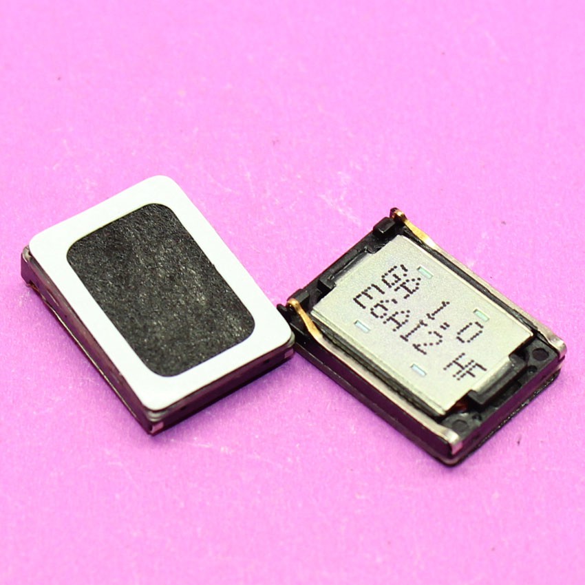
From the start of ZeroPhone, I never really factored speakers in, I hoped to use something like ubiquitous Nokia speakers when the time comes. It turns out I can do it, but there's a trick - most of these speakers are not meant to be soldered, but instead to be tightly sandwiched between the phone's case and the phone's motherboard, and in case of ZeroPhone they can only be soldered. I could theoretically use some kind of round speakers with wires already attached, but that'd limit our options, and it might not have as good of a sound quality. Also, the space above the display is already pretty limited - a round speaker just won't fit, since they tend to be pretty large. So, I'm looking for a solution to that - the Nokia speakers are definitely solderable, so I'll likely make a "carrier board" to solder the speaker on; that board would, in turn, be soldered onto a ZeroPhone front board. This solves the problem, but I have to see if this is *the* solution.
13-pin header
On back boards, I've used a 13-pin female header for an extension port, and I forgot to check if these are commonly available - turns out, they aren't. Fortunately, I can easily make it 12 without losing anything of significance (though TV-OUT will have to be available on its own header, likely unpopulated by default). Also, replacing a 13-pin header with a 12-pin one will actually make the board more manufacturable, since the plated holes are located too close to the board cutouts. So, 12-pin headers it is!
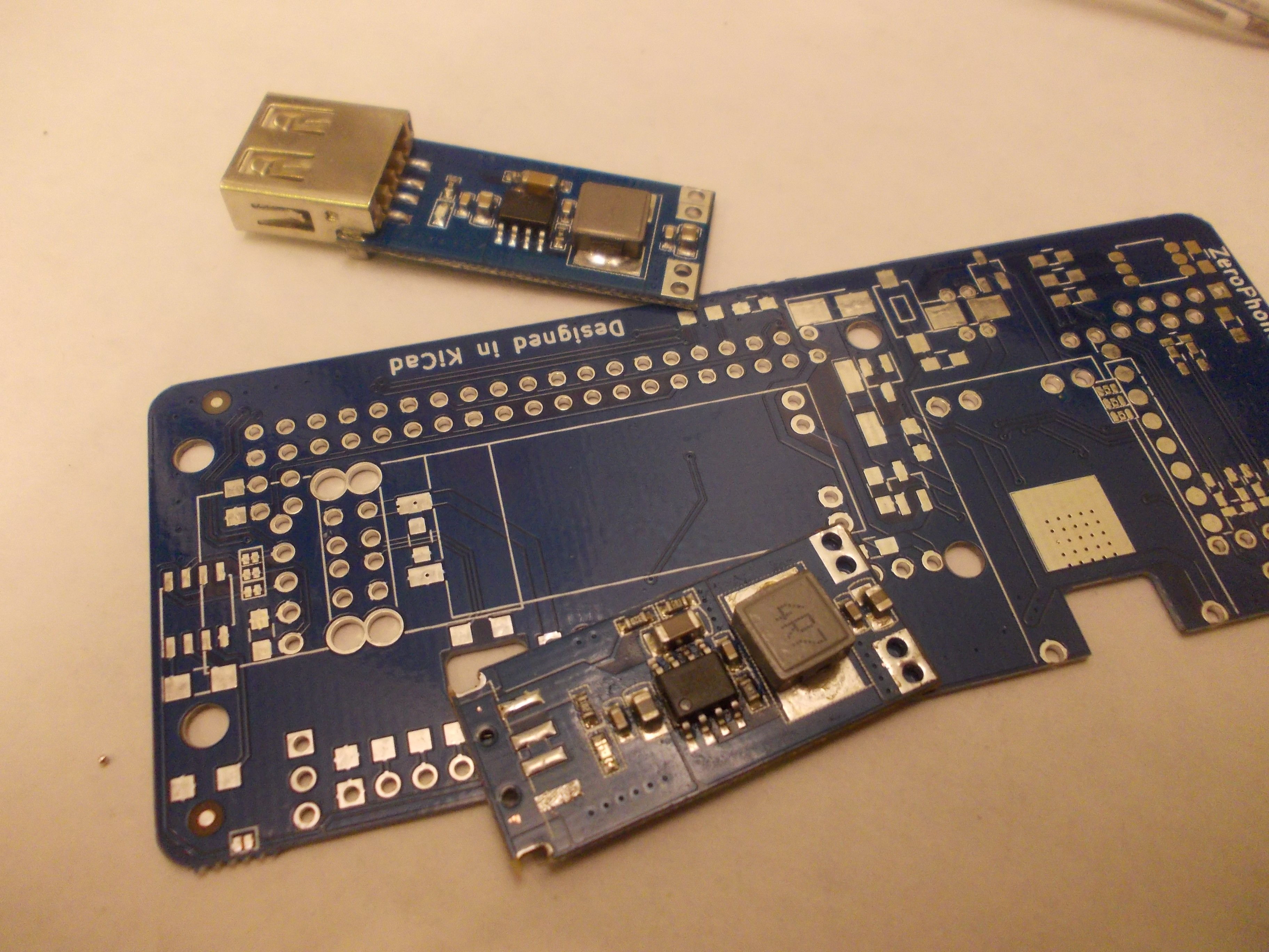
5V step-up (DC-DC) module
There's an auxiliary, but very useful function on the ZeroPhone - a 5V power supply. It's done using a cheap step-up module, again, from China. Unfortunately, the module itself is not very well-suited for soldering - it can easily be done manually, but it's not as easy to do it automatically. There are two steps that are hard to automate - first, you need to remove the USB port from the module, which involves tearing its tabs off with pliers, then desoldering the 4 remaining pins with a soldering iron. Then, you need to bridge the 5V and GND pins to the ZeroPhone back PCB - with either a piece of wire or metal from a pin header. An in all, it's not easily automatable. I'm wondering if, for mass-production, we could even order these modules with USB ports not soldered on...
Then there's another question - maybe we should switch to another DC-DC module? This one, despite its size, only really handles about 0.5A, which is really not that much. Using another module could allow using a ZeroPhone as a powerbank, for example - which I've already done multiple times, and the 0.5A limit is kind of noticeable. However, this module is very straightforward and easy-to-use - it's easy to get, easy to solder, it doesn't need configuration (which can be error-prone) and it, in general, just works. So, an alternative would be to develop a mod board that'd optionally replace this DC-DC, providing higher current (and maybe more convenient soldering).
The last thing is power-related. The DC-DC can't handle 5V on its input, so it can't be powered from VSYS bus (3.3V-5V) - as a result, it's powered from the VBAT bus, like the GSM modem. This means that, while ZeroPhone is charging and DC-DC is turned on and powering something else (say, USB-WiFi), the charger is not only charging the battery, but also powering the DC-DC - this, at best, means that the charger never detects when the battery has finished charging, which is something best avoided (there's an overcharge protection on the charger board, so it's more of an inconvenience than something dangerous, though). We could avoid this issue by making the 5V output switch to the charger input when the ZeroPhone is powered on - at its simplest, it could be done with a mechanical switch - but I'm thinking of a BJT+FET-based arrangement, since we already have those in the BOM and an automated solution would reduce the possibility for human error.
Pi Zero soldering
This is one of the most problematic areas, in my opinion. The Pi Zero needs to be soldered onto the back board, onto a male pin header - and the front board then connects to the same pin header. The Pi Zero wasn't really meant to be soldered that way, but that's not the big problem - if you add too much solder, the front board won't plug onto the pin header fully, and won't have a good connection. In order to properly solder the Pi Zero onto the pin header, therefore, you need to control the way you're touching the soldering iron tip to the Pi Zero PCB and pin header while soldering, the amount of time you're heating the pin up and the amount of solder you're adding to it. It's also tricky to fix a mistake once you've made it - you need to either use the solder wick or tap the board onto your desk while solder is hot (causing the excess solder to fly away). This is one of the problems that make it hard for me to offer a large number of fully-assembled ZeroPhones during the crowdfunding - but it's also something I don't really feel comfortable leaving to the user to figure out, since if you screw this soldering up completely, it will be really hard to fix. So, I'll also look into automating this process somehow - even though I don't have an idea on how to dispense the solder paste onto the PCB properly.
In addition, at the moment it's necessary to adjust the pin header - make it so that the 40-pin header ends are flush with the back board. It's necessary because, otherwise, the front board's female header might not make proper contact with the male pin header - at least, it's happened on one back board that I assembled recently, experimenting with pin header lengths. I will be investigating it further (since I have other experimental board that makes contact with the female header just fine).
Display breakout traces breaking
The ZeroPhone has an OLED display breakout PCB on the front board. This PCB is only attached to the front board because it's held by a row of pin headers. Unfortunately, when something is pressing on the display (say, you have a ZeroPhone in your pocket), the resulting mechanical connection flexes unnaturally. This results in PCB traces and plated holes on both PCBs being stressed, which leads to traces breaking (I've already had a couple of display breakout PCBs fail this way). To solve this, we need to make sure the connection doesn't bend - from what I've gathered, we need to put some kind of spacer under the display, so pressing on it won't stress the solder connection, but only the spacer. The spacer, unfortunately, has to be of specific thickness, which makes it harder to have lasercut spacers (as materials for lasercutting aren't usually available in arbitrary thickness) - they will have to be 3D-printed, as a result. So, a 3D-printed model will be designed soon!
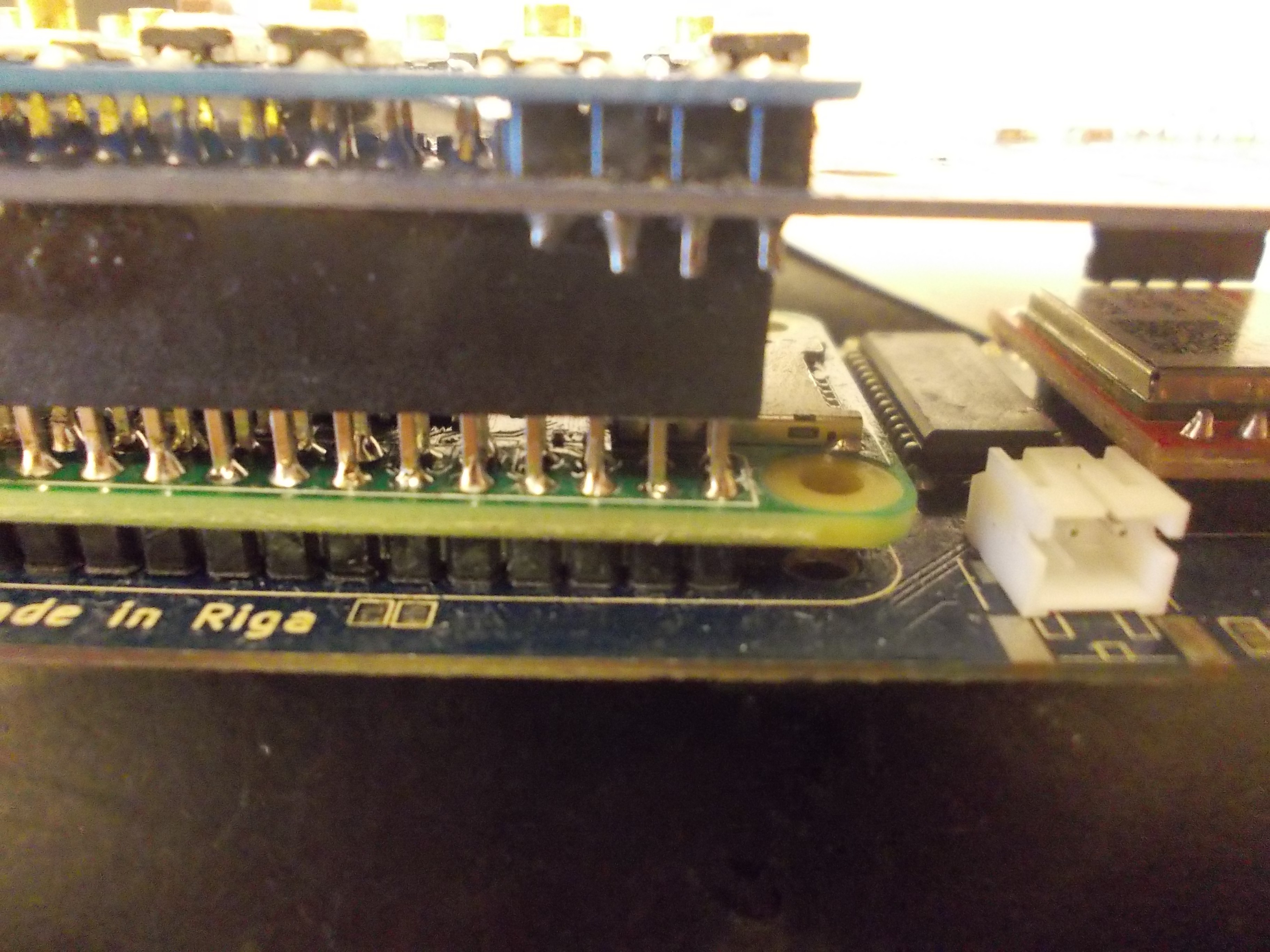
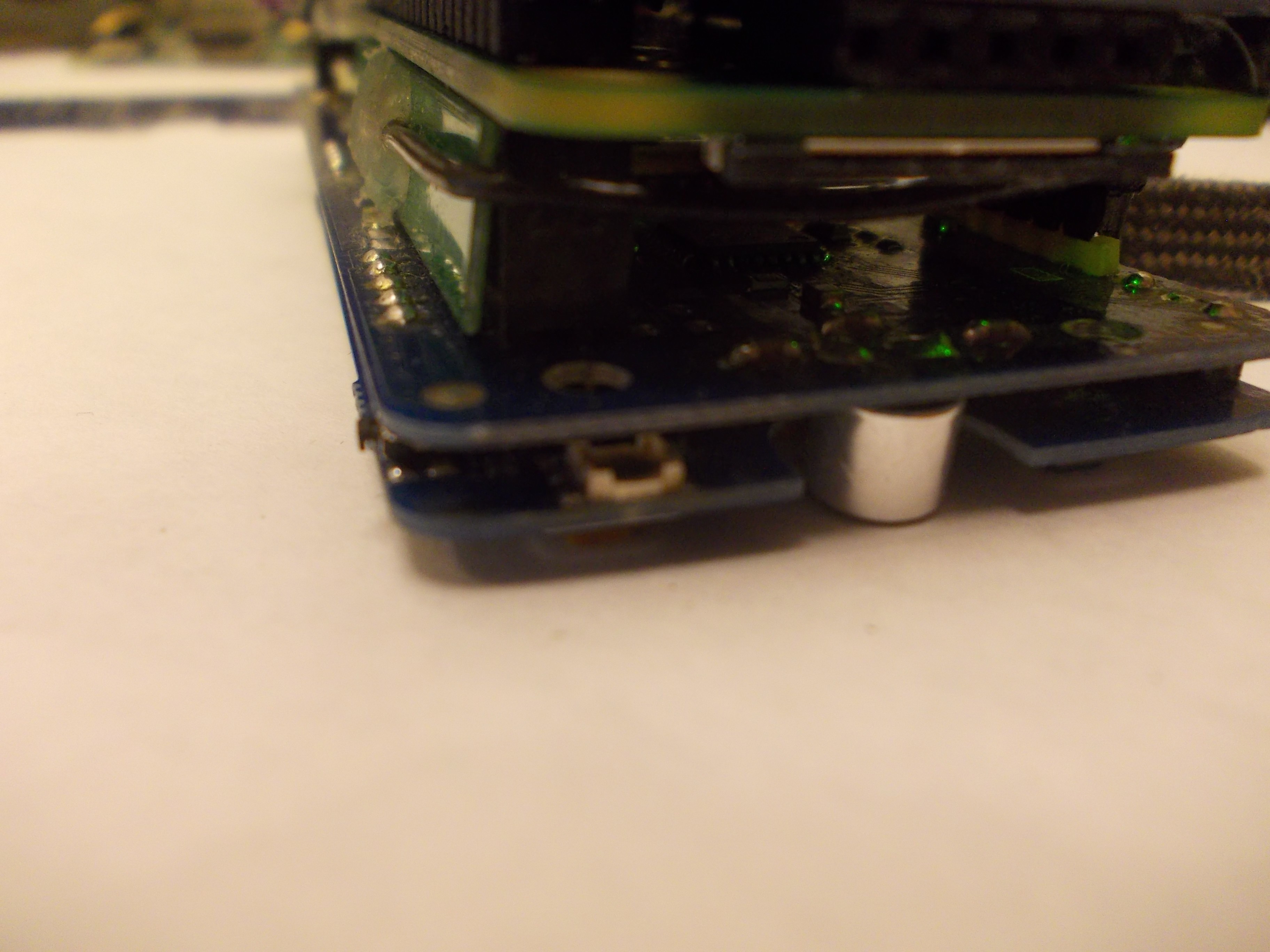
Back board capacitors
The back board has two big decoupling capacitors - near the GSM modem (VBAT) and the Pi Zero 5V pins (VSYS). They're tantalum capacitors in case D, and they're pretty thick. Since the 18650 and back boards are back-to-back, it results in the 18650 board not being flush to the back board, being at an angle. This is not neat - in particular, it makes it harder to make cases for ZeroPhone. So, the capacitors either need to be split (replacing one capacitor with multiple capacitors in parallel), or low-profile capacitors need to be used - however, low-profile capacitors are expensive. In addition, it's harder to source certain types of capacitors recently, since Apple device production seems to have created artificial scarcity - not only for the capacitors they're using, but also for other types (since most factories are overloaded with making capacitors that Apple has ordered, they have less time for other values of capacitors, which also results in scarcity and prices rising). So, they'll need to be re-thought before production. It's also necessary for us to find some kind of way to avoid fake capacitors (most likely, a reputable supplier) - the kind of capacitors that we're using is a popular target of fake component sellers.
Side buttons
ZeroPhone keypad has 5 side buttons, soldered on the bottom of the keypad board. These buttons have small plastic actuators (the parts you press on), and they stick out of the keypad board outline - as a result, they break off easily when you're carrying your ZeroPhone without a case. These buttons are also the hardest to replace - once the keypad PCB is soldered onto the front PCB, you can't really desolder the buttons easily, since the gap between front and keypad PCBs is quite small. I don't yet have an idea on avoiding it - these buttons are prone to breaking even when some kind of a case is covering them. However, a case is still in order, undoubtedly - more about that soon, in a separate blog post! ;-)
Discussions
Become a Hackaday.io Member
Create an account to leave a comment. Already have an account? Log In.
1. In regards to the pad delamination, oval pads are typically stronger because there's more surface area, yet you can retain the spacing between the pins.
2. For the Pi header, custom pin headers aren't too expensive. The biggest issue is you'll have to buy a bunch for the project and resell them instead of making the user source the parts themselves.
Are you sure? yes | no
1. Thank you, added to TODO! https://github.com/ZeroPhone/ZeroPhone-PCBs/issues/57
2. Well, if I'm making kits on a large scale, it'd make sense to order a batch of custom pin headers - saving myself from possible kit assembly problems =) For self-assembly, there's still the manual solution of "pushing the pins as far into the board as possible", which seems to work okayish.
Are you sure? yes | no
Regarding Speakers : we had a similar problem while building Kite DIY Smartphone Kit (https://hackaday.io/project/42944-kite-3d-printable-diy-modular-smartphones). We have since moved to using part number PSR1511N06S3K (ordered from DigiKey) . This speaker is easier to solder. Please check that part out. You may be able to zoom in to this image to see the soldering - https://cdn.hackaday.io/images/2633211518157418107.jpg . Our audio components are in this picture: https://cdn.hackaday.io/images/4990091518157517777.jpg .
Are you sure? yes | no
What are you plans on automating this kind of soldering?
Are you sure? yes | no
We haven't spent much time thinking about this aspect, as we don't regard this part as a final part. There are options like AS01508AO-LW25-R, which come with wires.
Are you sure? yes | no
I had some luck with speakers from this Chinese seller — they have a large choice, and the quality seems to be good: https://www.aliexpress.com/store/2781051
Are you sure? yes | no
Thank you, will look into it!
Are you sure? yes | no