This project GM-Study-Max only succeeded because I progressed through earlier prototypes GM-Proto-E1 and GM-Study-E1, before committing to the final and complex SMD design of GM-Study-Max.

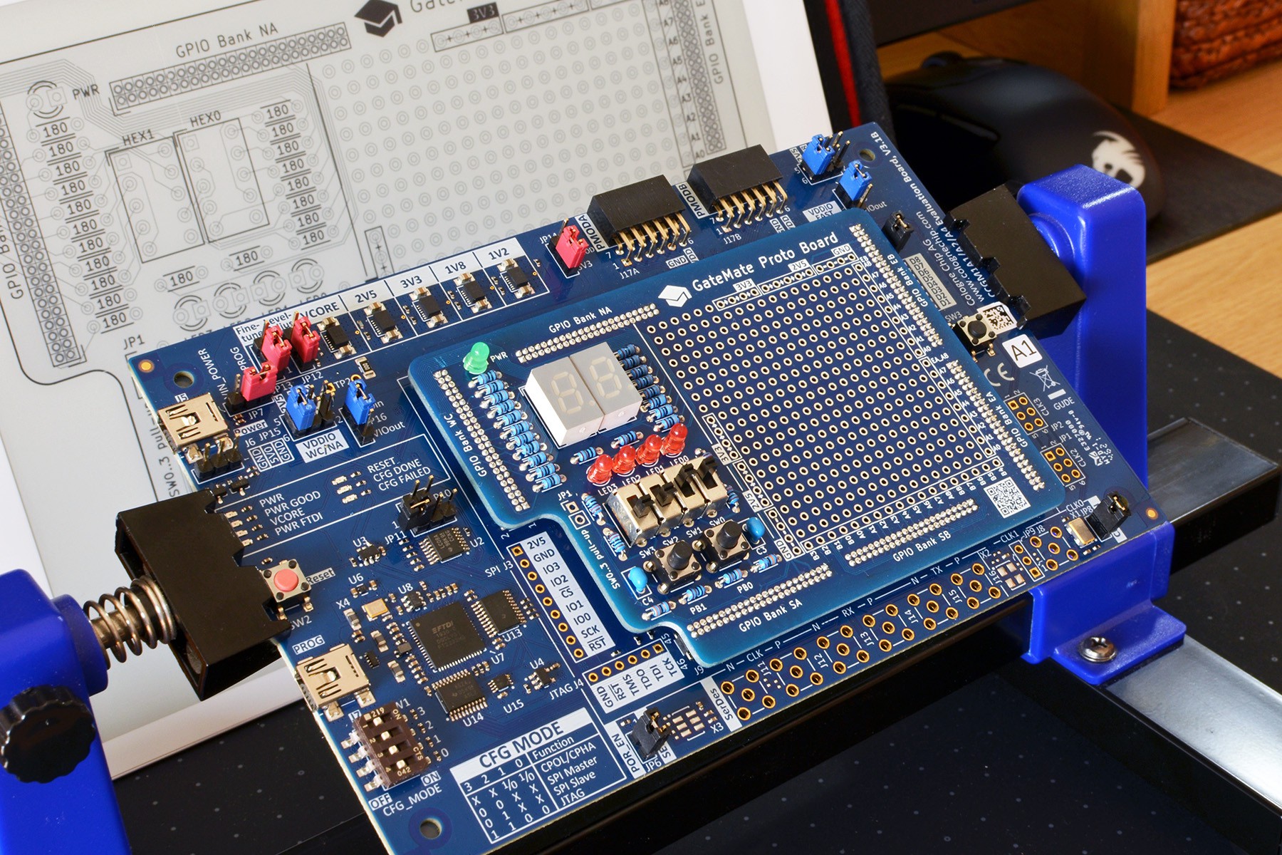
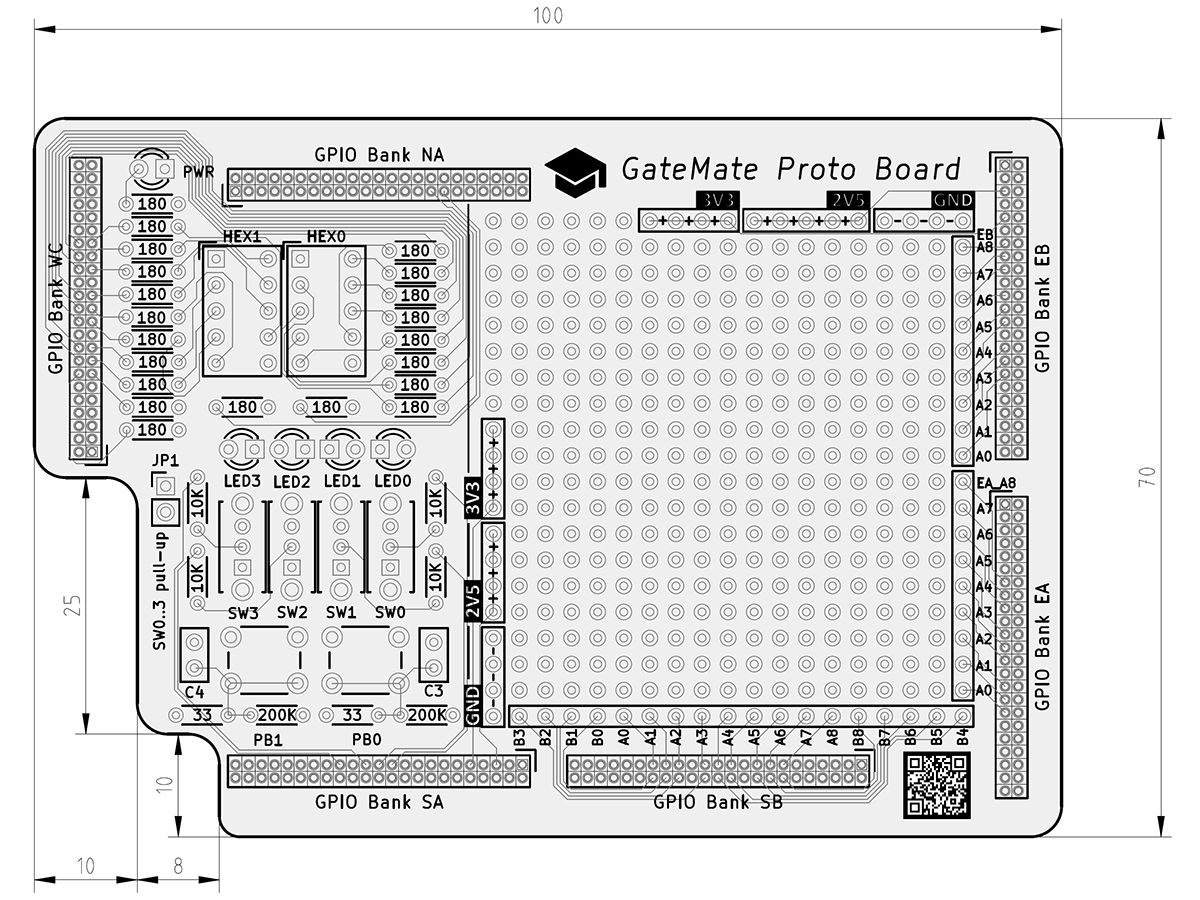
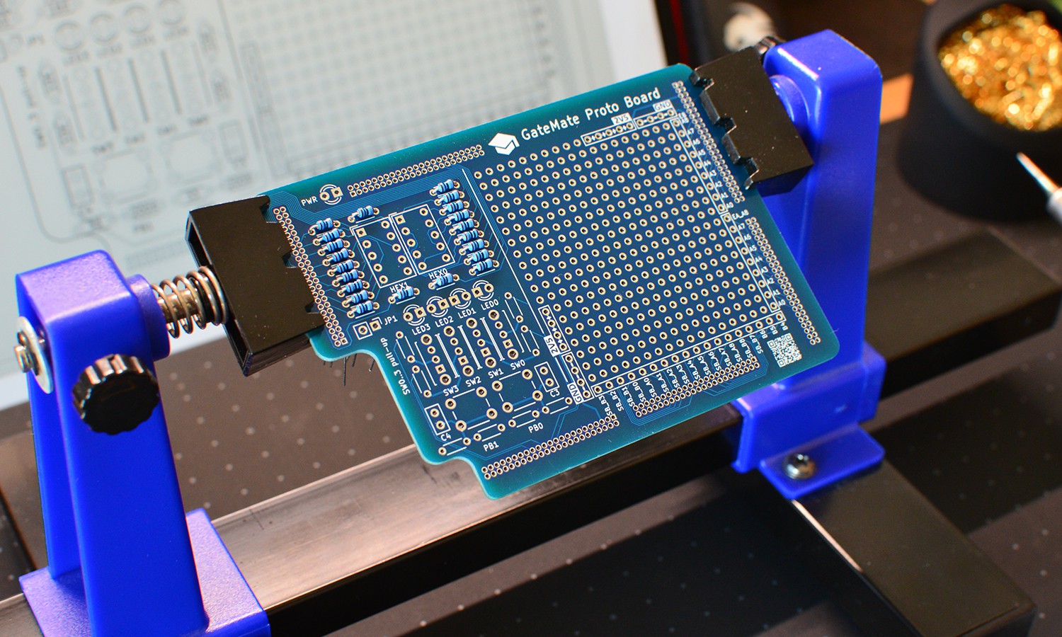
In the 1st milestone GM-Proto-E1 project, I built a much simpler daughter board, purely in through-hole technology. It achieved three goals:
- Validate the connector measurements and PCB production is sufficiently precise.
- Check if I am able to solder the 276 pins at fine 1.27mm pitch reliably.
- Get a prototype board that exposes pins in standard 2.54mm pitch for easy testing.

Because the PCB design is only using THT, a failure would not be costly since PCB manufacturing without SMD assembly has fast turnaround and is very reasonable priced. Being able to prototype with general-purpose IO THT components gives confidence for the final design before switching to surface-mount components. SMD parts are hard to test, specs are easily misread, and SMD production re-runs for mistakes increase cost and time.

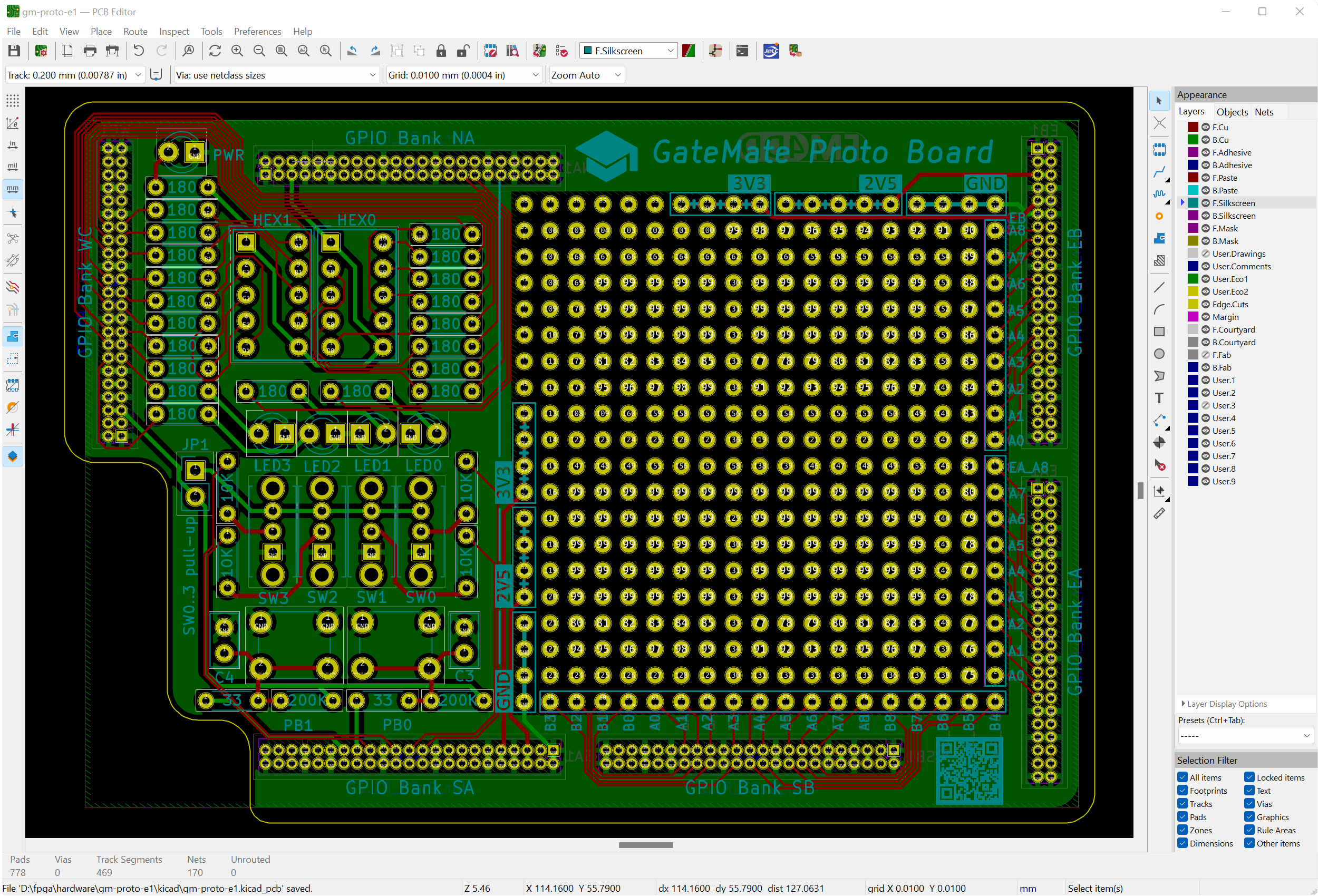
The board layout has been created in KiCAD, which is ideal for such tasks.

Finally, Verilog code verifies the basic set of onboard components: 4 LEDs, 2 buttons, 4 switches, and 2 7-Segment display modules. A demo video is available here:
 Frank
Frank
Discussions
Become a Hackaday.io Member
Create an account to leave a comment. Already have an account? Log In.