For a while I kept calling this module the 'PPE'. The pandemic has had lasting effects. If you see PPE anywhere in these logs, you know I mean PPI.
PPI means Programmable Peripheral Interface. It's part of the MSX1 spec, an i/o device. The 82C55 chip is used, it has 3 registers accessed using 3 ports and another port is for commands. The MSX uses these for keyboard scanning, RAM/ROM slot control, some of the cassette functionality and some other things such as the caps LED and generating a click for the keyboard.
This is clearly an important part of a working MSX and a module that I will need to add to the RC2014. Happily the 82C55 is still available new today (although there seem to be supply issues as I write this.)
Credit to Dino who has published a schematic for an RC2014 PPI module and sells a PPI module as part of a keyboard kit. As I've said before, the yellow-board MSX system is available but it's MSX2+ which is more advanced than the MSX1 that I want to build.
I've designed a standard RC2014 module that contains all of the functionality I need. As this is still experimental, I've left many of the connections on headers for now, including the slot select lines. I think I will decode those into 4 active-low lines (for the 4 MSX RAM/ROM 'slots') and use the 4 spare lines on the standard RC2014 bus for those, but that's a decision for another day. I've also included the wait-state generator on this board, but may take it off because I don't think I need it, even if I run at full RC2014 clock speed of 7.3 Mhz.
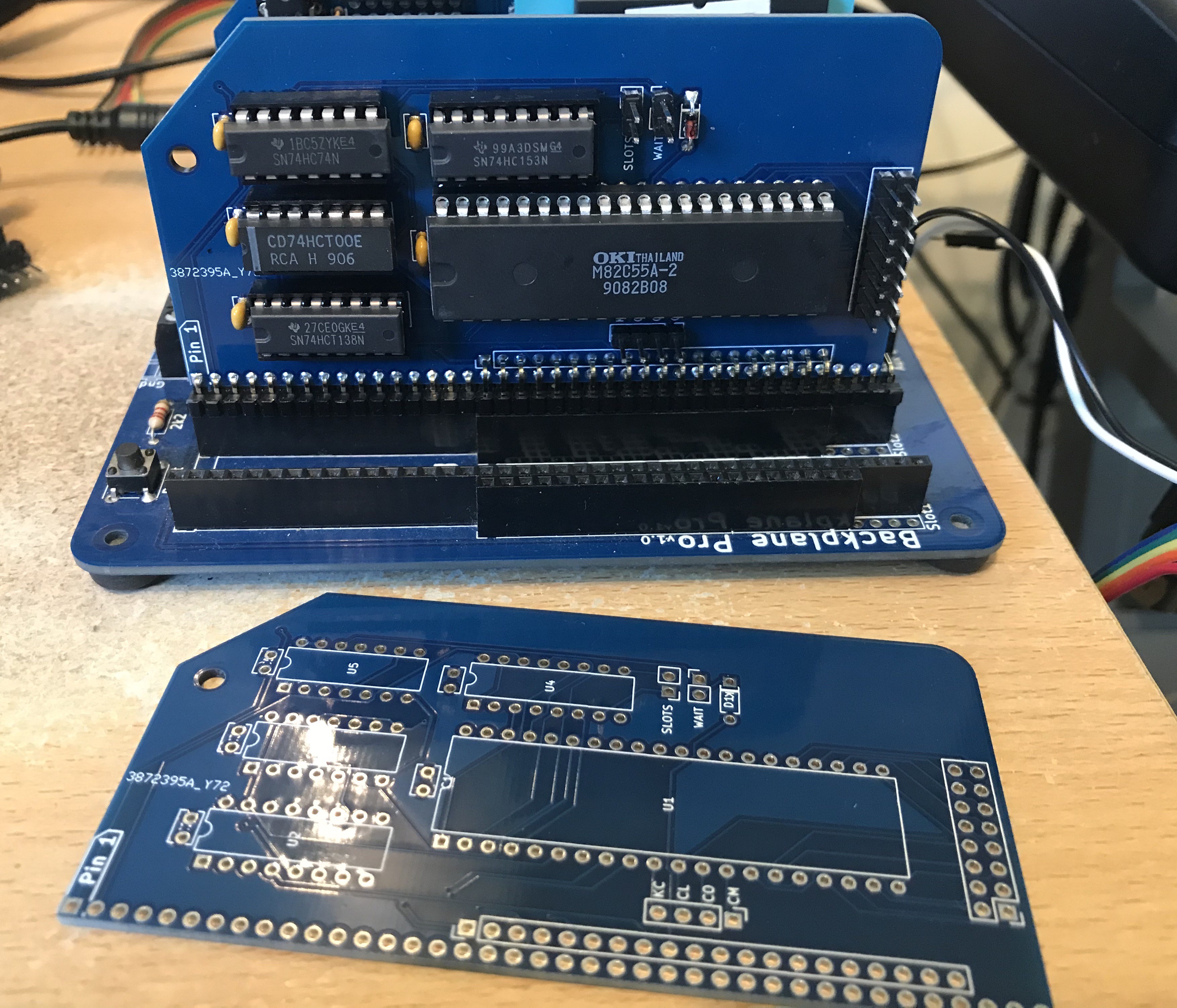
Here's the board and a built module:
Initially this didn't seem to work. But I realised that the 8255 is 'programmable' (basically the direction of the registers) and the very first thing that the MSX does on startup (as can be seen with a quick look at the source of c-bios) is an out to port $ab, $82 and an out to port $aa, $50
The first out sets the mode so that the 3 registers work in the way that we need. The second sets the state of port C. (the PPI uses four port addresses - 0xa8 -0xab. a8 is the slot control and can be written and read)
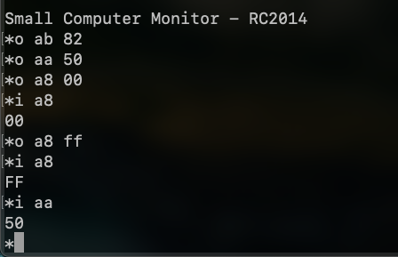
The screenshot above shows the module in my RC2014. I'm running SCM which allows you to easily read and write to the hardware ports) I can perform those two 'outs', then successfully read and write port A and read back the value written to port C.
The next step is to bodge some RC2014 RAM and ROM modules so that they can be selected using the slot select lines that this module generates.
Discussions
Become a Hackaday.io Member
Create an account to leave a comment. Already have an account? Log In.