 Jon
JonWant to get one?
If you want to get this board and its accessories, visit the product page at:

How does it work?
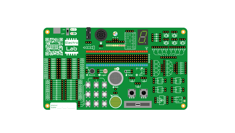
The ElectroLab board contains more than 50 different components grouped by blocks:
- 30x Resistors (9 different values)
- 20x Capacitors (10 different values)
- 4x Diodes
- 5x Transistors (3 NPN & 2 PNP)
- 8x Operational amplifiers
- 14x Logic gates (4 ANDs, 4 ORs & 6 NOT)
- 4x JK Flip Flops
- 1x Audio amplifier
- 1x 555 signal generator
- 9x pushbuttons
- 1x resistive tactile sensor
- 3x potentiometers (two rotors and one slider)
- 1x microphone
- 1x photoresistor (LDR)
- 1x thermoresistor (NTC)
- 1 triaxial accelerometer
- 1x gas sensor
- 1 nine-led bar
- 1 RGB led
- 1 7-segment display
- 1 Speaker
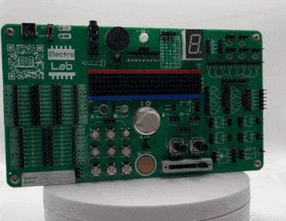
By using this set of components, you can easily build your own circuit by connecting them directly with female-female DuPont wires to the corresponding pins of each component. The only limitation to the circuits you can create is your own imagination (and the availability of cables and boards, of course :D). These components have been thoroughly tested with various circuits that are ideal for learning basic electronics, such as:
- Oscillators with transistors, resistors, and capacitors
- Circuits with Op. Amps (sum, diff, integrator, etc)
- Analog to Digital converter with Op. Amps
- Combinational circuits with logic gates
- Sequential circuits with Flip Flops
- Counters with Flip Flops
- Binary to Decimal converter
- Square signal generators with the 555
- Timer with the 555
- Politone keyboard
- Audio amplifier with low/high passes
- Volume indicator with LED bar
- Horizontal level indicator with LED bar
The story behind ElectroLab
 ElectroLab’s story goes back to 2016. By then I was finishing my engineering degree and working as content creator and course coordinator for the Technological Campus of ICAI (CTI). This summer campus takes place in Madrid during 4-6 weeks and is addressed to pre-university students in the 14-18 years old range. The courses offered on the campus are normally 1-week duration 6h/day and aim to cover the basics of a specific topic (ie: robotics with Arduino, videogame design) in a very interactive and easy-to-follow way based on praxis and experimentation.
Among the courses I used to coordinate back then, the one on Electronics felt especially interesting for me: I wanted to offer a solid basis and at the same time let my students experiment in a safe way with each newly acquired concept. But the most important was to make it fun.
I had around 8 months to come up with the contents, the workshops, and most important: the electronic platform where to experiment with the course content (sensors, electronic components, etc). Back then, my experience pushed me away from breadboards, not because they were not a good solution, but because in a class filled with more than 10 students, debugging the mistakes committed on a breadboard (bad connections, components pins damaged by extensive usage, polarity misconnections) could become unsuitable for the given time.
Since it was the first edition of the Electronics course and we were not sure if it would succeed, the possibility of acquiring expensive and heavy electronic trainers was neither an option.
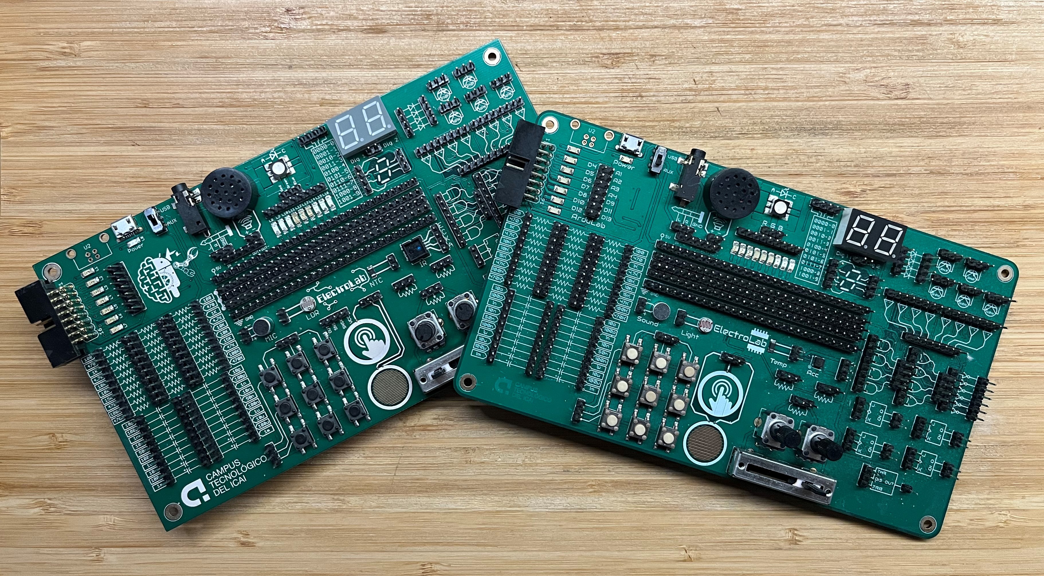
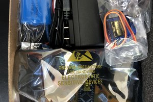
Instead, I kind of mixed both concepts in a compact, yet powerful, solution: the ElectroLab, a 175x100mm board that had on the top side the (male) pins and connectors for each component and on the bottom all the SMD components routed to each corresponding pin and ready to be used.
ElectroLab Mk. I (V1)
The very first prototype of the ElectroLab cannot be considered one of my finest jobs. Except for the simplest components, most of the ones that required some kind of circuitry preparation didn't work correctly: the op. amps were not correctly powered, the flip flops and the logic gates had no pulled-down inputs (so were reading static noise while not receiving...
Read more »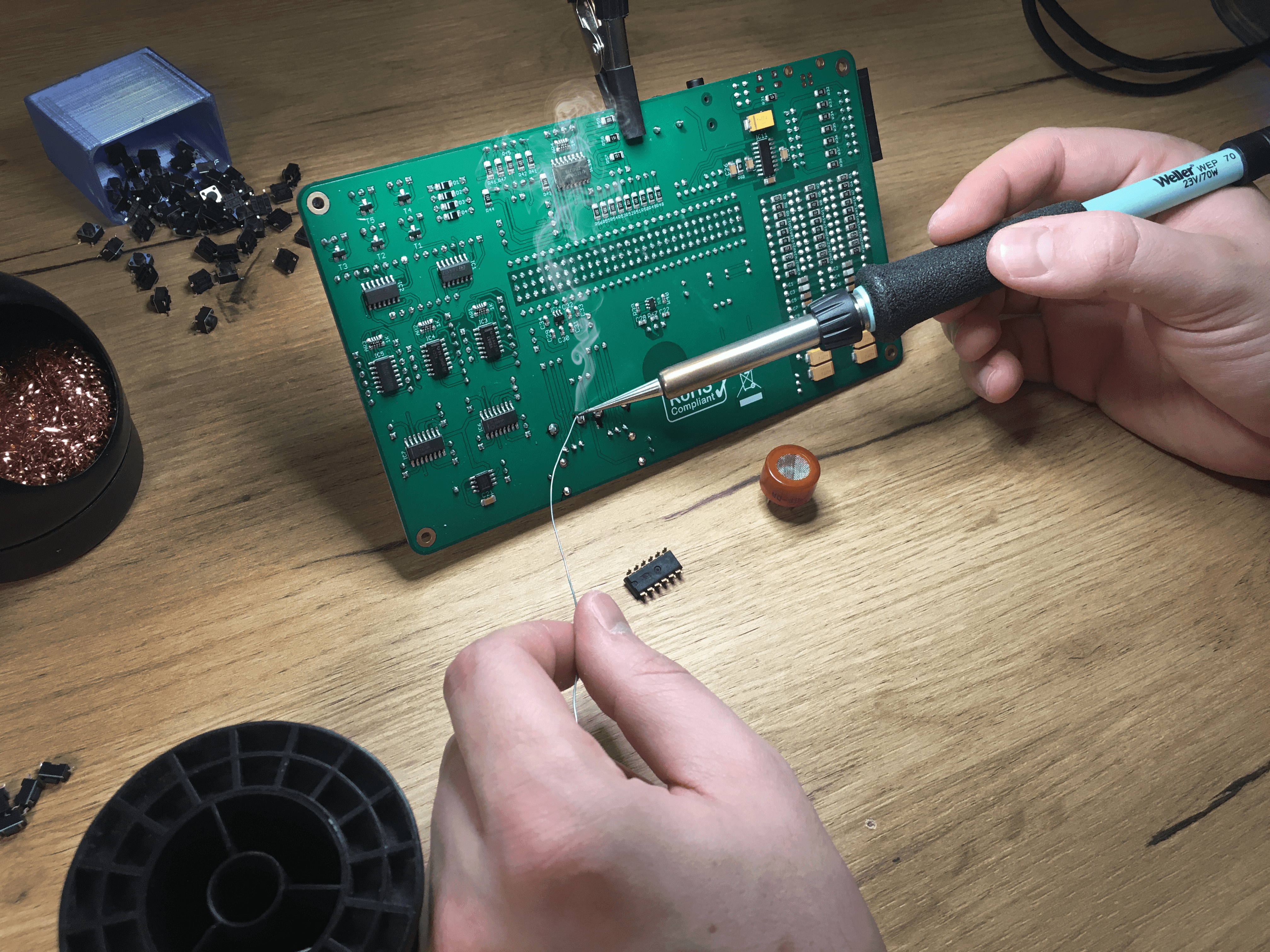
 Rodolfo
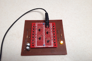
 agp.cooper
 The Big One
 drewrisinger