 CriptasticHacker
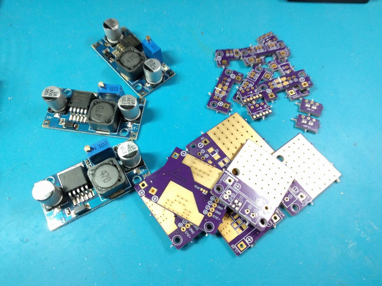
My "juggling" (as I like to call it) has been paying off. Engineering work is largely about playing a balancing act with manufacting and dev time, which I am quite used to at this point. I cranked out the most important PCBs in EagleCAD first, so I could do other things (like write these logs!) during the 2 week manufacturing lead times. Now the time to solder has arrived! :D
At the risk of being unpopular, I will add that I am always disappointed with the programmers who refuse to or are afraid to work with their hands. *gasp* what if we look blue collar?! I, on the other hand, love soldering and getting my hands dirty. It's my comfort zone and whenever I can take out the SMD tools and magnifier I am happy to do so :)
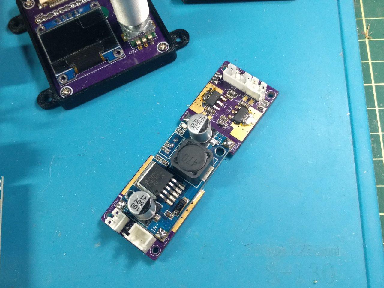
The PCB here assembled like a charm. My design worked very well, and only the trim pot resistor breakout PCB wasn't needed (because there is an 0603 pad for the rheostat on the LM2596 module - how convenient!)
The feedback network to determine output voltage from the DC-DC buck converter (LM2596) has a pre-set 270ohm resistor for the low side, and this empty pad under the trim pot for the high side.
My new add-on PCB makes a split rail supply (+5V and +3.3V) from this output. Let's try something nice for the LDO, I find +7V works well to eliminate any drop outs.
Saving time with this nice little write-up, I decided on 1K3 for the rheostat since:
Vref = 1.23( (R2/R1) +1)
where R2 = 1K3 and R1 = 270ohms.
This gives us ~7.15V output. A reliable 2.15V over to make sure there isn't any drop out.
and it works great so far :)
But what's that you say? It's naked? Exposed! *shrieks* the emperor has no clothes! I guess it's time to..
-- 3D ENCLOSURE MODEL --
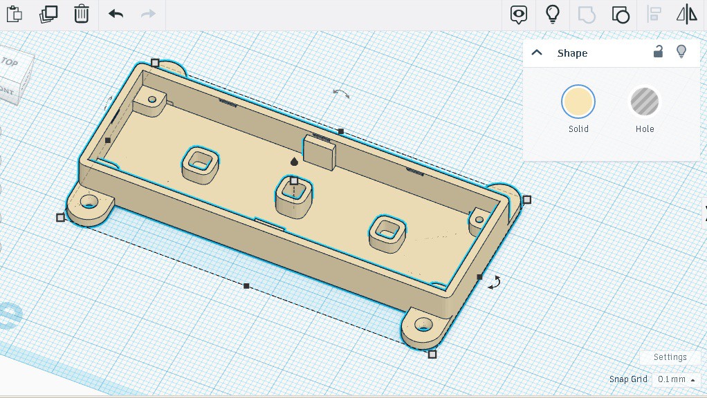
I whipped this up in an hour to protecc the bottom of our new triple PCB combo, as well as help with alignment. It utilizes countersunk M2*5mm screws and sports a couple other nice additions. It has:
- counter sunk external mounts
- 3 different height standoffs to support the PCBs
- indentations in the middle for LM2596 alignment, and
- locking divets for a future lid design
Not too shabby. So how did the first print turn out?
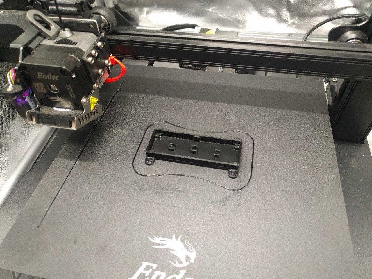
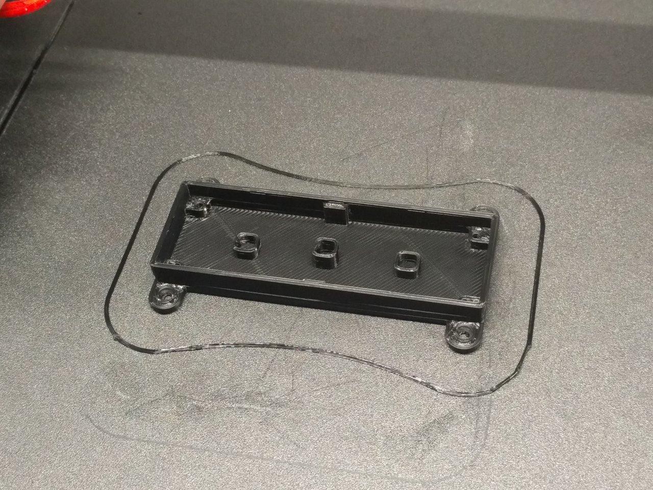
Looks like the Ender 3 S1 Pro is doing a good job! I went for the magnetic build plate because I get tired of occasional adhesion issues with PEI. For a one-off print, these work pretty well. If you're wondering, I'm using Polymaker black PLA with all standard settings. Of course, gotta dial in those expand settings in Cura for dimensional accuracy too.
And did it fit...?
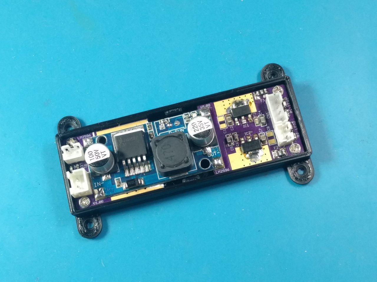
Beautifully :) Might add 0.25mm on the LM2596 indents, but what's here is wonderful (1 hr 12 minutes print time @ 50mm/s speed). ^_^
[to be continued...]
Discussions
Become a Hackaday.io Member
Create an account to leave a comment. Already have an account? Log In.