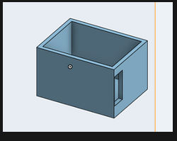
5Week 4 summary: Another version of the code was created, allowing for more changes in color in the color spectrum. After that was debugged and all the colors showed up, as well as all of the variables functioning properly, the code was modified to change colors faster through the encoder readings. The rate at which the colors changed was increased, making the process from shifting one color to another, easier. A new cad was also developed to allow for the charge of the battery and the uploading of code, while also allowing all of the internals to fit into the encapsulation.
After all of the parts arrived we quickly realized that the original CAD for the watch wouldn't be able to hold the internals of the watch because the measurements were off. We also haven't incorporated gaps in the CAD of the shell of the watch to allow for charging the watch and uploading code to it. Taking all of those pieces into consideration. A rough outline for how the internals would be stacked on top of each other was made and measured producing out final CAD of the externals of the watch.

Version 2 of the code to change the color of the LED based on the position of the dial.
We used a variable that counts how many ticks the rotary encoder has turned and in which direction. We took the variable and called it counter and inserted it into the LED light to display the RBG value that dictates the color that's going to show. Nupur made a function for when the dial gets turned it makes another variable go down/up depending on the encoder readings. In order to make the LED change colors faster with fewer dial rotations, we multiplied the counter value by 10.
/*
 * This example shows how to read from a seesaw encoder module.
 * The available encoder API is:
 *      int32_t getEncoderPosition();
        int32_t getEncoderDelta();
        void enableEncoderInterrupt();
        void disableEncoderInterrupt();
        void setEncoderPosition(int32_t pos);
 */
#include "Adafruit_seesaw.h"
#include <seesaw_neopixel.h>

#define SS_SWITCH        24
#define SS_NEOPIX        6

#define SEESAW_ADDR          0x36

Adafruit_seesaw ss;
seesaw_NeoPixel sspixel = seesaw_NeoPixel(1, SS_NEOPIX, NEO_GRB + NEO_KHZ800);

int32_t encoder_position;

void setup() {
  Serial.begin(115200);
  while (!Serial) delay(10);

  Serial.println("Looking for seesaw!");

  if (! ss.begin(SEESAW_ADDR) || ! sspixel.begin(SEESAW_ADDR)) {
    Serial.println("Couldn't find seesaw on default address");
    while(1) delay(10);
  }
  Serial.println("seesaw started");

  uint32_t version = ((ss.getVersion() >> 16) & 0xFFFF);
  if (version  != 4991){
    Serial.print("Wrong firmware loaded? ");
    Serial.println(version);
    while(1) delay(10);
  }
  Serial.println("Found Product 4991");

  // set not so bright!
  sspixel.setBrightness(20);
  sspixel.show();

  // use a pin for the built in encoder switch
  ss.pinMode(SS_SWITCH, INPUT_PULLUP);

  // get starting position
  encoder_position = ss.getEncoderPosition();

  Serial.println("Turning on interrupts");
  delay(10);
  ss.setGPIOInterrupts((uint32_t)1 << SS_SWITCH, 1);
  ss.enableEncoderInterrupt();
}

void loop() {
  if (! ss.digitalRead(SS_SWITCH)) {
    Serial.println("Button pressed!");
  }

  int32_t new_position = ss.getEncoderPosition();
  // did we move arounde?
  if (encoder_position != new_position) {
    Serial.println(new_position);         // display new position

    // change the neopixel color
    sspixel.setPixelColor(0, Wheel(new_position & 0xFF));
    sspixel.show();
    encoder_position = new_position;      // and save for next round
  }

  // don't overwhelm serial port
  delay(10);
}


uint32_t Wheel(byte WheelPos) {
  WheelPos = 255 - WheelPos;
  if (WheelPos < 85) {
    return sspixel.Color(255 - WheelPos * 3, 0, WheelPos * 3);
  }
  if (WheelPos < 170) {
    WheelPos -= 85;
    return sspixel.Color(0, WheelPos * 3, 255 - WheelPos * 3);
  }
  WheelPos -= 170;
  return sspixel.Color(WheelPos * 3, 255 - WheelPos * 3, 3);
}
This revised code of version 2 allows the color to change more frequently with fewer turns of the dial.
if ((multiplier > 0) && ( multiplier < 255)) {
        rgbA = 255;
        rgbB = multiplier;
        rgbC = 0;
      }
            //yellow to green
      if  (( multiplier > 255) && (multiplier < 510 )) {
        rgbA = helper2;
        helper = multiplier - 255;
        helper2 = 0 - helper;
        rgbB = 255;
        rgbC = 0;
      }

      //green to blue
      if ( (multiplier > 510) && ( multiplier < 765 )) {
        rgbA = 0;
        rgbB = 255;
        rgbC = multiplier - 510;
      }
            //blue to dark blue
      if  (( multiplier > 765 ) && (multiplier < 1020 )) {
                helper3 = multiplier - 765;
        helper4 = 0 - helper3;
                rgbA = 0;
        rgbB = helper4;
        rgbC = 255;
      }

      if ( (multiplier > 1020) && ( multiplier < 1275 )) {
        rgbA = multiplier - 1020;
This is the full code that was shortened and made more efficient using improvements from the last 2 snippets. We switched rotary encoders. The way it gets the encoder position is also a different system from version 1, we used a tutorial for this part. ( https://learn.adafruit.com/adafruit-i2c-qt-rotary-encoder/arduino )
uint32_t Wheel(byte WheelPos) {
  WheelPos = 255 - WheelPos;
  if (WheelPos < 85) {
    return sspixel.Color(255 - WheelPos * 3, 0, WheelPos * 3);
  }
  if (WheelPos < 170) {
    WheelPos -= 85;
    return sspixel.Color(0, WheelPos * 3, 255 - WheelPos * 3);
  }
  WheelPos -= 170;
  return sspixel.Color(WheelPos * 3, 255 - WheelPos * 3, 3);
}
Discussions
Become a Hackaday.io Member
Create an account to leave a comment. Already have an account? Log In.