 JP Gleyzes
Configuring the FDRS network is a fairly easy operation. We have just to tell the library how the routing of messages should be done.
To do so we just have to open the fdrs_gateway_config.h file for each GTW and modify the predefined values in accordance with the choosen topology of the network.
In our case we have 3 gateways to configure.
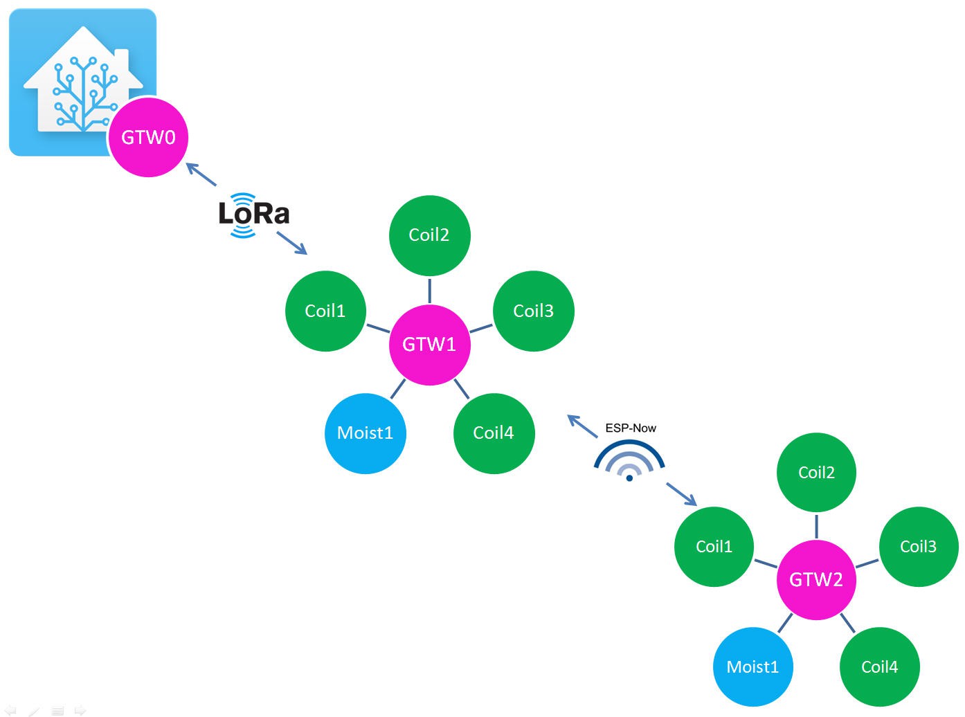
GTW2 configuration
We will start by the easiest one GTW2. It is only linked to one neighbor GTW1 via ESPnow protocol.
We can write the following configuration into the .h file
//Addresses
#define UNIT_MAC           0x02  // The address of this gateway

#define ESPNOW_NEIGHBOR_1  0x01  // Address of ESP-NOW neighbor #1
#define ESPNOW_NEIGHBOR_2  0x99  // Address of ESP-NOW neighbor #2
//#define LORA_NEIGHBOR_1  0x99  // Address of LoRa neighbor #1
//#define LORA_NEIGHBOR_2  0x99  // Address of LoRa neighbor #2

// Interfaces
#define USE_ESPNOW
#define USE_LR      // Use ESP-NOW LR mode (ESP32 only)
//#define USE_LORA
Doing this we tell the library that
- our GTW has the MAC address 2. It is indeed GTW2
- its first neighbor is ESPNOW_NEIGHBOR_1 with the MAC Address 1 --> GTW1
- its second neighbor via ESPnow does not really exist, it has a dummy MAC address of 99
- it does not have Lora neighbors (commented two lines)
Then we tell that this GTW only uses ESPNow protocol and must be configured with the Long Range option
And that's all for the network configuration.
Now we must choose the routing actions to be performed by FDRS. It's also a matter of configuration.
// Routing
// Options: sendESPNowNbr(1 or 2); sendESPNowPeers(); sendLoRaNbr(1 or 2); broadcastLoRa(); sendSerial(); sendMQTT();
//for sendSerial();  you should type values in JSON format:  [{ id: 1, type: 6, data: 384 }] or array [{ id: 1, type: 6, data: 384 },{ id: 2, type: 6, data: 385 }]and ckick send in serial monitor
//#define ESPNOWG_ACT
//#define LORAG_ACT
//#define SERIAL_ACT
//#define MQTT_ACT
#define INTERNAL_ACT   sendESPNowNbr(1);
//#define ESPNOW1_ACT    sendSerial();
//#define ESPNOW2_ACT
//#define LORA1_ACT
//#define LORA2_ACT
Among the long list of options available (have a look at the FDRS documentation ) I simply selected that I want to route the messages internally posted by the gateway via ESPNow protocol and to send the message to the first neighbor (which is GTW1).
Remember that an INTERNAL_ACT is triggered when using LoadFDRS() and SendFDRS() functions into the code.
loadFDRS(M1, SOIL_T, id); //will send back these data readings using INTERNAL_ACT event. Id 0x200 = GTW2 sensor0
sendFDRS();
We have finished with GTW2. Let's do the same with GTW1
GTW1 configuration
GTW1 is a little more complex to configur than GTW2 as it is linked to GTW0 and GTW2 respectively via Lora and ESPNow.
However the same logic apply. You only have to change a few prameters into the fdrs_gateway_config.h file
//  GATEWAY CONFIGURATION

//Addresses
#define UNIT_MAC           0x01  // The address of this gateway

#define ESPNOW_NEIGHBOR_1  0x02  // Address of ESP-NOW neighbor #1
#define ESPNOW_NEIGHBOR_2  0x99  // Address of ESP-NOW neighbor #2
#define LORA_NEIGHBOR_1    0x00  // Address of LoRa neighbor #1
#define LORA_NEIGHBOR_2    0x99  // Address of LoRa neighbor #2
Doing this we tell the library that
- our GTW has the MAC address 1. It is indeed GTW1
- its first neighbor is ESPNOW_NEIGHBOR_1 with the MAC Address 2--> GTW2
- its second neighbor via ESPnow does not really exist, it has a dummy MAC address of 99
- its first Lora neighbor is LORA_NEIGHBOR_1 with the MAC Address 0--> GTW0
- its second Lora neighbor does not exist, it has a dummy MAC address of 99
Now we will describe its interfaces and routing options
// Interfaces
#define USE_ESPNOW
#define USE_LORA

// Routing
// Options: sendESPNowNbr(1 or 2); sendESPNow(0xNN); sendESPNowPeers(); sendLoRaNbr(1 or 2); broadcastLoRa(); sendSerial(); sendMQTT();
//sendSerial() example type:  [{ id: 1, type: 6, data: 384 }] or array [{ id: 1, type: 6, data: 384 },{ id: 2, type: 6, data: 385 }]and ckick send in serial monitor
#define ESPNOWG_ACT
#define LORAG_ACT
#define SERIAL_ACT
#define MQTT_ACT
#define INTERNAL_ACT   sendLoRaNbr(1);    //when packet is entered internally (loadFDSR(), sendFDRS())
#define ESPNOW1_ACT    sendLoRaNbr(1);     //when packet comes from ESPnow1 Neighbor
#define ESPNOW2_ACT
#define LORA1_ACT      sendESPNowNbr(1);  //when packet comes from Lora1 Neighbor
#define LORA2_ACT
- So GTW1 is using both Lora and ESPNow interfaces
- when entering values from our arduino sketch we trigger INTERNAL_ACT action which will send the message to Lora neighbor1 that is GTW0. The message is thus going "upstream".
- when a message is arriving from Lora neighbor 1 (GTW0) it triggers the LORA1_ACT action which will route the message to ESPNowNeighbor1 (GTW2)? The message is going "downstream".
- When a message is arriving from ESPnow neighbor1 (GTW2) it is routed to Lora Neighbor1 (GTW0). This message will also go upstream.
And that's it !
Of course, as you are using a lora module you must describe its pins in the ESP32 board. Here it is for our Rezodo board.
// LoRa Configuration
// LoRa Configuration for REZODO purple board
#define RADIOLIB_MODULE RFM95
#define LORA_SS 27
#define LORA_RST 14
#define LORA_DIO 12
#define LORA_BUSY -1
//#define USE_SX126X


#define CUSTOM_SPI
#define LORA_SPI_SCK 26
#define LORA_SPI_MISO 35
#define LORA_SPI_MOSI 25
We have finished with GTW1. Let's do the same with GTW0
GTW0 configuration
And finally we must configure our master gateway GTW0.
This one is linked only to GTW1 on downstream side and will be connected to internet via MQTT protocoll.
Thus its configuration becomes
//Addresses
#define UNIT_MAC           0x00  // The address of this gateway

//#define ESPNOW_NEIGHBOR_1  0x99  // Address of ESP-NOW neighbor #1
//#define ESPNOW_NEIGHBOR_2  0x99  // Address of ESP-NOW neighbor #2
#define LORA_NEIGHBOR_1    0x01  // Address of LoRa neighbor #1
#define LORA_NEIGHBOR_2 0x99 // Address of LoRa neighbor #2- our GTW has the MAC address 0. It is indeed GTW0
- ESPnow negihbors are not used, they havz a dummy MAC address of 99
- its first Lora neighbor is LORA_NEIGHBOR_1 with the MAC Address 1--> GTW1
- its second Lora neighbor does not exist, it has a dummy MAC address of 99
Now we will describe its interfaces and routing options
// Interfaces
//#define USE_ESPNOW
#define USE_LORA
#define USE_MQTT


// Routing
// Options: sendESPNowNbr(1 or 2); sendESPNow(0xNN); sendESPNowPeers(); sendLoRaNbr(1 or 2); broadcastLoRa(); sendSerial(); sendMQTT();
#define ESPNOWG_ACT
#define LORAG_ACT
#define SERIAL_ACT
#define MQTT_ACT        sendLoRaNbr(1);
#define INTERNAL_ACT    sendLoRaNbr(1);
#define ESPNOW1_ACT
#define ESPNOW2_ACT
#define LORA1_ACT
#define LORA2_ACT
Quite simple as only MQTT_ACT will route the message to GTW1 and same thing for messages entered internally with INTERNAL_ACT.
Finally we must configure Lora pins as for GTW1.
And we must also setup our MQTT configuration
// MQTT Credentials  -- These will override the global settings

#define MQTT_ADDR   "192.168.0.48" //homeassistant.local
#define MQTT_PORT   1883 // Default MQTT port is 1883
#define MQTT_AUTH   //Enable MQTT authentication
#define MQTT_USER   "MQTT_access"
#define MQTT_PASS   "JP"
But this will be explained later!
This was a "complex" post but needed to understand the easy logics of FDRS library.
Our Rezodo network is ready now to be tested... but we need still to install our home automation platform!
Discussions
Become a Hackaday.io Member
Create an account to leave a comment. Already have an account? Log In.