I was asked to develop a circuit to help measure spark plug wear; and luckily, there is a direct correlation between coil energy and spark gap. The testing was going to fire the plug once every 3 seconds 24 hours a day for a year. To avoid terabytes of data, I needed a method to combine several test points and then clear the system out for the next cycle. After some analysis, it was clear that the peak energy (seen at the peak voltage point) represented the data that was needed and since I only needed the data across a bunch of sample points, it was clear a peak detector was the answer. The one addition was I needed a way to reset the peak detector after the voltage was sampled. I started simple with the typical diode and capacitor, to no avail. Then started with one op amp, which was an improvement, but nowhere near precise enough. I ended up with a design that took an input filter (LC from Murata), 3 op amps, a resistor and an opto-transistor; along with the original diode and capacitor.
Looking at the schematic, the input, which comes from a high voltage stepdown probe, is fed into a EMI filter. The signal is then fed into a voltage follower op amp. This first stage is used as a high impedance input buffer to avoid loading the high voltage probe. The output of the input buffer is fed into a peak detector with some unique features. IC3 is the initial op amp of the detector and is configured as a voltage follower, however, the feedback comes all the way from the final drive stage. When the positive input is fed with a voltage higher than the current value in the capacitor, the output goes high and starts to charge the holding capacitor. Given the noisy environment if discharging ~50kV repeatedly, I added a 1.2k resistor to eliminate spurious spikes. Since the voltage across the capacitor can't change instantaneously, the noise doesn't have an impact on the signal. In addition to noise suppression, it helps to reduce any stray current leakage through the diode. IC4 provides two functions, the one is a voltage follow output to drive the test equipment, and the other is to feed that signal all the way back to the negative input of IC3. By feeding the output back, a precise representation of the peak voltage is retained.
The last part of the circuit is IC5, which is an opto-isolated transistor used to reset the peak voltage. As described above, the requirement was to find the peak voltage across dozens of spark events. After a prescribed number of events, the output data is sampled and the led of the isolated transistor is turned on to short out the capacitor and reset the circuit for the next set of events.
 Floydfish
 Electroniclovers123
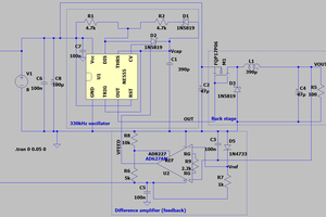
 Vedran