I wanted to buy as few things as necessary for this project. This turned out to be
- Transparent PLA
- 2 perf boards (proto boards? whatever the correct name is)
- 15x 4 OpAmps
- a bunch of wire
The project started when the contest was announced. I only recently discovered the podcast (and the rest of the community) and got a fire lit under my but.
The first thing i did was print out the bread board. the first one had walls that were too thick so did it again with one layer walls, floor and roof. I cannibalized the metal insides from an existing breadboard.

at first i wanted to use a micro controller but couldnt figure out how to get 60 adc readings.
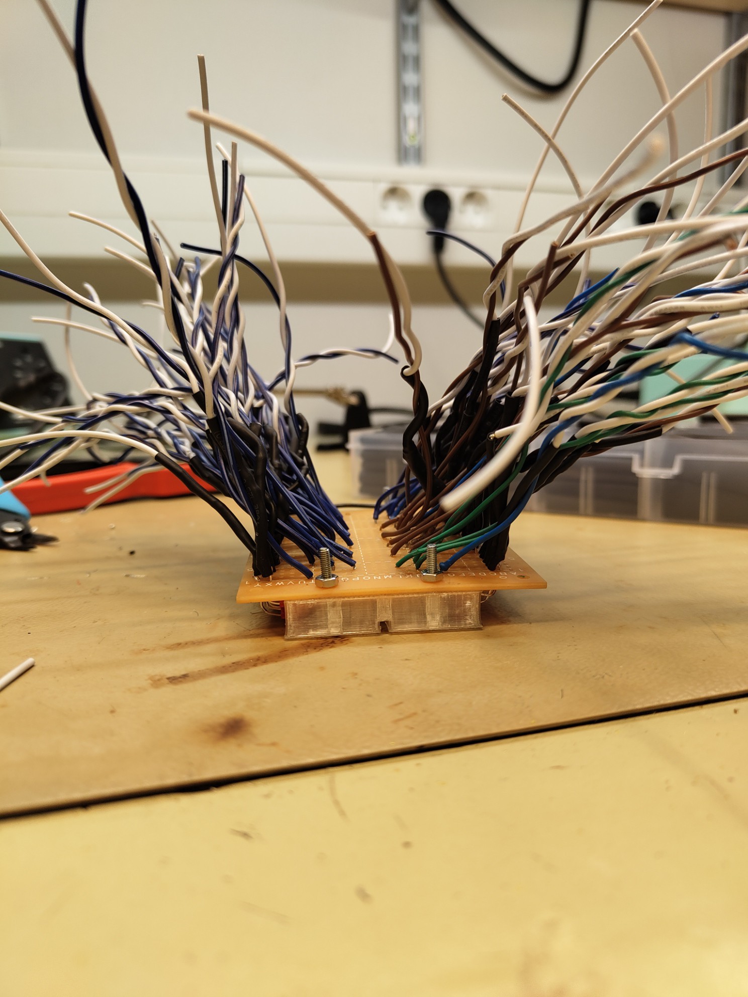
The opamps are to make sure the activity on the board isn't bothered by the lights. Opamps were purchased and soldered onto a perfboard with ones next to each other fliped so that the Vin and "ground" pins could be connected more easily. The + input of an opamp would become the signal input and the output was connected to the - pin and would in future connect to an LED. Somehow.

Connecting power was pretty easy. Though some hot glue needed to be used in a case of melted isolation.
The following took place over the last 2-3 days.
electrical sigval from the bradboard acieved by soldering a wire to the perfboard and making the dot of solder touch a line. this was unreliable. Alternative plan. solver a full line for each signal and sand them down to be level with each other. this works better. Now the breadboard is attached to a perfboad.

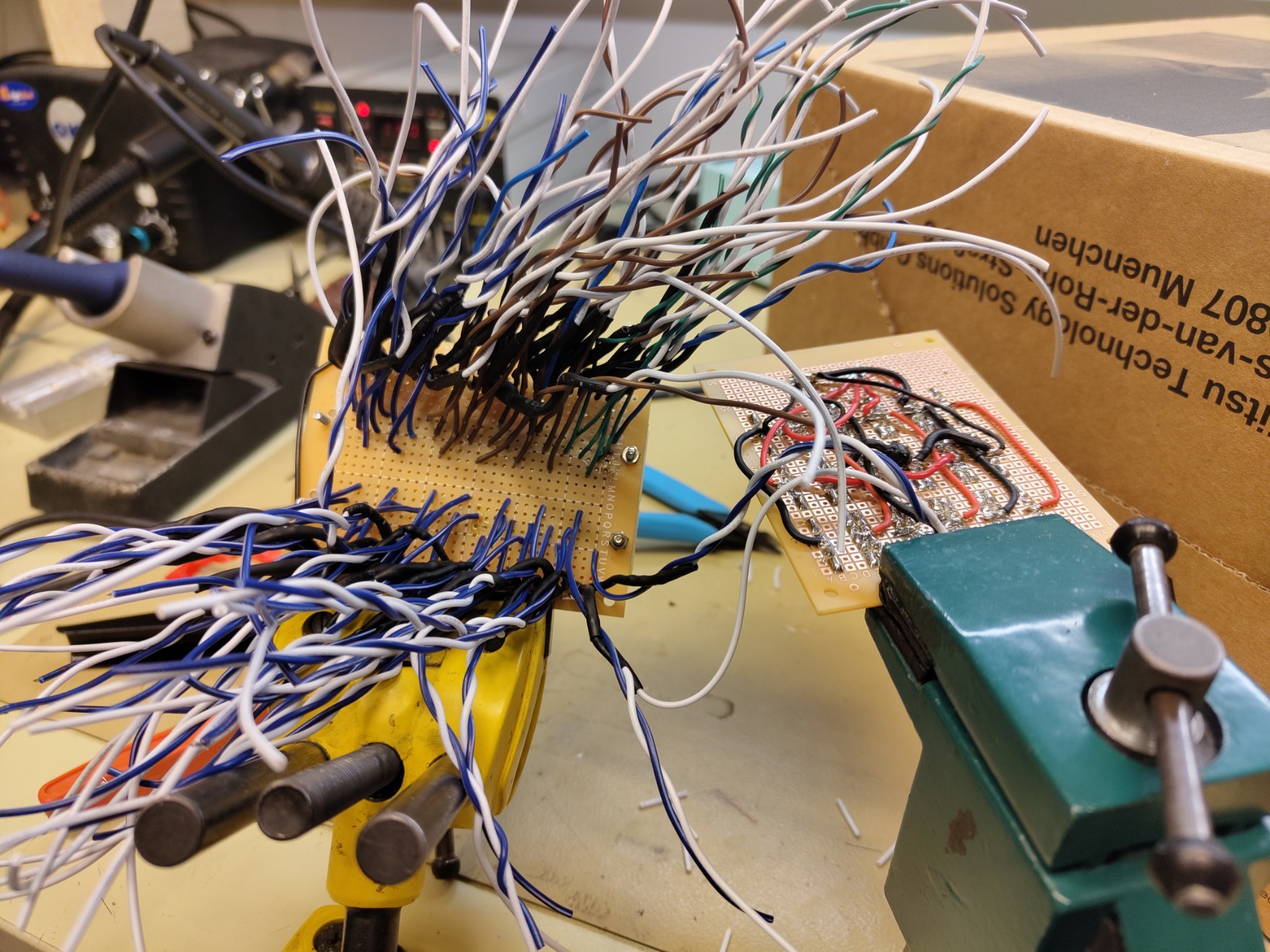
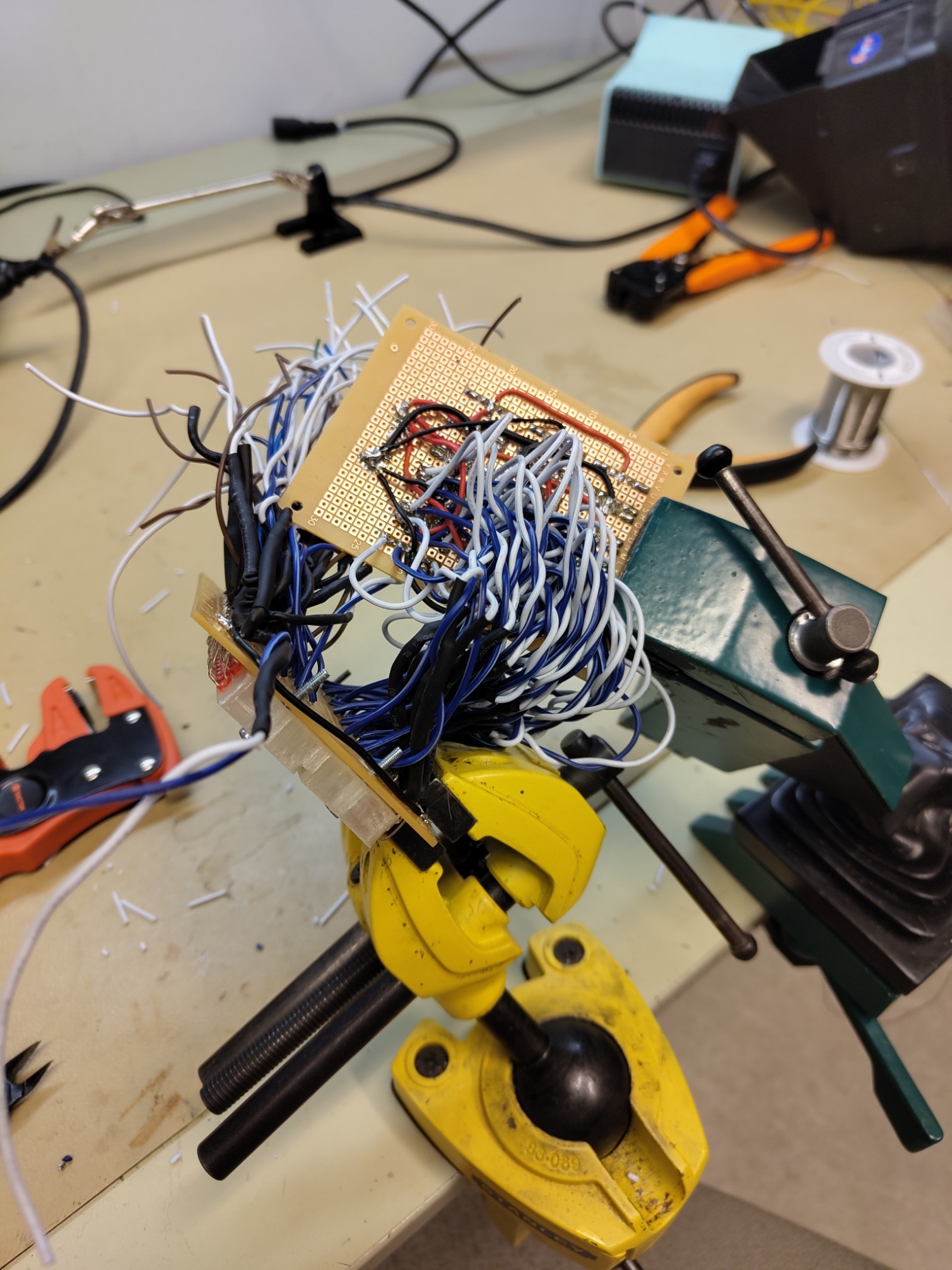
solder in a battery connector and connect the ground between the LEDs and the OpAmps. some wires have fallen out but at this point your happy as long as the lights turn on
realize you didn't test ANYTHING before.
Test using 5V on power supply.
It doesn't work. In fact it reaches the current limit. none of the leds are on.
realize you messed up on the V+ and V- on the opamps.
quick fix.
test again. lights turn on
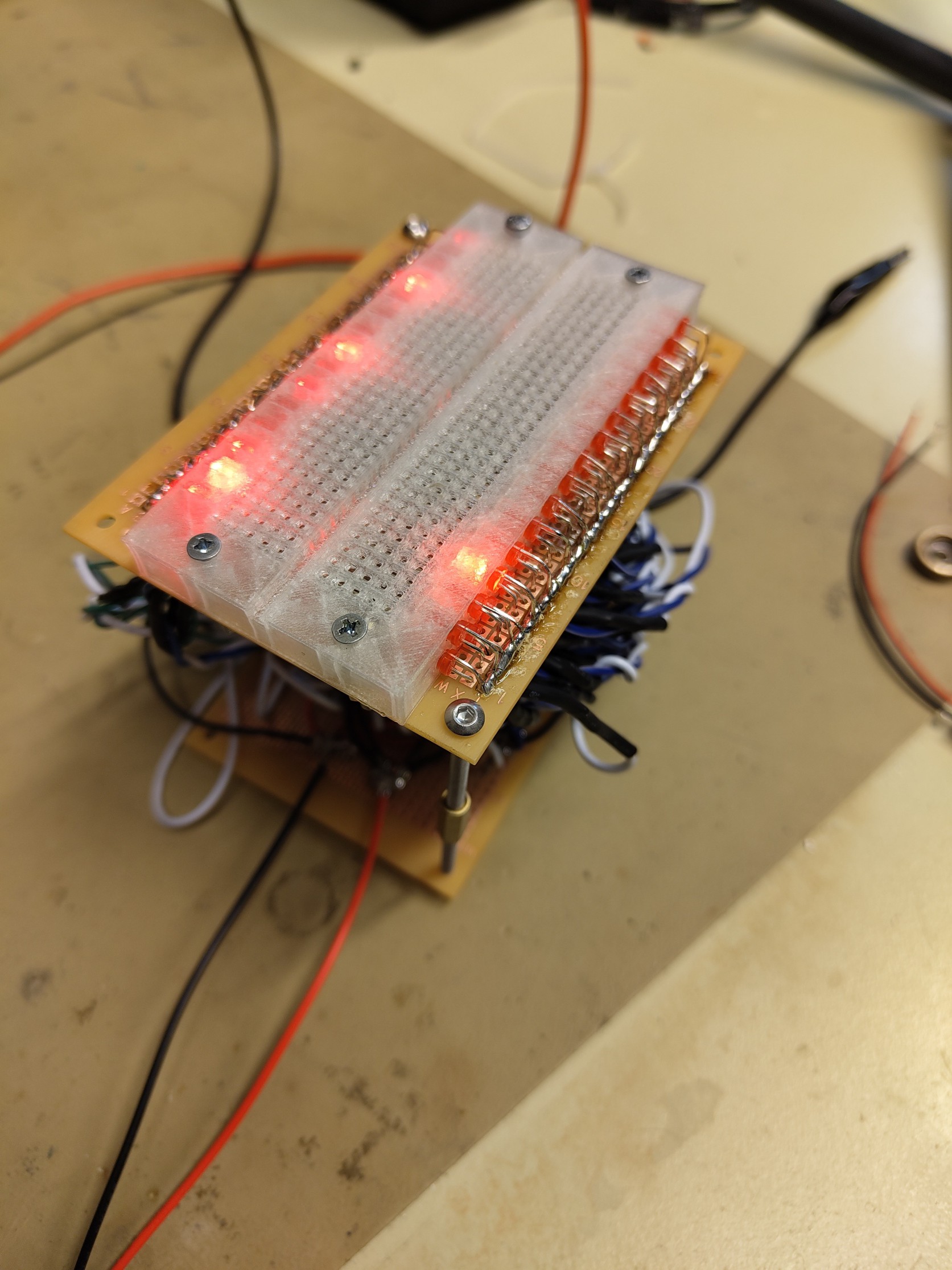
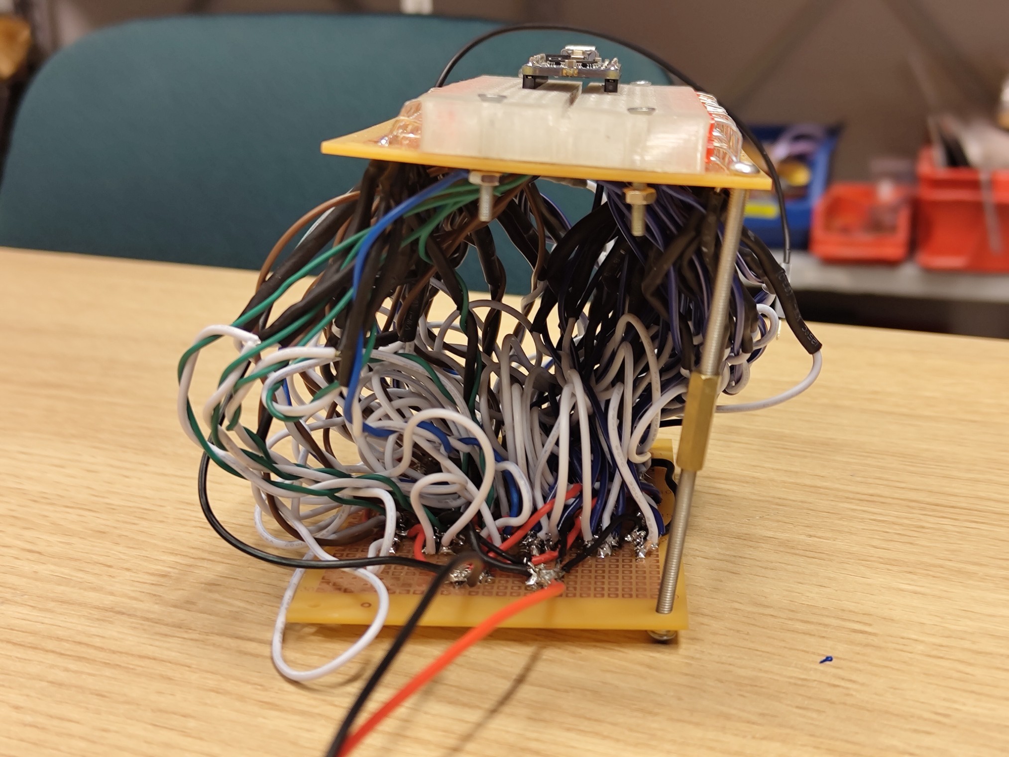
celebrate and show off the rats nest to the world
For the future
For V2 alllll this stuff will move onto a PCB
Discussions
Become a Hackaday.io Member
Create an account to leave a comment. Already have an account? Log In.