I heard about the ESP-NOW wireless protocol a while ago and I thought a custom controller would make a good addition to this project. This will not be included in the original budget of $10, but it will still be very cheap to make at around $5, and much cheaper than buying a PlayStation (or other) controller.
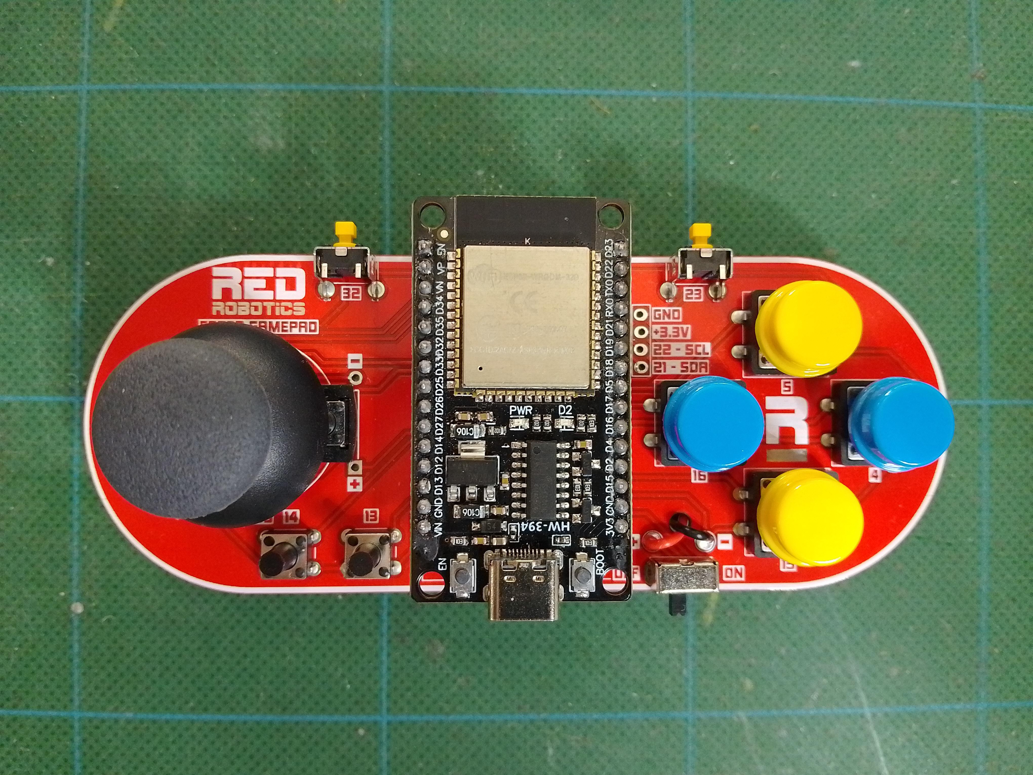
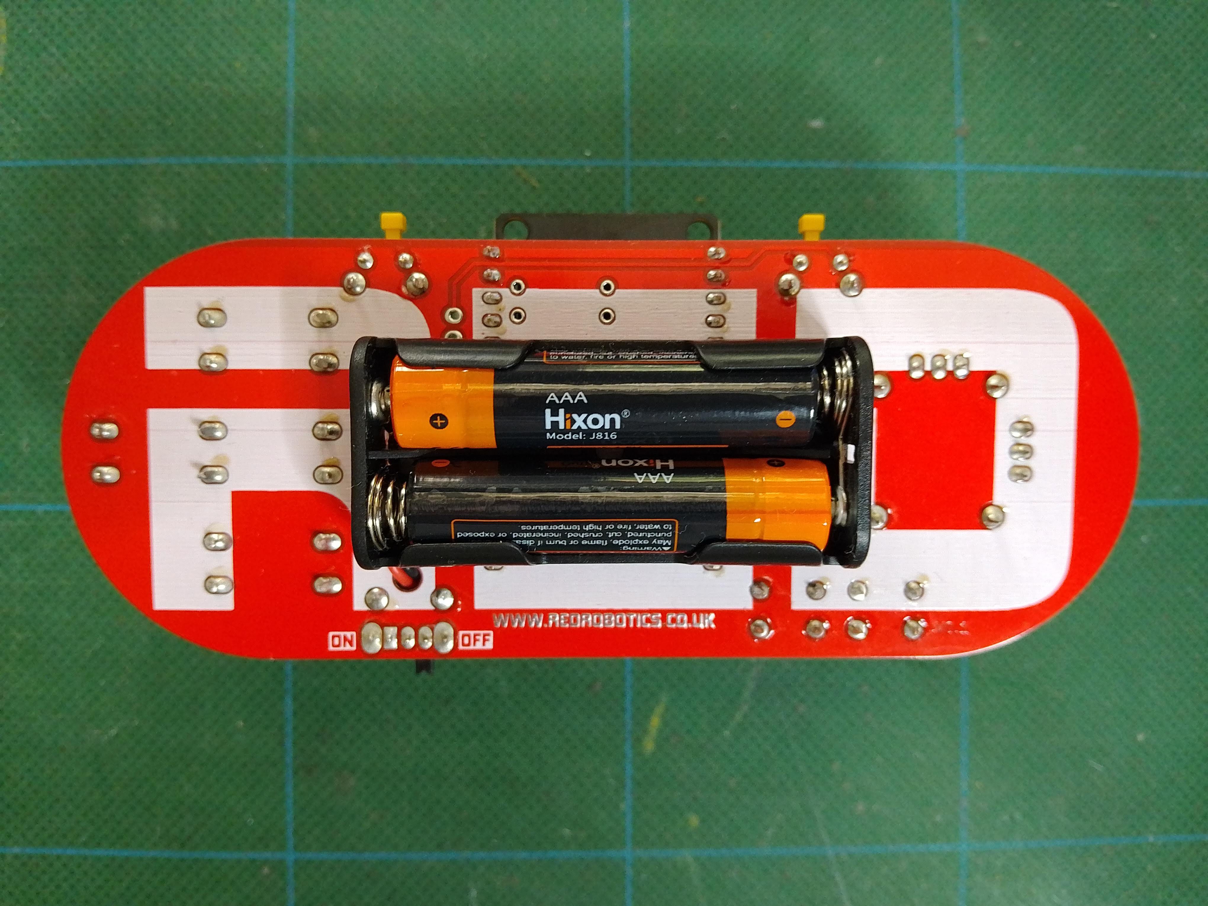
Here's the first iteration. It uses the 30 pin ESP Devkit, as this was the cheapest option if you buy them in packs. It has a joystick with 2 analogue axis and 9 buttons, It's powered by 2 AAA batteries.


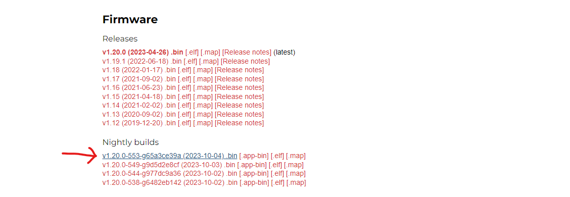
I wanted to use MicroPython, but ESP-NOW is not included in the main MicroPython firmware. You have to use the nightly build, you can download it here: MicroPython_ESP32
Make sure you download the nightly build:

You can upload the new firmware to your ESP32 device using Thonny (as detailed in a previous log).
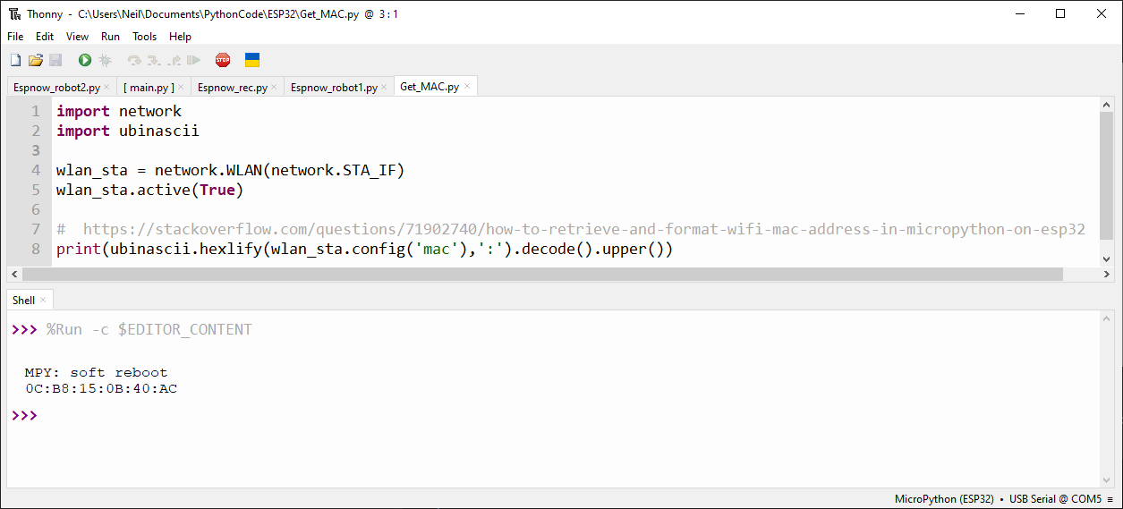
Once you have the firmware installed, you need to get the MAC address of the receiving device, in this case our robot. Run the following code on the ESP32 device in your $10Robot!
import network
import ubinascii

wlan_sta = network.WLAN(network.STA_IF)
wlan_sta.active(True)

#  https://stackoverflow.com/questions/71902740/how-to-retrieve-and-format-wifi-mac-address-in-micropython-on-esp32
print(ubinascii.hexlify(wlan_sta.config('mac'),':').decode().upper())
You should see the MAC address in the output window.

Make a note of the MAC address as you'll need it in your controller code. It's also worth writing it on a little sticky label and sticking it on the robot.
Now load the following code onto the ESP32 in the controller.
import network
import espnow
from machine import Pin, ADC
from time import sleep

Y_Pot = ADC(Pin(36))
Y_Pot.atten(ADC.ATTN_11DB) #  0 - 3.3V range
Y_Pot.width(ADC.WIDTH_9BIT)
X_Pot = ADC(Pin(39))
X_Pot.atten(ADC.ATTN_11DB) #  0 - 3.3V range
X_Pot.width(ADC.WIDTH_9BIT)

UP = Pin(5, Pin.IN, Pin.PULL_UP)
DOWN = Pin(15, Pin.IN, Pin.PULL_UP)
LEFT = Pin(16, Pin.IN, Pin.PULL_UP)
RIGHT = Pin(4, Pin.IN, Pin.PULL_UP)

L1 = Pin(32, Pin.IN, Pin.PULL_UP)
R1 = Pin(23, Pin.IN, Pin.PULL_UP)
L2 = Pin(33, Pin.IN, Pin.PULL_UP)

START = Pin(14, Pin.IN, Pin.PULL_UP)
SELECT = Pin(13, Pin.IN, Pin.PULL_UP)

# A WLAN interface must be active to send()/recv()
sta = network.WLAN(network.STA_IF)  # Or network.AP_IF
sta.active(True)
#sta.disconnect()      # For ESP8266

e = espnow.ESPNow()
e.active(True)
peer = b'\x0A\x0B\x0C\x0D\x0E\x0F'   # MAC address of peer's wifi interface
e.add_peer(peer)      # Must add_peer() before send()
print("Start")

while True:
    Y_Raw = Y_Pot.read()
    X_Raw = X_Pot.read()
    Y = int(Y_Raw/2) # Convert to 8bit
    X = int(X_Raw/2) # Convert to 8bit

    e.send(peer, b'start', True)

    e.send(peer, str(Y), True)
    e.send(peer, str(X), True)

    e.send(peer, str(UP.value()), True)
    e.send(peer, str(DOWN.value()), True)
    e.send(peer, str(LEFT.value()), True)
    e.send(peer, str(RIGHT.value()), True)

    e.send(peer, str(L1.value()), True)
    e.send(peer, str(R1.value()), True)
    e.send(peer, str(L2.value()), True)
    e.send(peer, str(START.value()), True)
    e.send(peer, str(SELECT.value()), True)
Remember to change the peer MAC address on line 32 to match the one in your robot.
Now load the following code onto the ESP32 in your robot.
import network
import espnow
import ubinascii
import time
from machine import Pin

# A WLAN interface must be active to send()/recv()
sta = network.WLAN(network.STA_IF)
sta.active(True)
#sta.disconnect()   # Because ESP8266 auto-connects to last Access Point

e = espnow.ESPNow()
e.active(True)

# Set up motors
M1a = Pin(18, Pin.OUT)
M1b = Pin(19, Pin.OUT)

M2a = Pin(25, Pin.OUT)
M2b = Pin(26, Pin.OUT)


data =[0,0,0,0,0,0,0,0,0,0,0,0] # List to store controller data
count = 0
UP = 0
DOWN = 0
LEFT = 0
RIGHT = 0

print("Press CTRL-C now to stop program")
time.sleep(2)
print("Start")

while True:
    host, msg = e.recv()
    if msg:             # msg == None if timeout in recv()
        if msg == b'start': # Look for the start of the message and reset the count
            count = 0

        if count != 0:
            data[count] = int(msg) # Load the message data into the list

        count +=1

        if count == 12: # End of message
            count = 0
            #Uncomment the following line to show all data from the controller
            #print('{:03d}'.format(data[1]),'{:03d}'.format(data[2]),data[3],data[4],data[5],data[6],data[7],data[8],data[9],data[10],data[11])

        if data[3] == 0 and UP == 0:
            UP = 1
            print("UP Pressed")
            M1a.value(0)
            M1b.value(1)
            M2a.value(0)
            M2b.value(1)

        elif data[3] == 1 and UP == 1:
            UP = 0
            print("UP Released")
            M1a.value(0)
            M1b.value(0)
            M2a.value(0)
            M2b.value(0)

        if data[4] == 0 and DOWN == 0:
            DOWN = 1
            print("DOWN Pressed")
            M1a.value(1)
            M1b.value(0)
            M2a.value(1)
            M2b.value(0)

        elif data[4] == 1 and DOWN == 1:
            DOWN = 0
            print("DOWN Released")
            M1a.value(0)
            M1b.value(0)
            M2a.value(0)
            M2b.value(0)


        if data[5] == 0 and LEFT == 0:
            LEFT = 1
            print("LEFT Pressed")
            M1a.value(1)
            M1b.value(0)
            M2a.value(0)
            M2b.value(1)

        elif data[5] == 1 and LEFT == 1:
            LEFT = 0
            print("LEFT Released")
            M1a.value(0)
            M1b.value(0)
            M2a.value(0)
            M2b.value(0)


        if data[6] == 0 and RIGHT == 0:
            RIGHT = 1
            print("RIGHT Pressed")
            M1a.value(0)
            M1b.value(1)
            M2a.value(1)
            M2b.value(0)

        elif data[6] == 1 and RIGHT == 1:
            RIGHT = 0
            print("RIGHT Released")
            M1a.value(0)
            M1b.value(0)
            M2a.value(0)
            M2b.value(0)
If all goes well, you should be able to drive your robot!
This was just a simple test to see if it worked. I was very pleased it was just as responsive as the PlayStation controller. It had a range of about 20 metres. I'll add some more code soon, using the joystick with analogue speed control.
 Neil Lambeth
Discussions
Become a Hackaday.io Member
Create an account to leave a comment. Already have an account? Log In.
Do you mean using the analogue joystick to drive the robot? It's on my list of things to do, I'll look into it...
Are you sure? yes | no
Did you make any progress with this? I've been trying to make a joystick remote control using micropython but haven't had much luck.
Are you sure? yes | no