 Guillermo Perez Guillen
In this section I will show you how to assemble the water sprayer system that I have designed for this project.
Schematic Diagram
First of all, we need to know how this system will be connected and its basic operation. Below I show you the schematic diagram:

How does it work?
- If the Nicla Vision board detects a bee, then it turns ON the green LED and the PG1 pin for 1.5 seconds;
- If the MKR WAN 1310 board detects a pulse through pin 4, then it activates the bee counter, and prints the number of bees through the serial port;
- If the Nicla Vision board detects a wasp, then it turns ON the red LED and the PG12 pin for 1.5 seconds;
- If the MKR WAN 1310 board detects a pulse on pin 5, then it activates the servo motor and the wasp counter, finally prints the number of wasps through the serial port;
- When the servo motor is activated, it rotates from 105 to 170 degrees with the gripper to press the water spray bottle for 1.5 seconds, then returns to the initial position of 105 degrees.
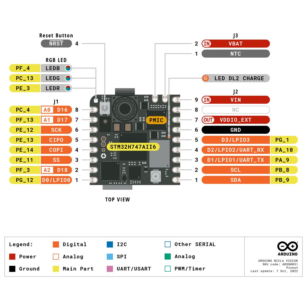
It's also necessary to know the pinout of the Nicla Vision and MKR WAN 1310 boards that I will use in my prototype.
Nicla Vision Pinout
MKR WAN 1310 Pinout

Assembling the device
Below I show you the gripper that we will use, as you can see it has a MG995 servo, which has a stall torque from 8.5 kgf·cm (4.8 V ) to 10 kgf·cm (6 V) . Here the datasheet: https://www.electronicoscaldas.com/datasheet/MG995_Tower-Pro.pdf

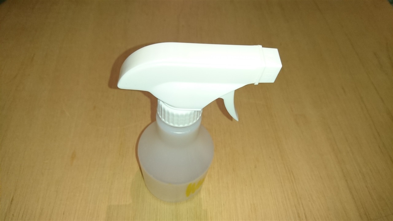
The handheld water sprayer is a generic 250 ml.
I have mounted the devices on an old CD case, which is ideal since the water spray bottle doesn't stop the movement of the gripper when it works.

But if you have enough time and filament to 3D print similar boxes, here are the STL files for you to modify and print. Below I show you module 1, which is an empty box on the inside and with the holes to insert the cables you need to connect a battery for example.

Finally module 2. We can use this piece for the base of module 1 or to assemble the Nicla Vision. In my case, I fixed it using two rubber bands to hold the USB cable since the Nicla Vsion lacks holes to fix it with screws.
Here I show you a zoom of the handheld water sprayer mounted on the gripper using a single nylon strap.

Now the Nicla Vision mounted in module 2, by means of the USB cable fixed with a couple of rubber bands.

Finally the MKR WAN 1310 mounted on the opposite side of the Vision nicla and on module 2.

Below I show you an image of the frontal view after wiring the Nicla Vision and MKR 1310 boards.

And below I show you an image of the back view.


Discussions
Become a Hackaday.io Member
Create an account to leave a comment. Already have an account? Log In.