 rusher
Background
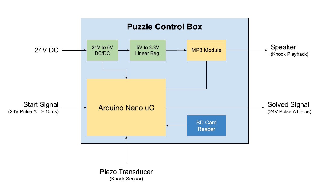
I developed this puzzle for a local escape room. Their control system is based on a PLC with 24VDC I/O, and I designed the puzzle according to their interface specifications. The puzzle does not have an implicit reward or anything, it just sends a "solved" signal to the control system to trigger consecutive events. One requirement was that the knock-sequences could be modified by a non-technical user, hence the SD-Card.
A PDF with the complete documentation and BOM is available in the Files section.
Functional Description
Start Puzzle
The Arduino Nano MCU runs the puzzle software. On boot, the MCU loads the list of preset knock-sequences from the “patterns.txt” file on the SD card. After that, the system waits for the start signal pulse.
Audio Playback
The start signal pulse triggers audio playback of the first knock sequence: the MP3 module contains a single “knock” sound. The MCU repeatedly triggers playback of the single knock, with longer and shorter intervals as directed by the preset knock-sequence data.
Knock Detection
After playback, the system pauses for several seconds before resuming playback of the same pattern. During the pause, players can repeat back the sequence by knocking on a designated surface.
A piezo disc transducer is mounted on the backside of the designated knock area. The mechanical shock from the knock is converted into an electrical signal and detected by the MCU by using an external interrupt. The MCU records the time between knocks to differentiate long and short pauses, and stores the “player knock-sequence” in memory.
Pattern Matching
The player input knock-sequence is compared with the preset knock-sequence. If the sequences match, the puzzle advances to the next pattern in the preset sequence list.
Puzzle Solved
After successfully repeating the last knock sequence, the MCU outputs a 5s long “solved” signal pulse. The MCU automatically resets the puzzle and returns into a waiting state until the next start signal pulse is detected.
Comments on the Circuit
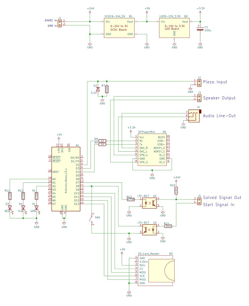 |  |
Looking at the circuit, you can see that I used a lot of premade modules, and used optocouplers to translate the 5V/24V signals. If you decide on building this yourself, don't omit the 5.1V Zener with the 100K parallel resistor on the piezo input: they protect the MCU from the high piezo voltages and help to reliably trigger the ISR.
Also: technically the device features a 3.5mm line-out to hookup an external amplifier, but the sound-quality on that output is terrible. I wouldn't have bothered adding the 3.5mm jack it if I knew that it would sound that bad.
Comments on the Code
Just look at the code, so many comments. What I'm most proud of: I measure the relative time between the user input-knocks, i.e. differentiating short and long pauses is not based on some preset times, but on the users "input style". Just knock the way you like to knock, and the MCU will figure out what knocks are long or short. I did this because I've encountered similar puzzles before, and even if I knew the correct sequence, it always required multiple attempts to get my long/short timing into a region that the puzzle circuit could differentiate correctly.
 jason.gullickson
 E/S Pronk
 Michael Erberich