 kelvinA
I'd still like to see what the smallest possible version of this solution of this heatblock would be.
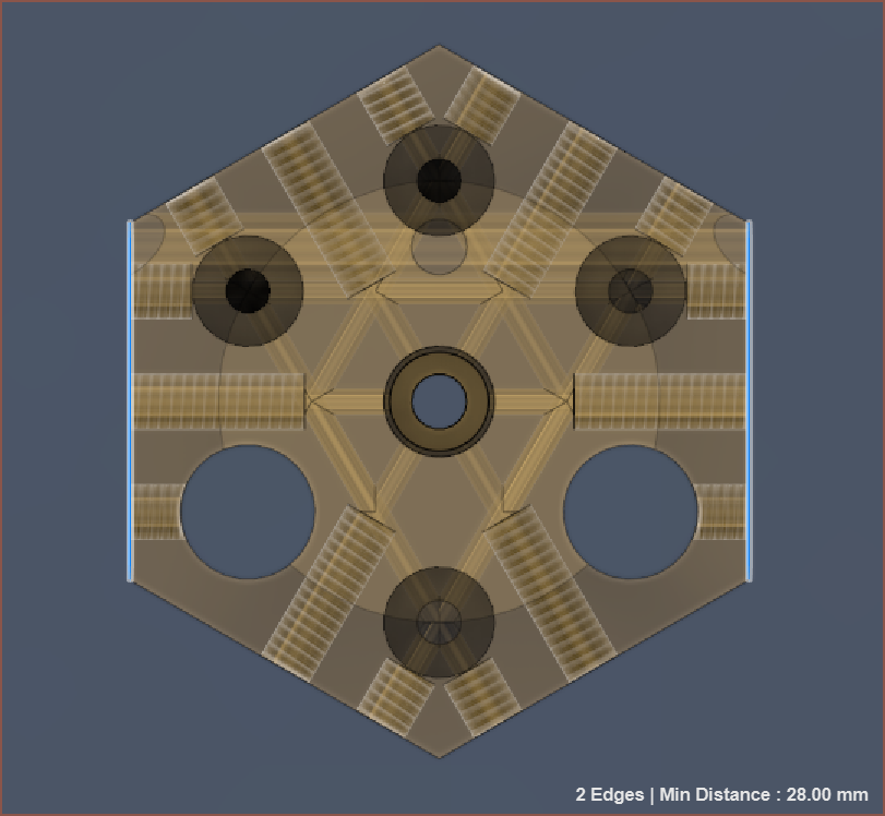
Using a custom heatsink instead of something off-the-shelf, the smallest size I believe is manufacturable is 28mm across flats, reducing the mass from 208g to 101g and the shortest material path length from 49.28mm to 40.62mm.
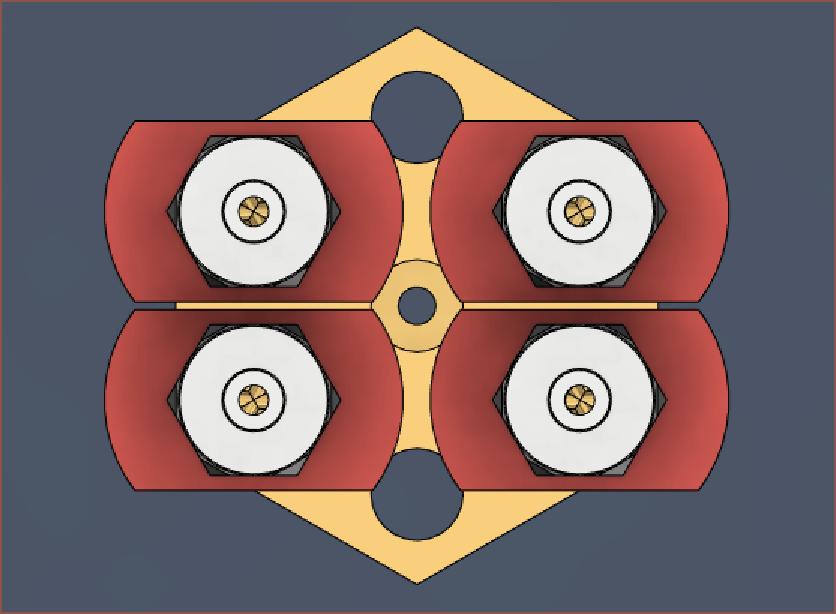
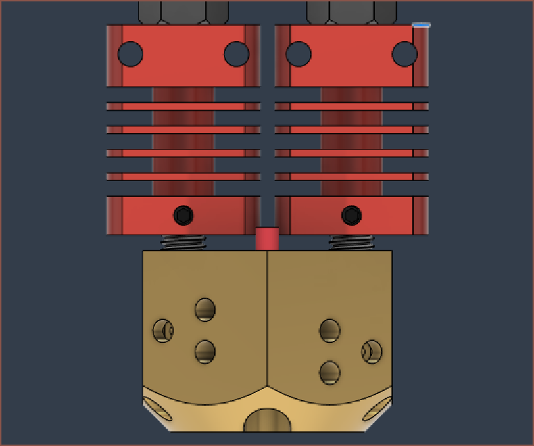
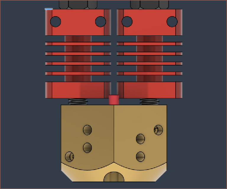
The cheap dual extruder heatsinks are slightly too large to opt for a 4-input solution:
It does seem that 32mm across flats could obtain a solution that can use the very cheap CR-10 / Ender3 heatsinks, with a mass of 138g (1/3 reduction):
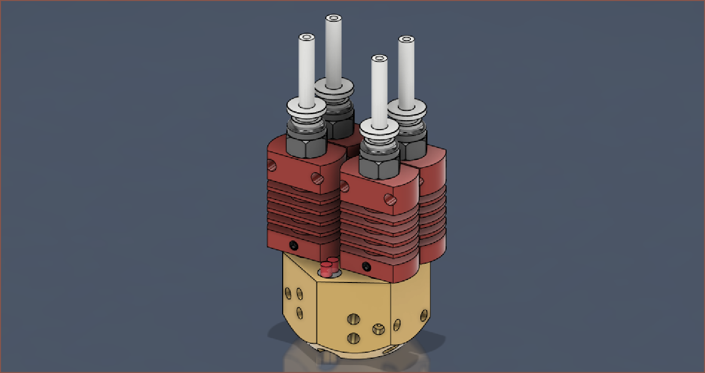
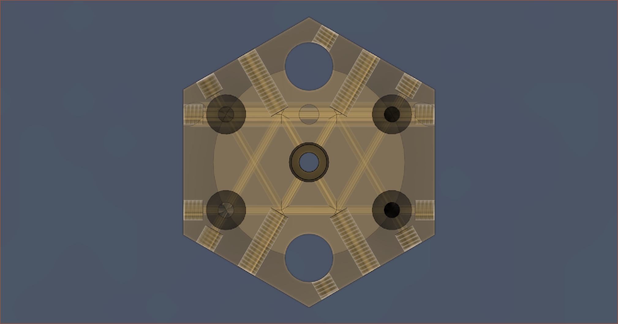
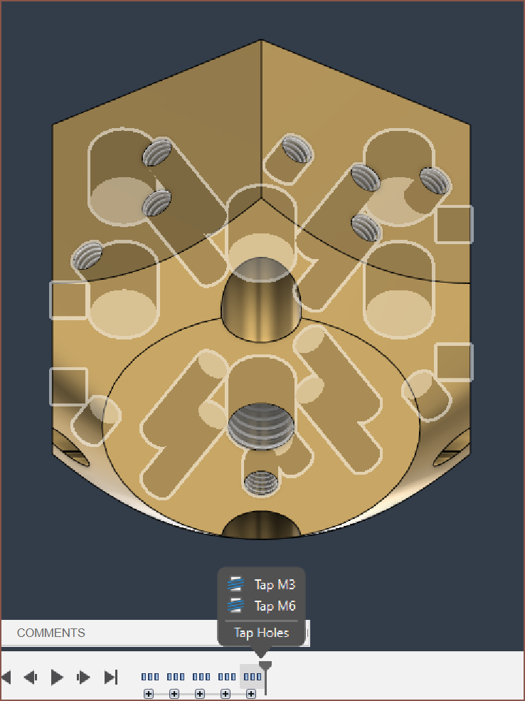
An unintended feature is that the drilled holes make a nice, more ordered looking pattern, though the grub screws for holding the heater cartridges aren't in the model:
This also looks more straightforward to aircool and mount.
Why is project optimisation so slow?
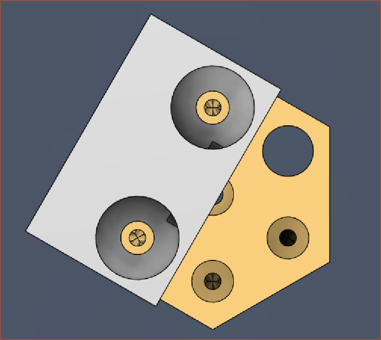
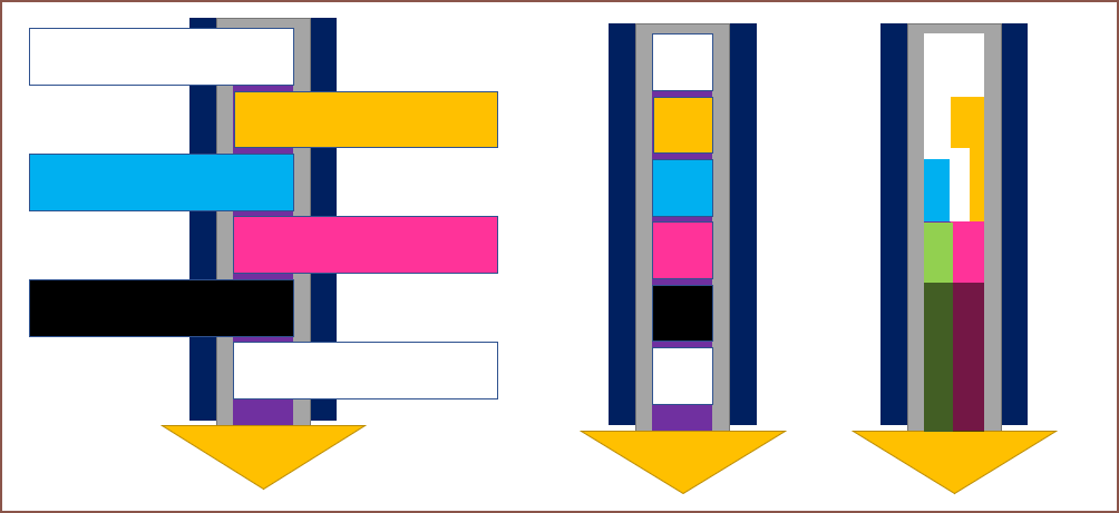
Anyway, if mounted straight to the X carriage, this is the difference between the current and optimised one:
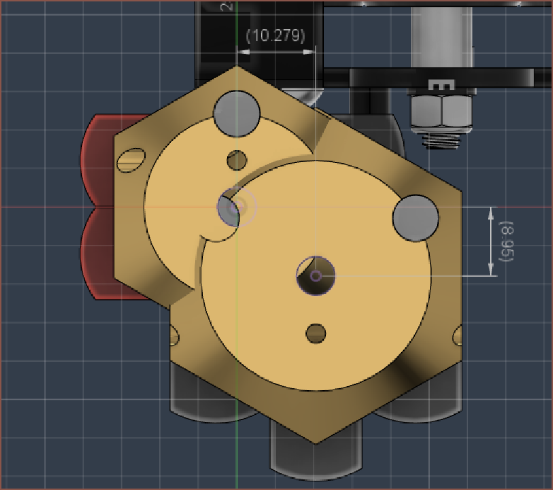
I gain 9mm of Y but lose 10.3mm of X.
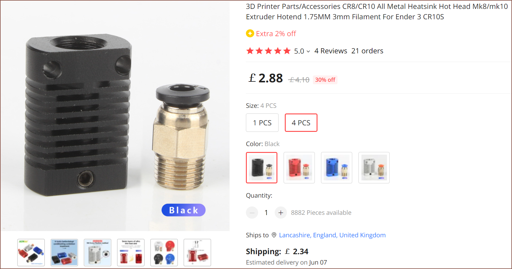
In other news, I found this hotend that also uses the same heatsinks, dual 6x20mm cartridges and 3x20mm thermistor:
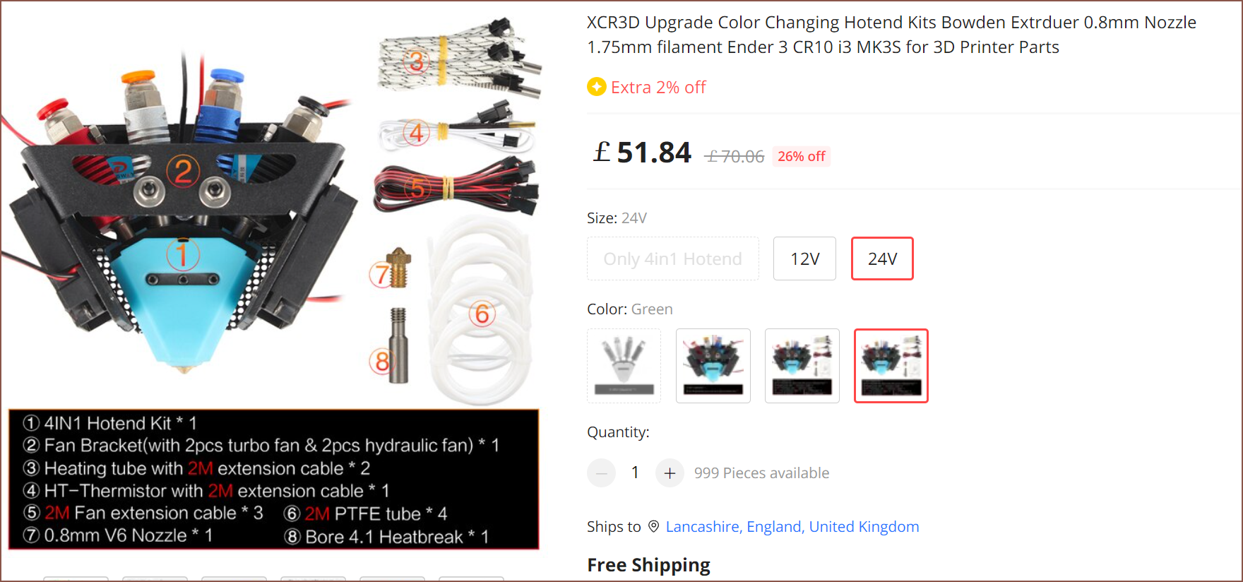
So it might be possible that an AliExpress seller could make a £70-or-so kit.
[May 1, 12:00]
Seems that it'll be possible to actually have 5 filament inputs whilst only using 4 heatsinks, a cylindrical metal file and a 3D printed jig:
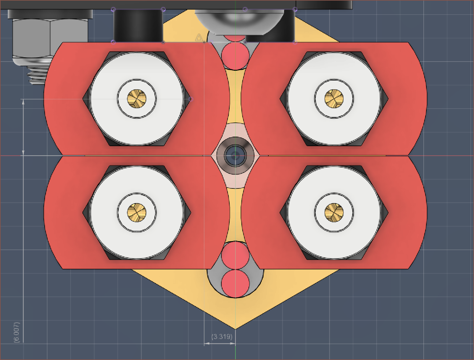
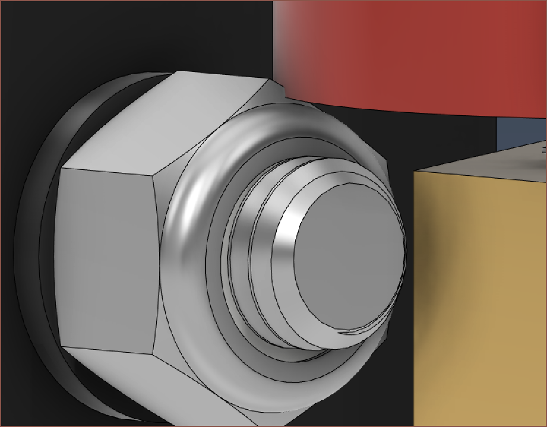
It's cutting it close though:
[14:10] I've gone through and created a new 2D drawing, and since the actual 1:1 drawings are smaller now, I've been able to fit everything onto 1 single page instead of 3:
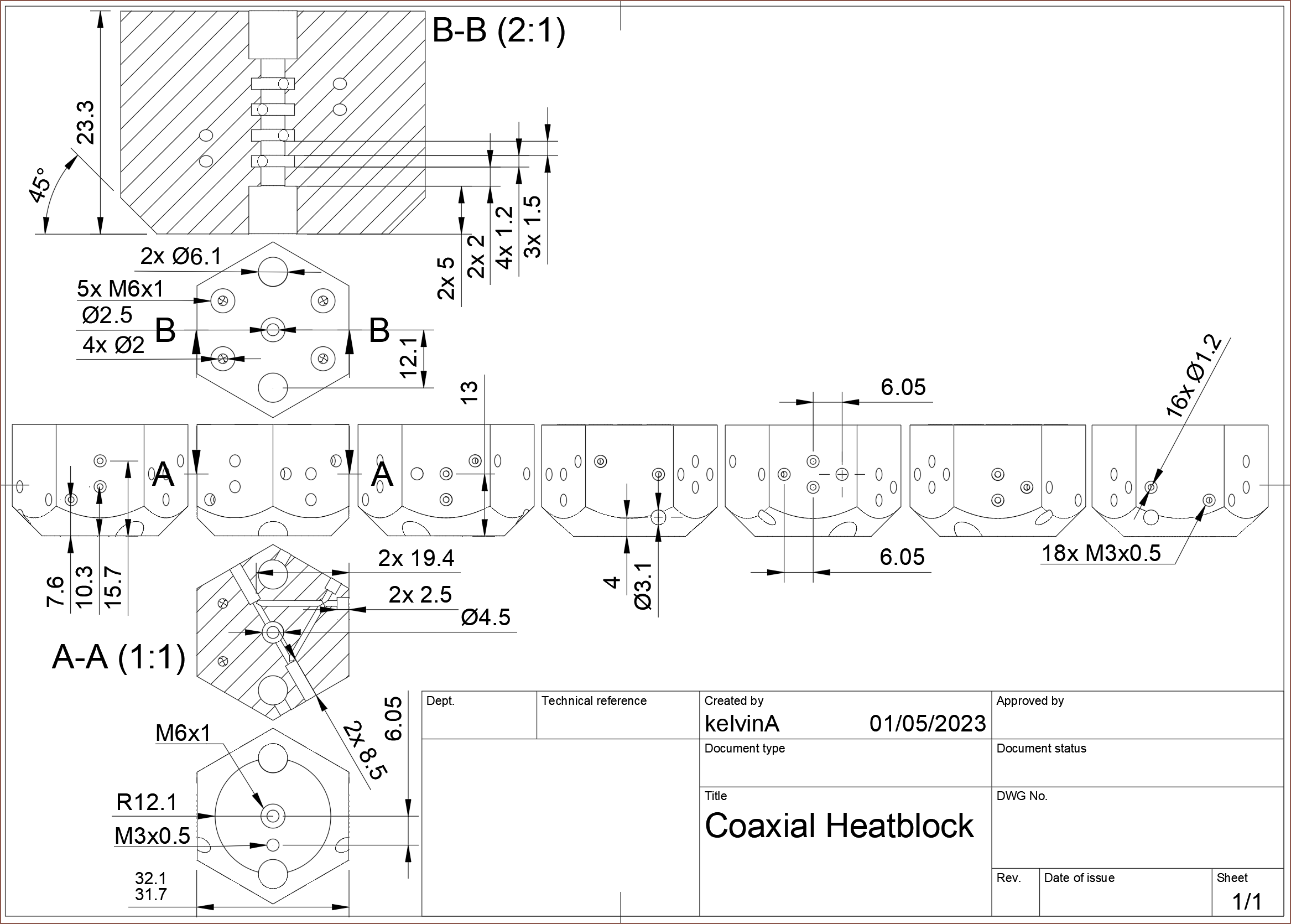
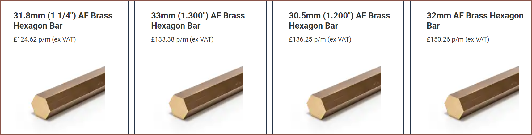
I think this is also much easier to understand than 4 cross sectional views of essentially the same geometry on one page solely for marking tapped holes and then duplicate views on the other 2 pages. The across-flat dimension is toleranced so that either 31.8 or 32mm raw stock can be used, of which the former has a price cut:
This design might make it harder to implement reliable wire/fiber feeding, but if I've got time for trying that, I've got time to continue work on the #SecSavr Suspense [gd0105] in the goal to obtain photographic (270 voxels per inch) 3D prints.
Internal geometry:
Asking PCBWay is free to try, so I might as well:
I might find that, during testing, I need a 3mm OD center shaft and a custom bi-metal heatbreak with a 2.4mm OD stainless steel tube that extends 13mm into the heatblock. I'm just concerned that the extrusion will be coated unevenly because the centre is soft and molten.
In other news, I knew all of this seemed kind of familiar. This is a concept I made an unknown amount of years ago:
I've also found what seems to be prior art, and I remember seeing concept B:
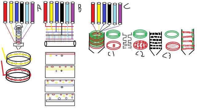
Concept C1 seems to be a possible alternative way to obtain the internal grooves.
[18:30] I've gone through and grouped + named all features in the file because I think this design is at a good quality level.
Discussions
Become a Hackaday.io Member
Create an account to leave a comment. Already have an account? Log In.