 kelvinA
[07:00] I wake up and I get this:
From PCBWay:

Sorry, our factory does not have a suitable cutting tool for
processing your parts. You have two options:
    1. If the internal groove is not useful, we suggest you remove
       it.
    2. Increase the size of the hole to 5mm or more, and your
       internal groove will also increase accordingly.
Me: A solution... is being processed. (plays electro/cyber background music)
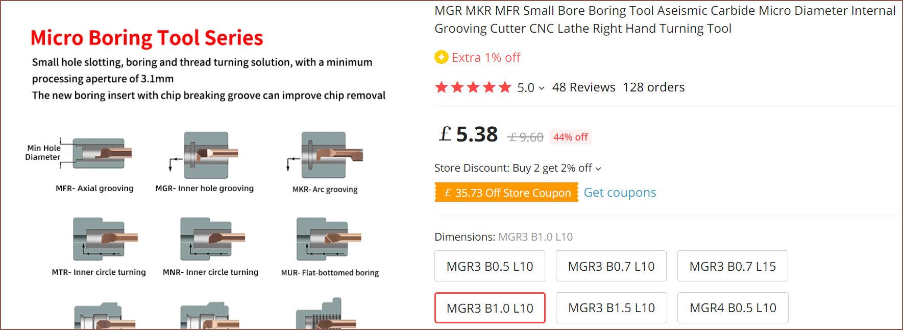
Obvioulsy, both 0mm internal groove and 5mm outer bore is a nogo and the solution will fail. However comma (Swoozie reference), I probably should've checked AliExpress first and not the wider internet when looking to see if a micromachining grooving part existed:
My university CNC technitians also probably don't know of AliExpress' existance, though I could understand that expensive 5-axis machines usually are paired with expensive tool bits (they said some are £200).
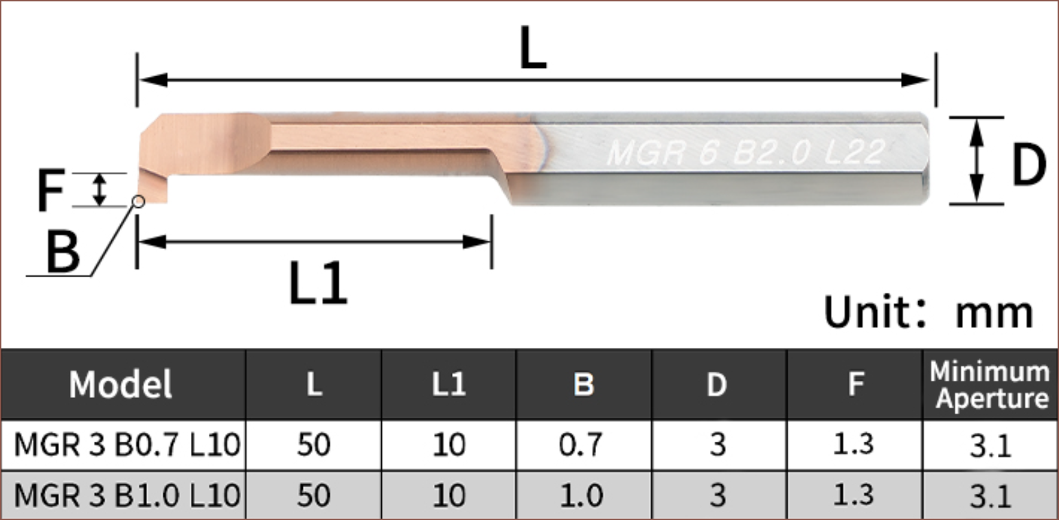
At least with this, it's more applicable for a maker with a metal lathe in this day and age to create this part. I can only imagine that the F dimension is a square, since the bore dimension isn't dimensioned the same way as the other lengths, though I can imagine if B is supposed to be the dimension parallel to L1.
0.6^2 * pi = 1.131mm^2
1.4 * 1.4  = 1.96mm^2
So, even with a 0.7mm groove, I should still have a pressure drop from the 1.2mm internal channel if CSA is anything to go by.
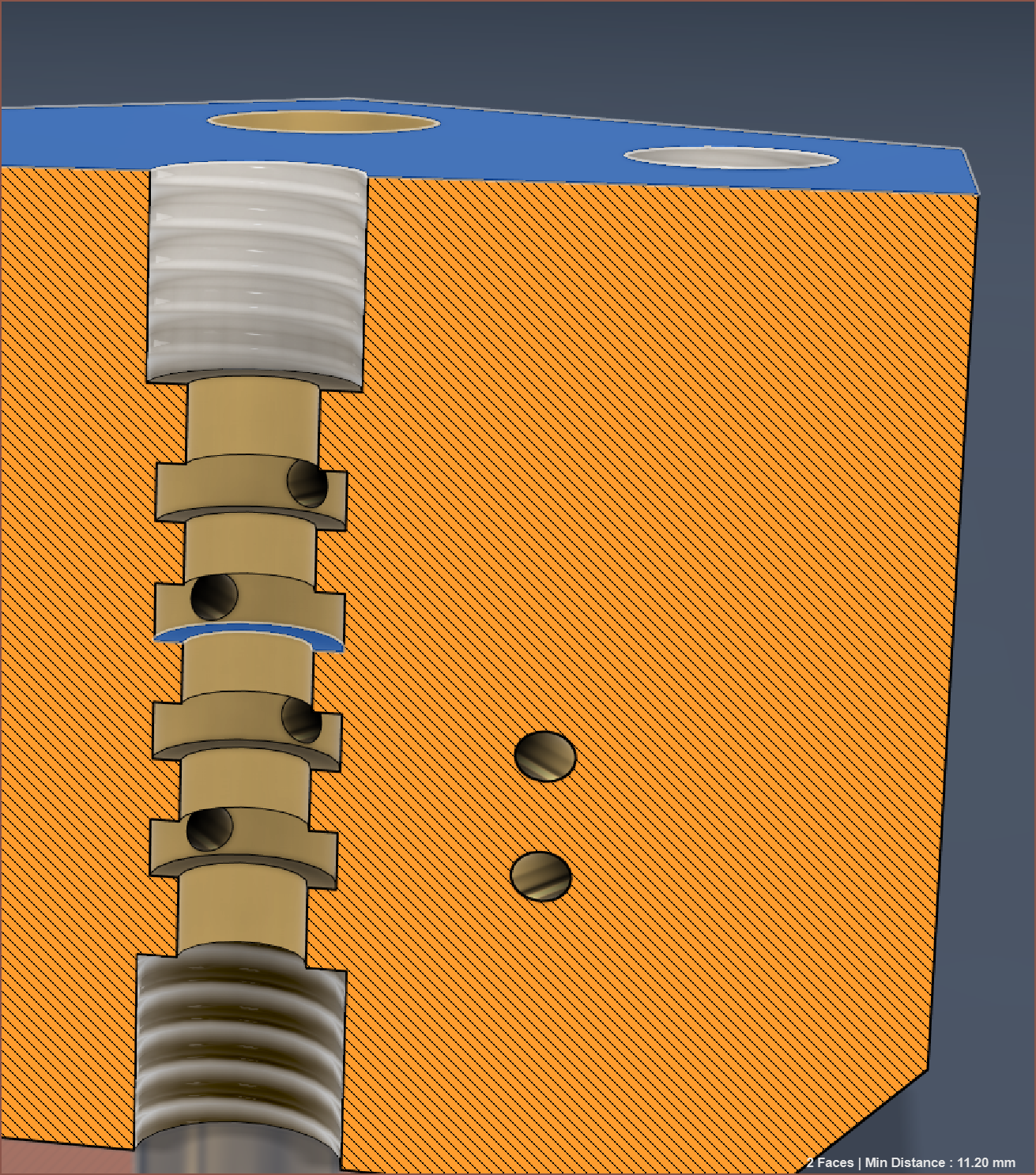
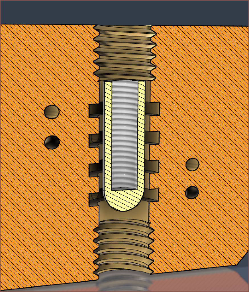
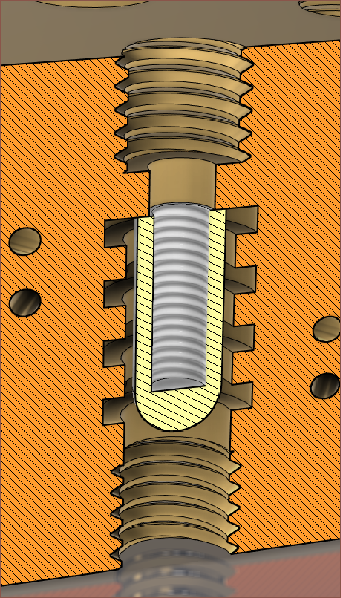
If they can only approach to the top of the part, L1 = 15 will be needed:
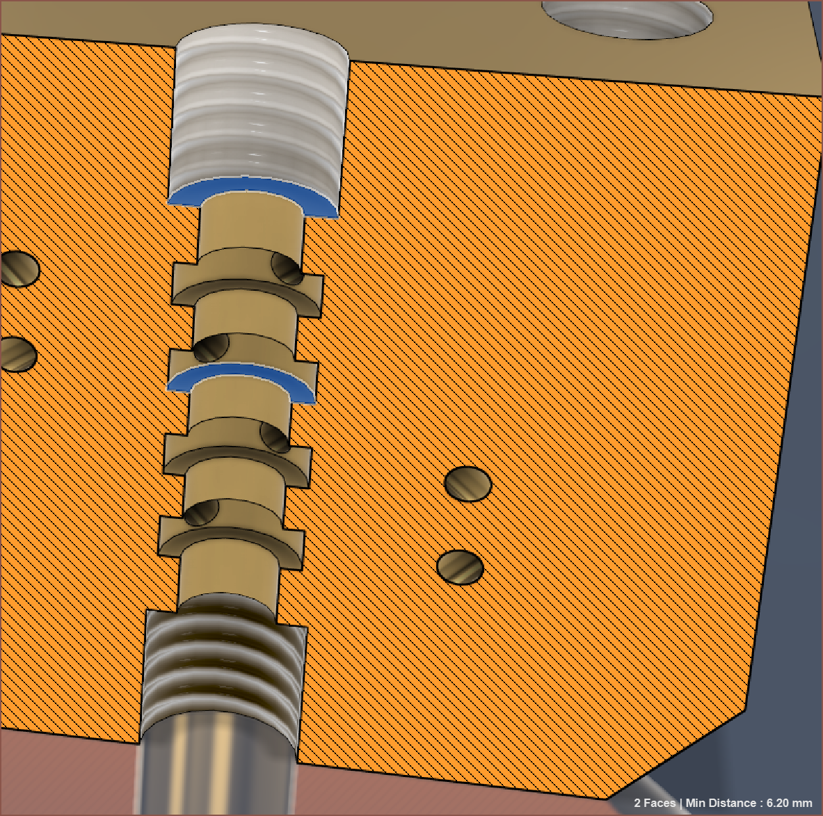
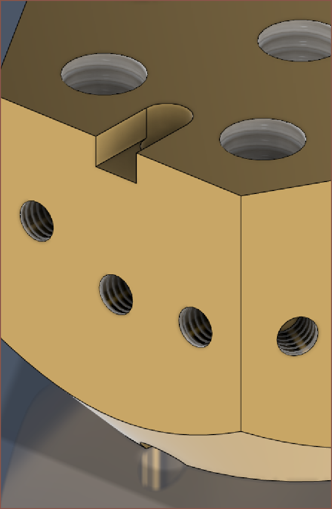
However, I can't see why it's not possible to go into the tapped hole. There, for a 1.4mm tall groove, the distance is only 6.2mm:
The length of this would be 24mm. The groove diameter stays at 4.5mm for a 0.7mm internal cut.
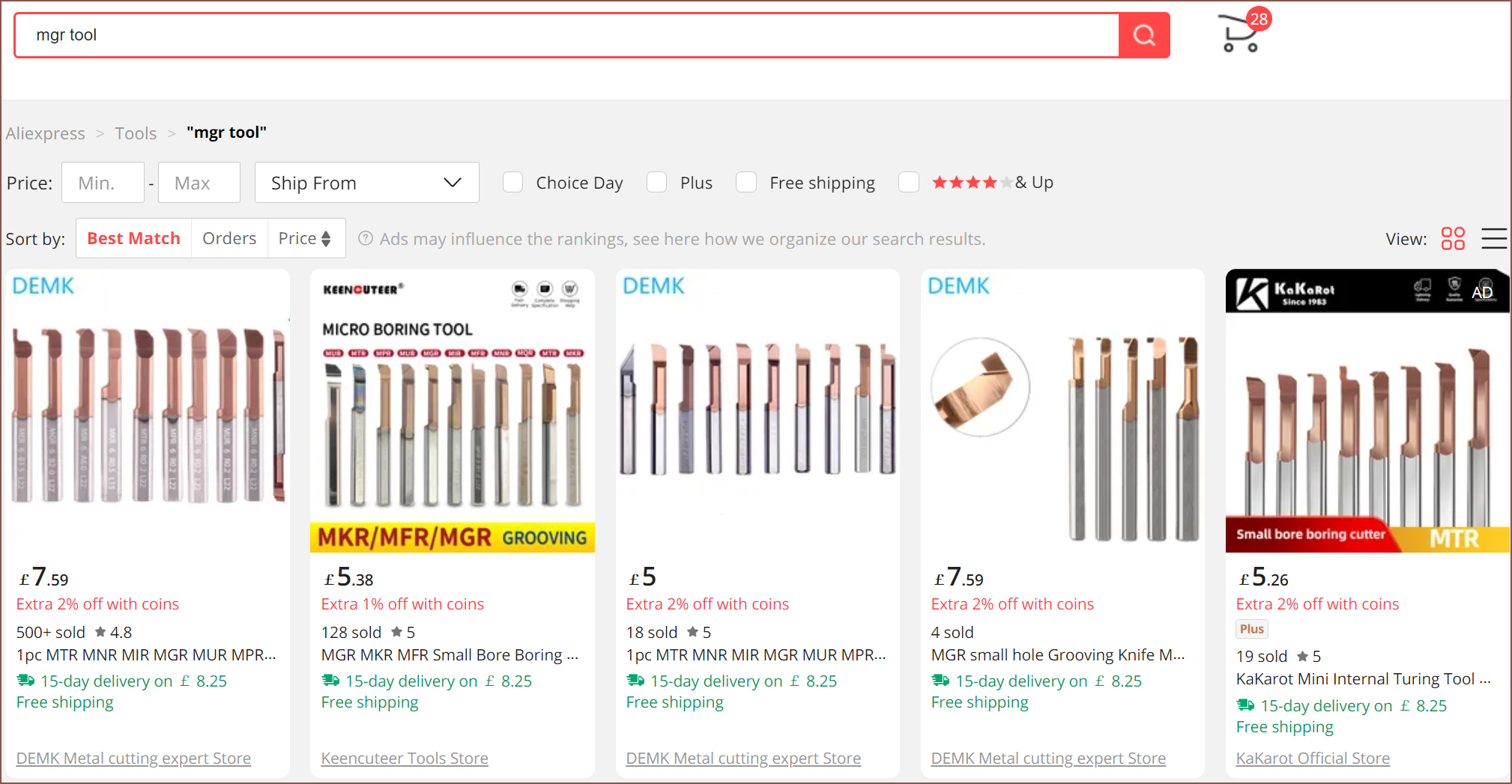
It also turns out MGR tools are standard and not something niche:
I've also found something that confirms my estimate about dimension B:
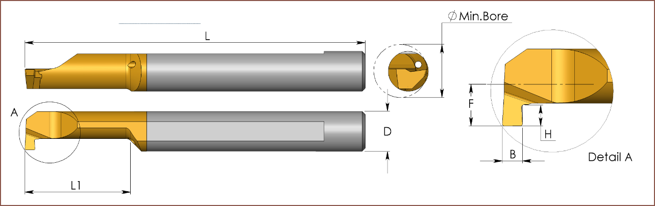
And then I found this:
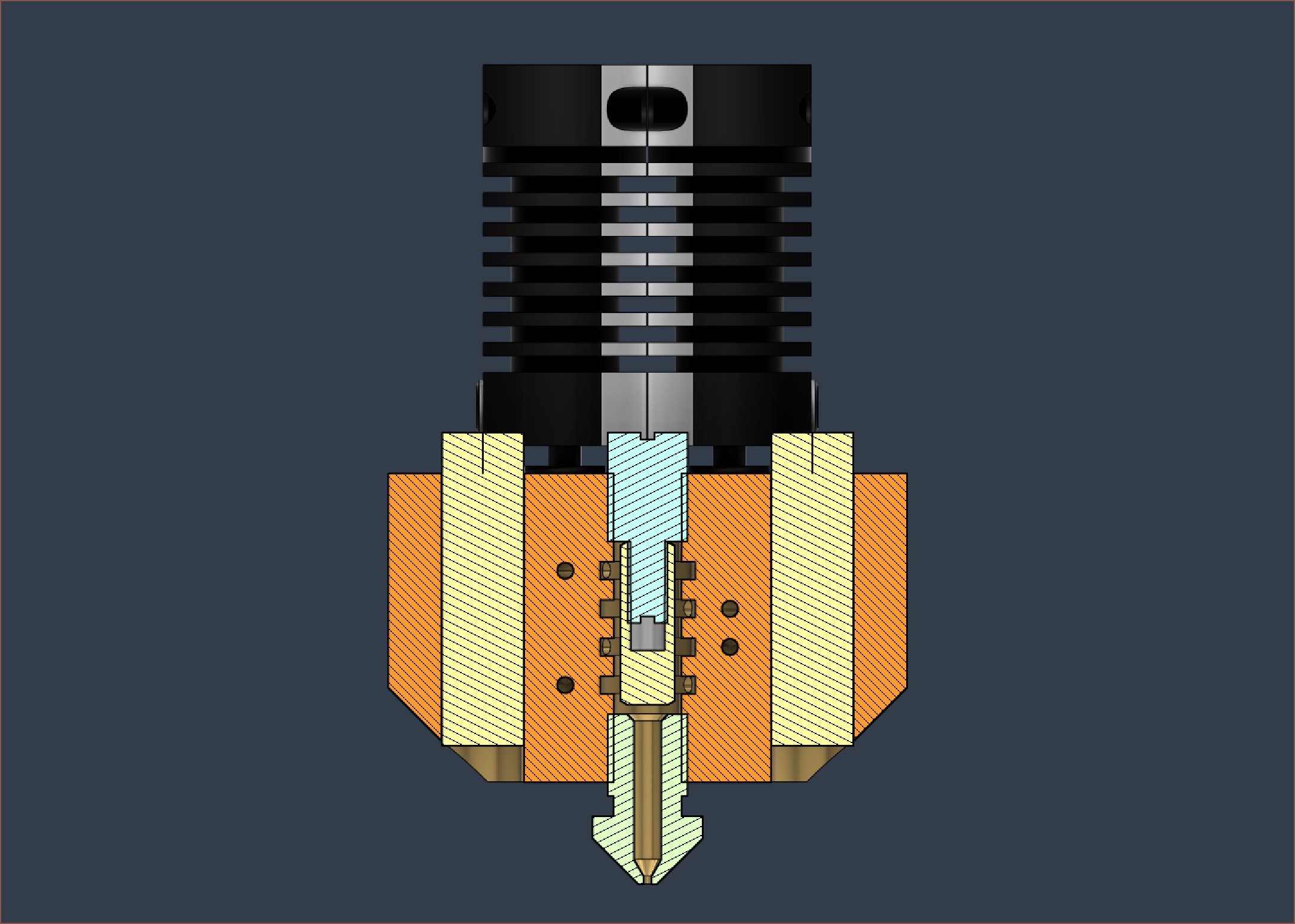
Looking at the rightmost view... I'm starting to see why... PCBWay asked for a 5mm center hole, or at least larger than 3mm. Not sure why 5 though. I'd imagine 4mm would've worked though.
Okay... so looks like that insert / tube is non-optional.
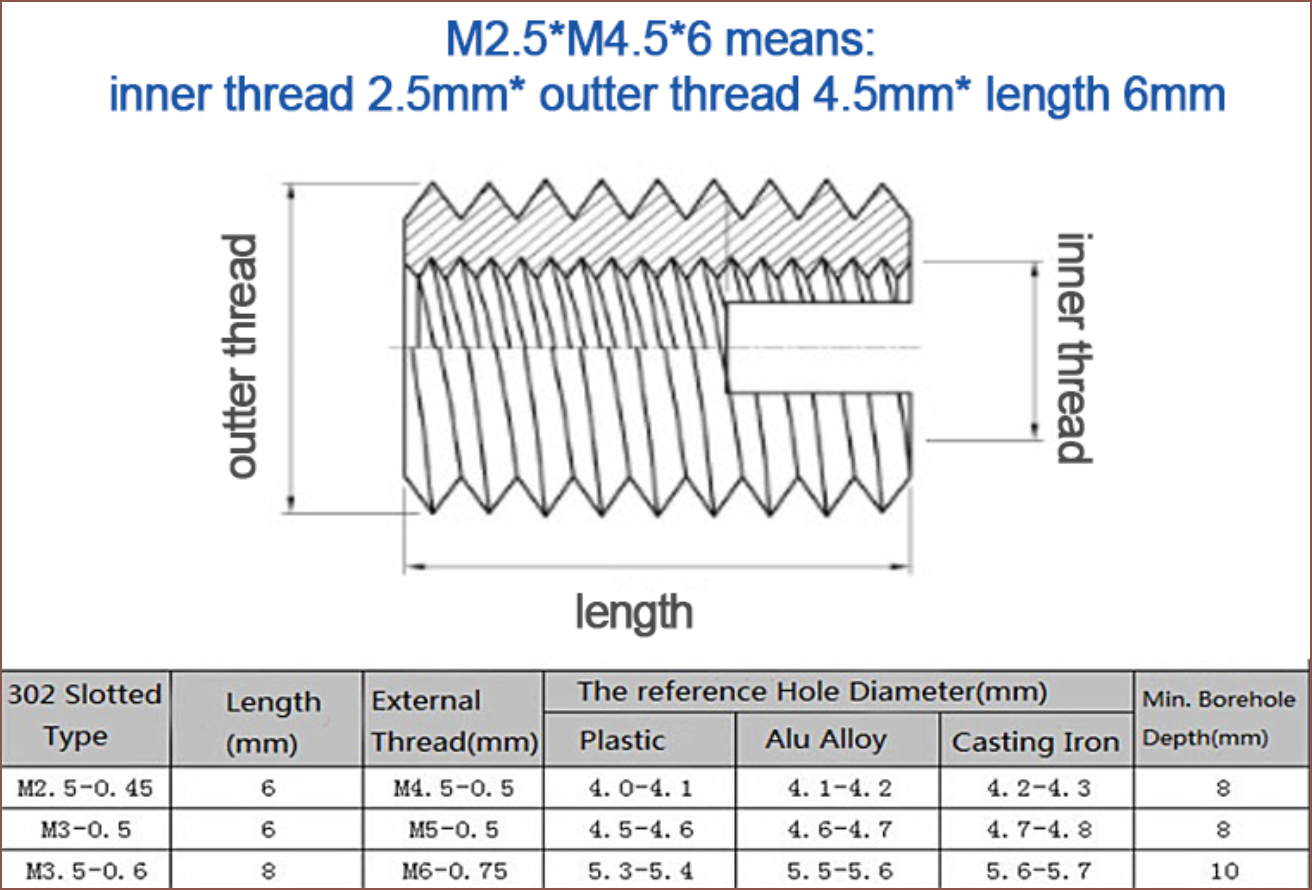
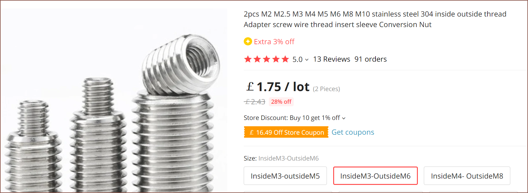
Also unfortunately, for M3 bolts, these inserts have an M5 outer thread instead of M6:
WAIT! THERE'S HOPE! LOOK:
Not all that sure how you'd tighten it. I assume the bolt turns in the same direction, so tightening it also tightens the outer thread. Then, I don't know how you'd get the thread out again other than using pliers.
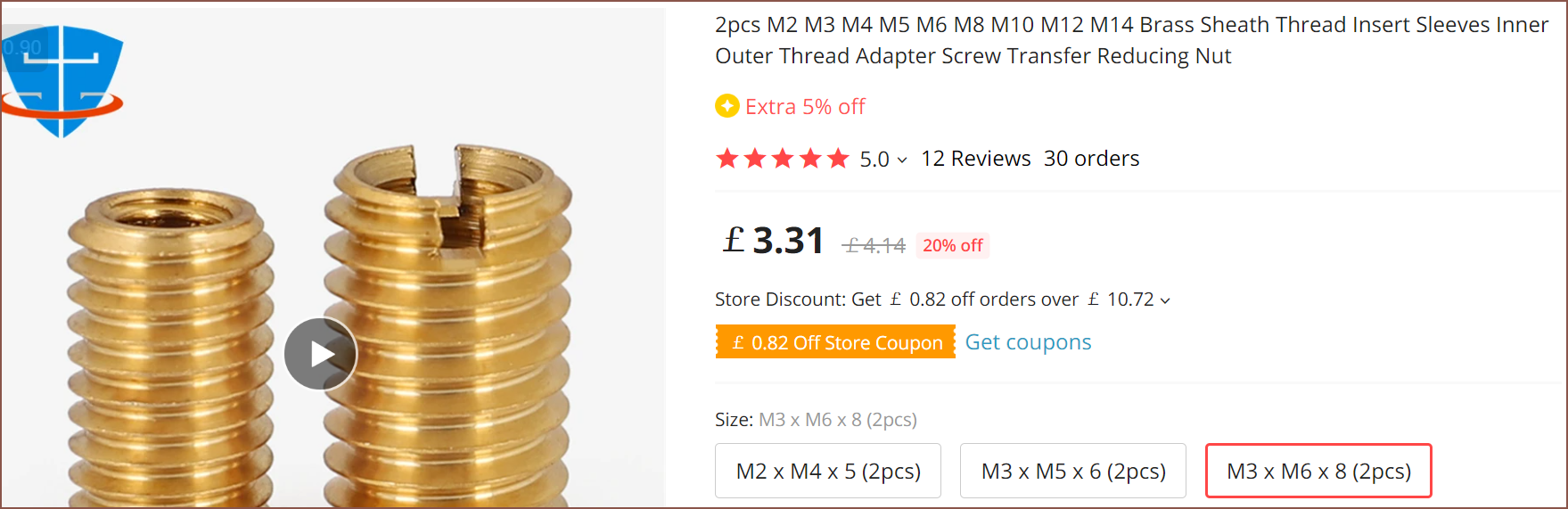
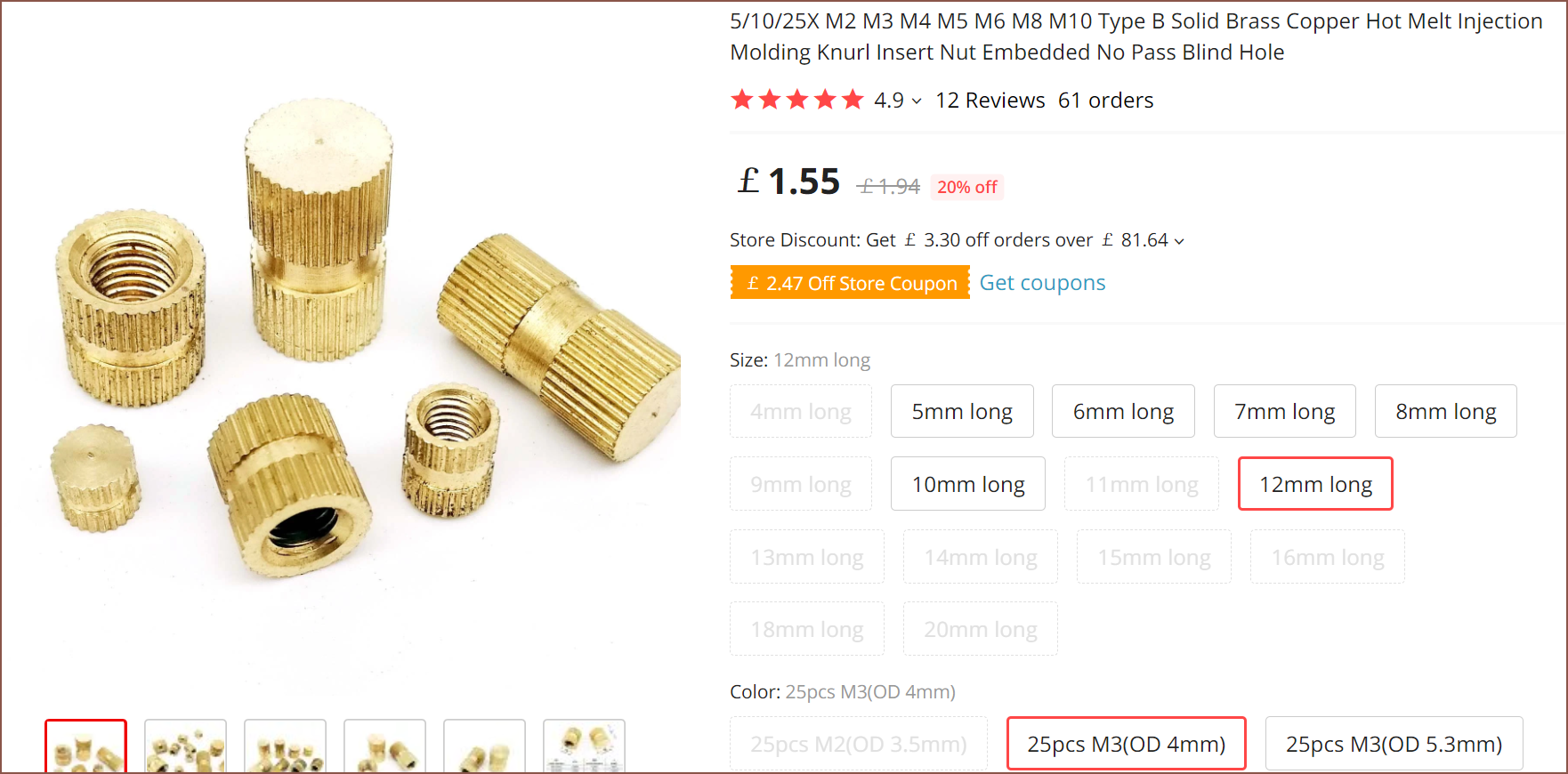
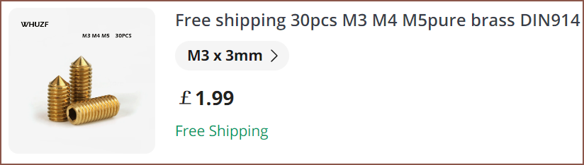
Muhahaha it comes in brass!

AND with a slot so that unscrewing is possible! Sugoi. Unfortunately, the mental simulation predicts leaks using this method, creeping up through the small gap between the M3 bolt and threads.
There's also these things, but I don't know how I'd tighten them:
Again, not sure how to tighten. Cut your own, perhaps?

Drats! This is just what I need, but M6->M3!
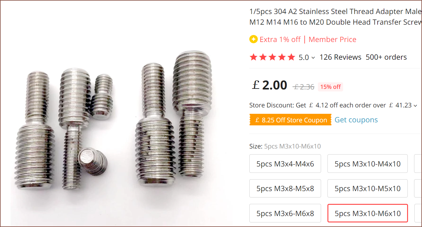
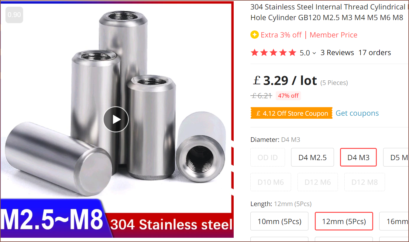
There are these in stainless:
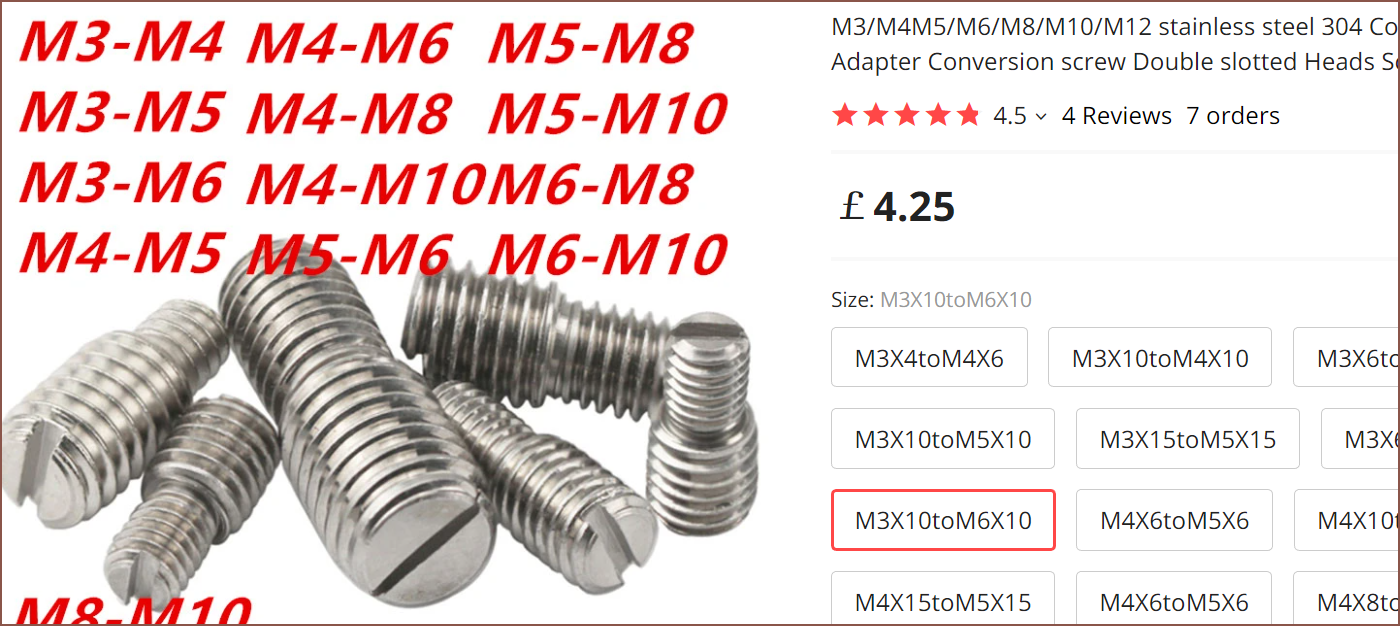
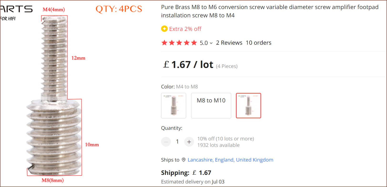
Now, if I have to use a 5mm bore, I'm not solutionless:
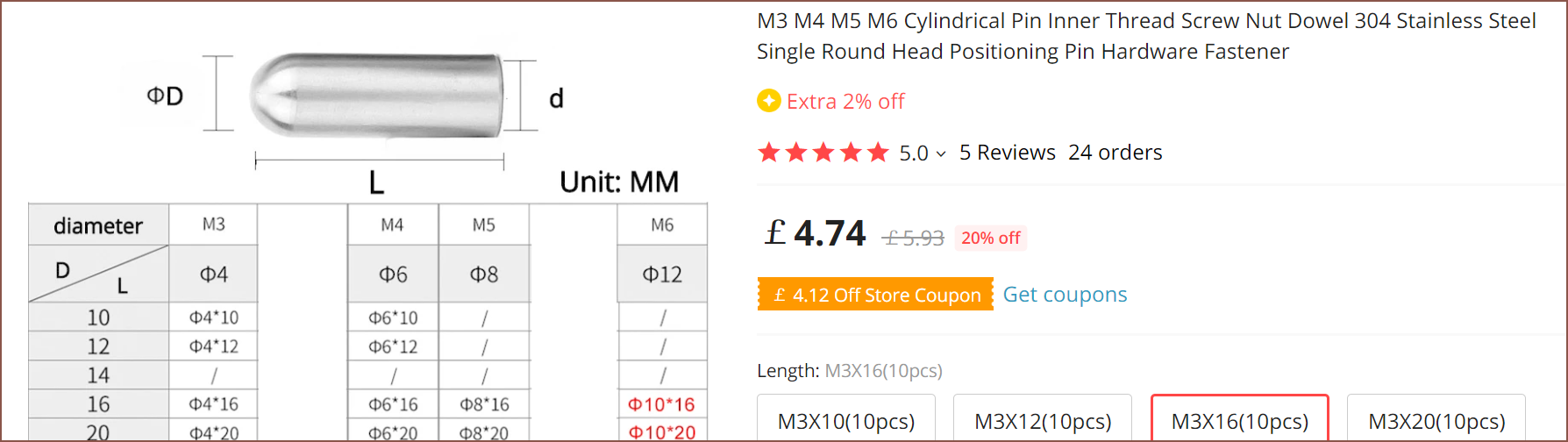
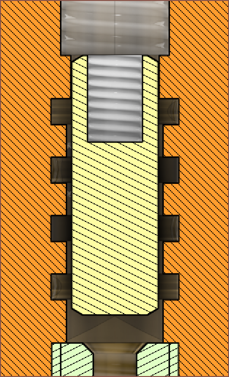
I could pair this inner thread positioning pin along with the above conversion screw. This is what the 12mm long version would look like:
I also wonder if the below solution would be acceptable:
It uses a 3mm hole at the top, allowing the tool to come in from the bottom ideally. 3mm Od x 1 - 2mm ID also exists, as well as 3mm throats, so it might be possible to actually DIY a custom throat for a solution.
[15:30] (playing different background music)
I've considered long brass inserts:
I've also found flat versions of the stainless steel pin things:
It turns out that the CSA between a 4mm and 5mm circle is >7mm^2. At the same time, since the internal grooves act more like cookie cutters than a traditional wall, perhaps this is not as important. I could always ask PCBWay if I can get a 4.5mm groove by reducing the depth to 0.7mm. That runs the risk of everything having to be a precision fit though, so it might be necessary to use a 4.1mm hole at the top to make sure the insert is centered.
[23:00] The 3mm hole edition won't work since I won't actually be able to tighten the internal thread dowel. I'm thinking of trying for a through hole of 4.5 - 4.7mm (and just go to 5mm if PCBWay says no).
I also started having suspicions that the grub screws I found were going to work, and it turns out that the E3D Cyclops actually uses a ball to seal:
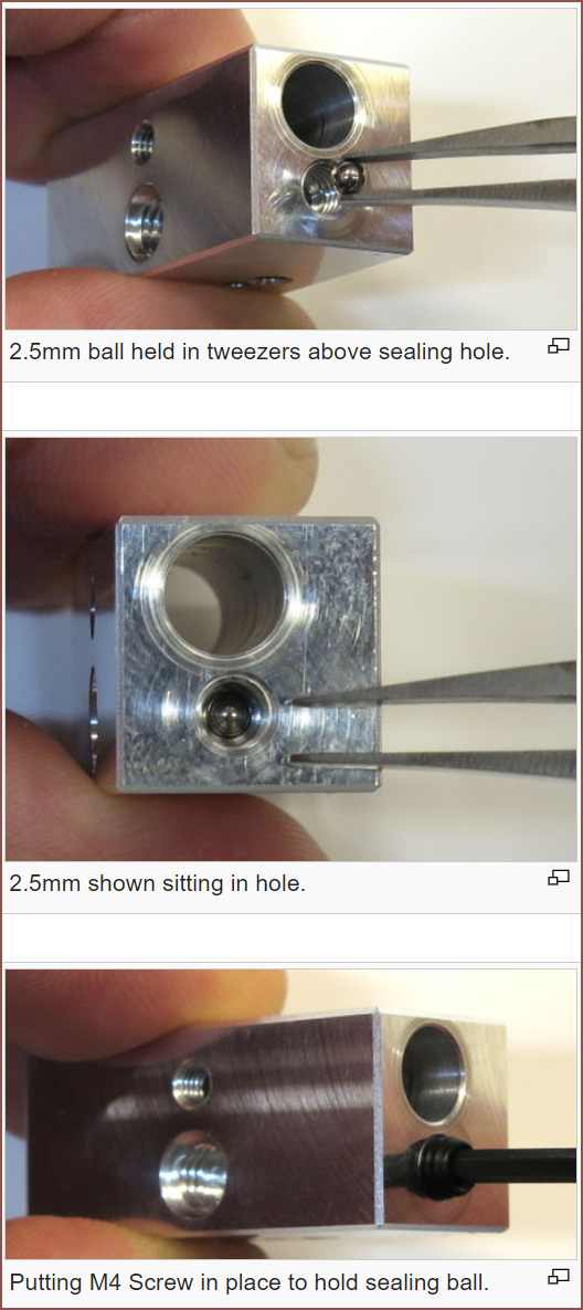
It turns out brass grub screws with sharp ends exist, which should improve the sealing ability:
Hopefully, I can use these for the cartridges too. The thermistor is also vertical now, as well as the across-flat dimension being increased to 33mm so that 3mm tapped holes can be integrated into the design.
[May 4, 08:00]
Looking at the start of this table, I should be fine with using the pointy grub screw for everything;
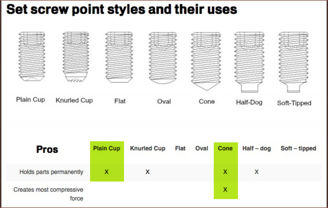
Source
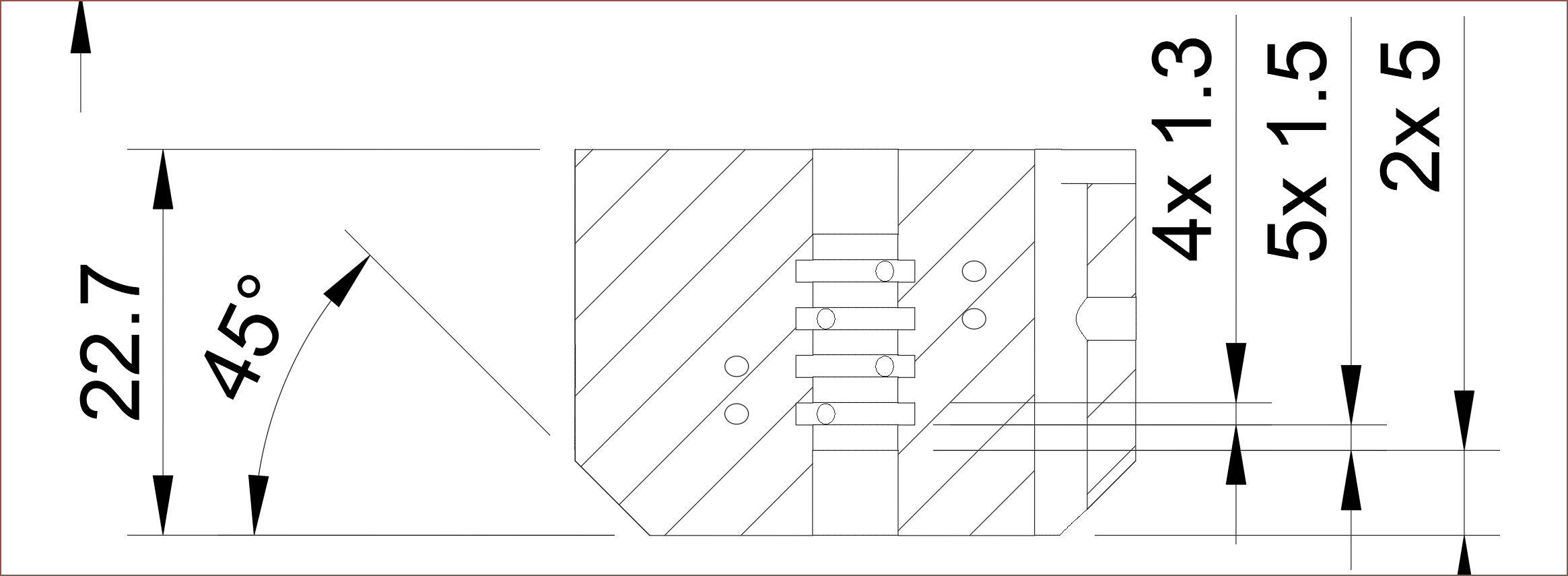
I've also gotten another email after sending my 4.6mm hole, 0.7mm deep internal groove file to them before I went to sleep:
Hi,

After communication with the factory, we have decided to produce
according to the hole size of 4.6. We do not charge any additional
fees, and your order can be processed. But if you place the same
or similar order later, the price will definitely be updated.

- PCBWay Service Team
My reply was a 5mm hole, 1mm groove fileset.
I decided that I was going to play things on the safe side since I shouldn't assume that the stainless steel pin, adapter and thread are all perfectly straight and centered, and a 0.5mm gap allows more margin for unexpectables.
Additionally, a 1mm groove will be easier for the material to flow around the center, likely aiding in even coating. I've also increased the internal groove height to 1.3mm to ensure that any small channel misalignment doesn't impact the coating geometry or cause a pressure imbalance.
Lastly, a 5mm hole is tappable to M6 thread, meaning that's one less tool PCBWay or others need to switch to to cut both. As Me In The Past has learned, if the thread isn't cut all the way, anything screwed into it will be stopped.
Everything looks good. Sending off the files now.
[11:30]
Hi,
We can process the files in the attachment.

- PCBWay Service Team
[8 May]
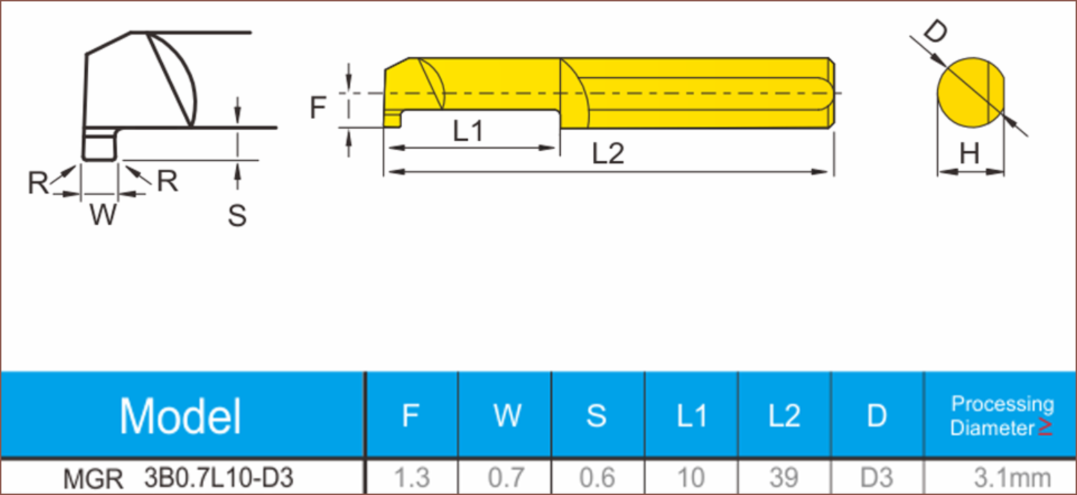
I've finally come across a listing that gives the needed information about the MG series of micro internal grooving tools:
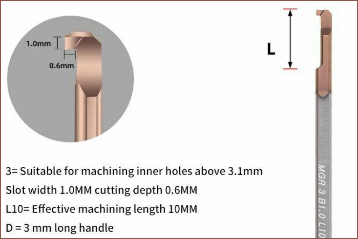
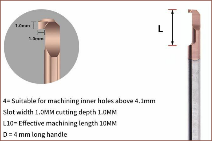
This is likely the reason why a 5mm bore is required; MGR3 can only cut 0.6mm and MGR4 can cut the full 1mm.
Discussions
Become a Hackaday.io Member
Create an account to leave a comment. Already have an account? Log In.