 kelvinA
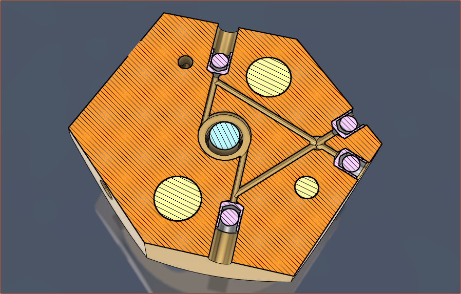
So, understandably, the technician isn't going to spend another 24 straight hours making another heatblock prototype, especially with first years now showing up to university. He believes that an assembly line could probably make them by the 100s, but creating a one-off is tough. He did note that the small side threads were the toughest part of the design to manufacture. He also warned that the surface finish needs to be sufficiently good to create a seal with a ball bearing, which is the kind of thing that E3D likely has ommitted from their drawings (or I just never saw them because the drawing was hard enough to read already). Lastly, all the technicians and I had a short brainstorming session of what can be done to seal the drill bit entrance holes.
Thus, in gearing up for a round 2 with PCBWay, I wanted to see if I could do more than the solution I thought up a few days ago.
For starters, I found a post on the reprap forum where someone created a silver heatblock and observed that it got to temperature in 1/4th the time. Looking up the specific heat capacities of metals, Aluminium is 921 units and silver is 238. Brass is 402 units so I've gone back to that.
Then I was trying a few different search terms and stumbled on this:
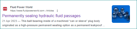
It turns out that there's a new invention between when E3D made their Cyclops in 2014 and now. And the best part is that I found it on AliExpress:
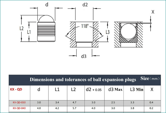
As you can see, they use the standard 118 degree taper that common drill bits create.
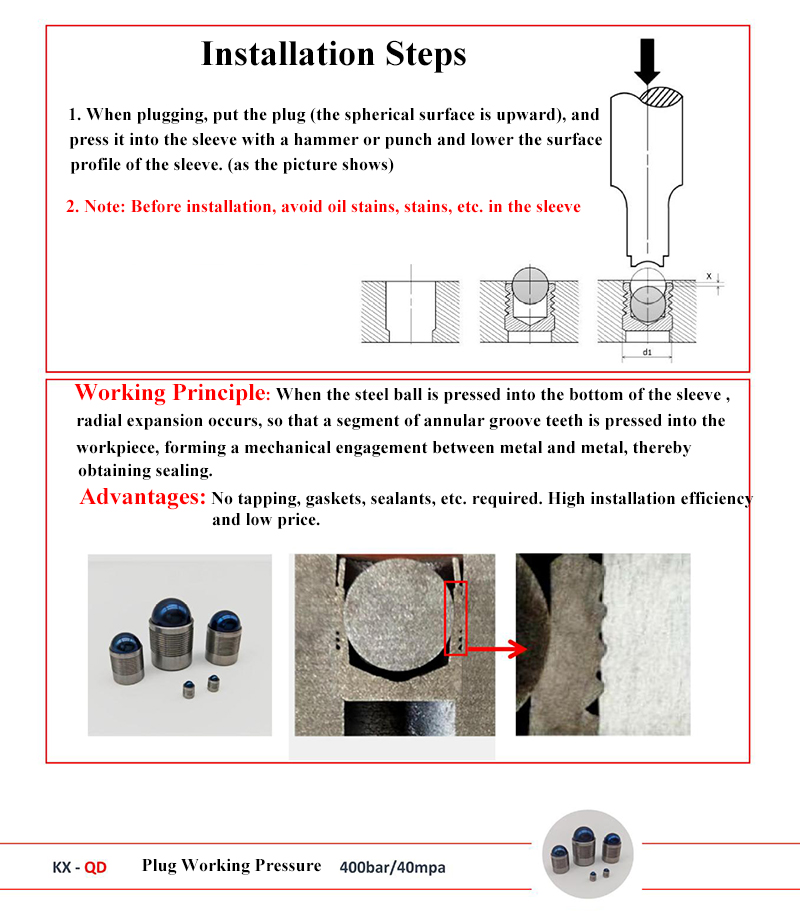
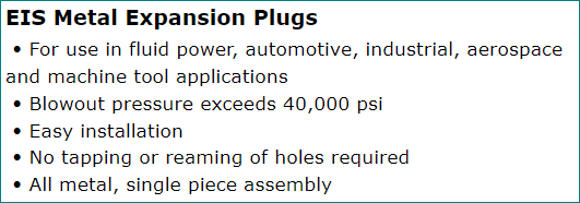
This image here shows how the thing actually works. When I first saw it, I was under the impression that the ball would be doing the sealing and that it's just a combined ball bearing + grub screw. This is when I sat back in my chair, breathed out and uttered "It's a solved problem...". That was, until I realised that it listed that the max working temperature was 150C. I'm don't know why, but I can only guess it's something like the material or perhaps trapped air? I did some searching and some manufacturers protect their sleeves with zinc, a material I hear doesn't work too well at FFF 3D printing tempteratures.
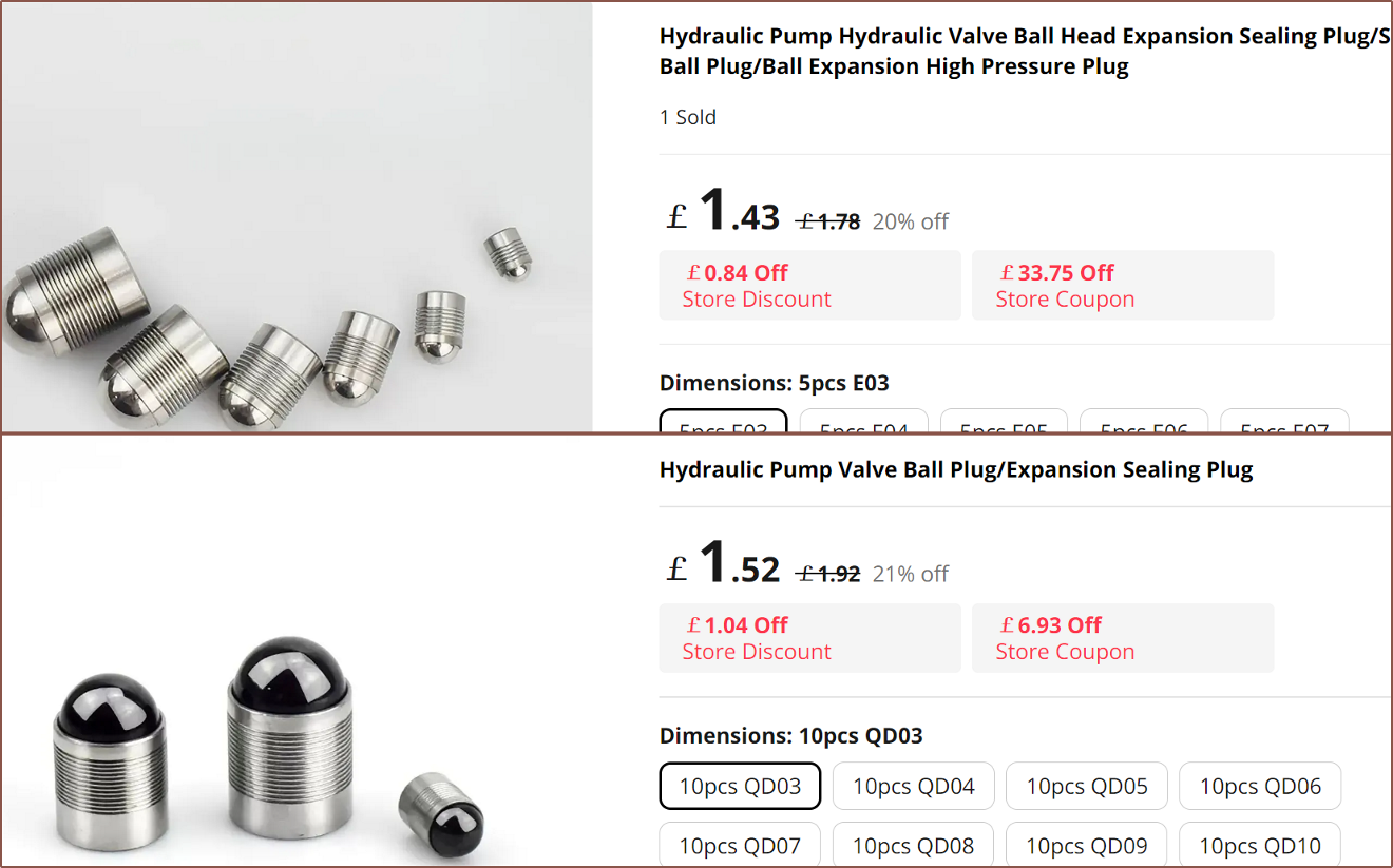
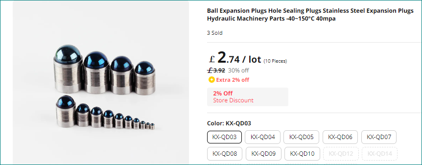
There were 2 other kinds that I found online. They didn't list any temperature range, but the top one is made with stainless steel for both the ball and the sleeve so it's probably OK to use.

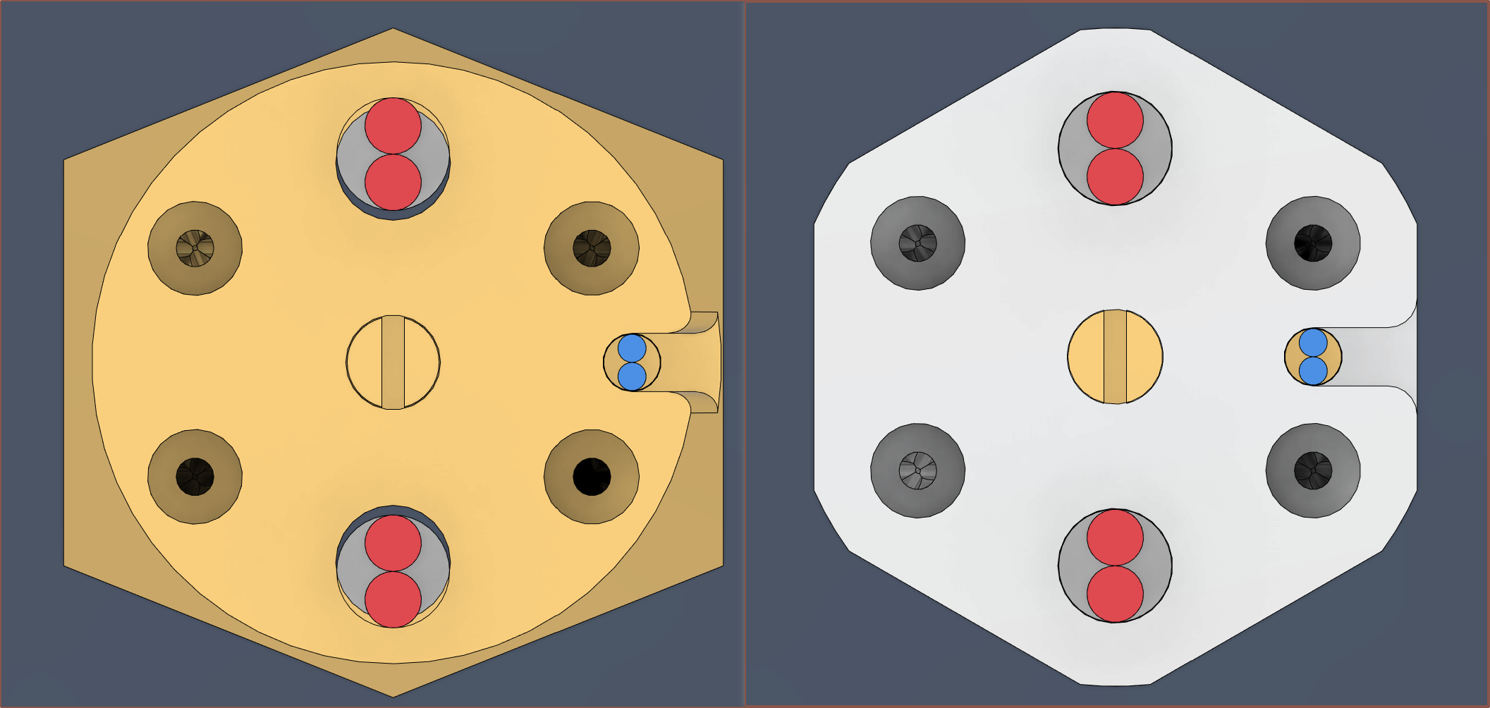
After that came the trail and error process of trying to incorporate the off-centered inlet approach I talked about a few logs ago. I hypothesised it and if I'm going to be spending another $70 I should at least try and validate the hypothesis while I'm at it.
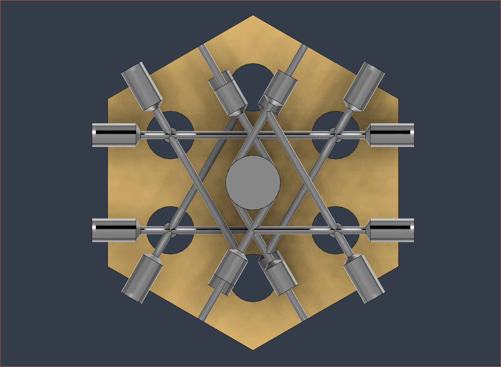
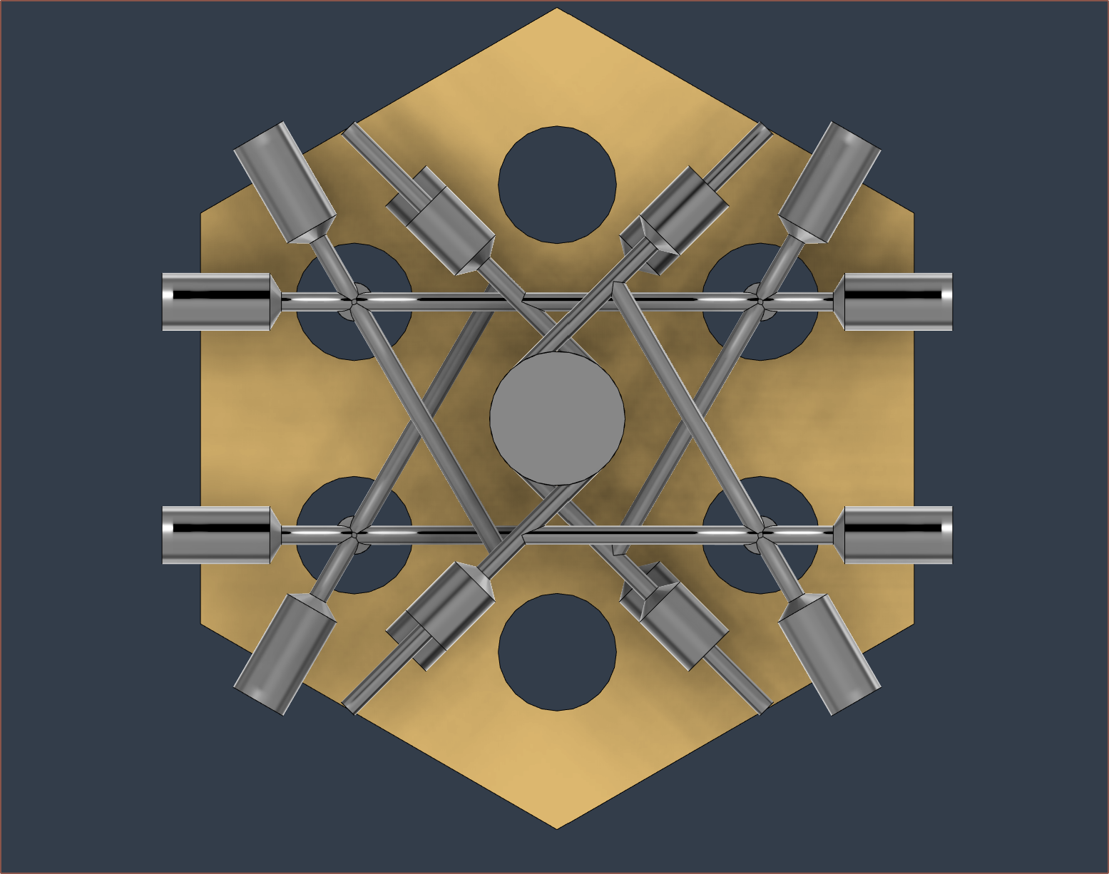
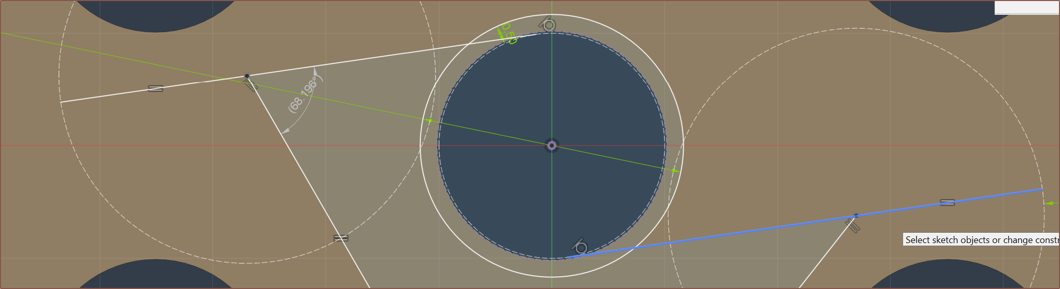
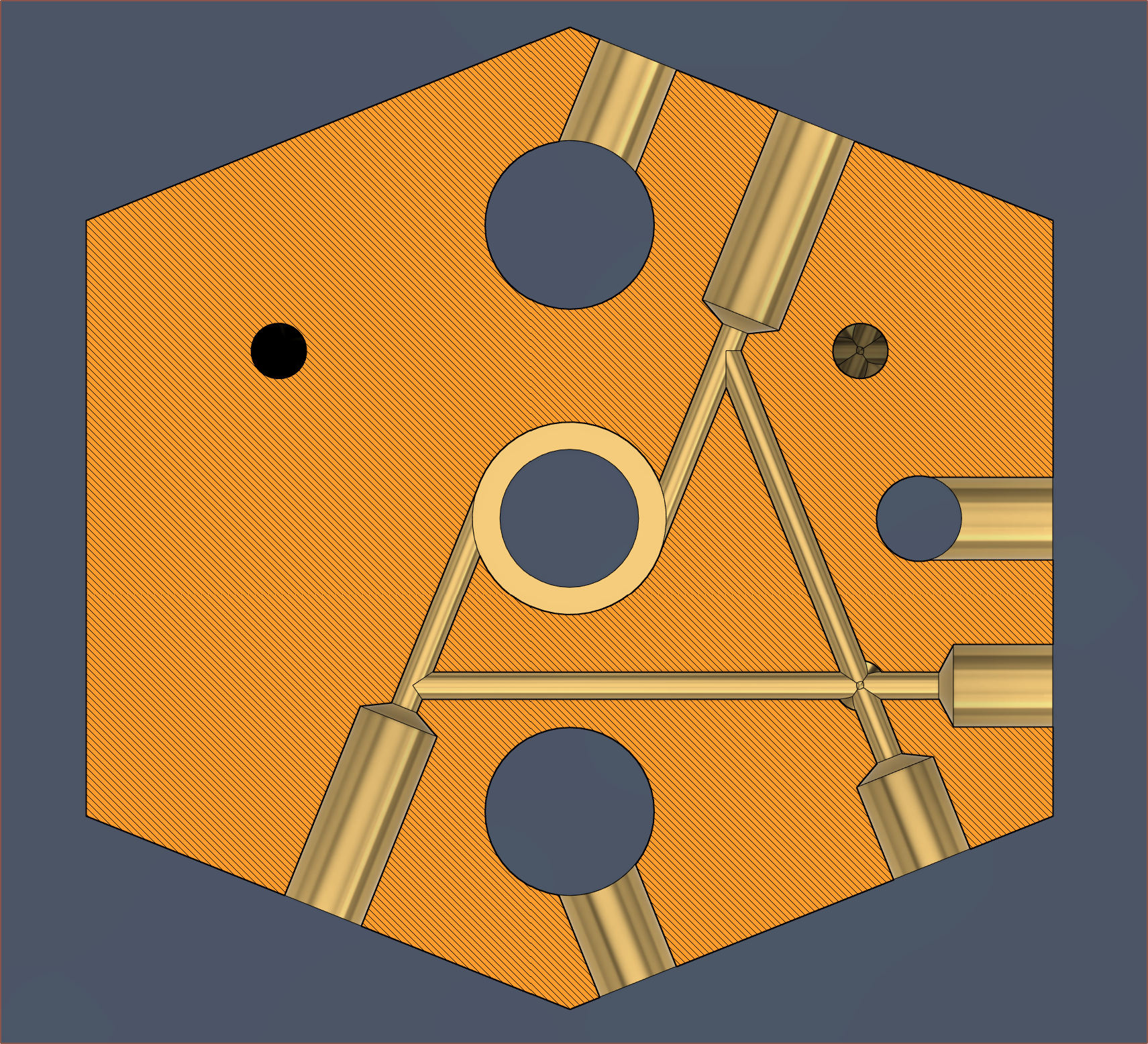
And there I had it: a solution. I'm expecting this squashed hexagon shape to be milled out of a larger, rectangular block. I'm also hoping that the slight length mismatch between the 1mm paths won't cause noticeable pressure imbalances. It's very slight -- only 3mm difference.
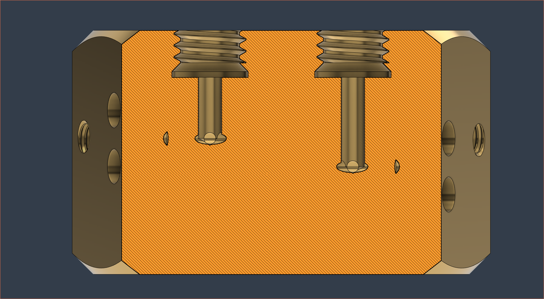
I'm expecting PCBWay to have more tooling, so I've shaped the threads to use the tools I discovered last log. Lastly, I do a 55 degree revolve chamfer instead of 45 degrees:
The dimensions of this new one and the one that was fabricated are rather similar. I'm wondering if I should fillet those sharp edges though. It's probably fine.
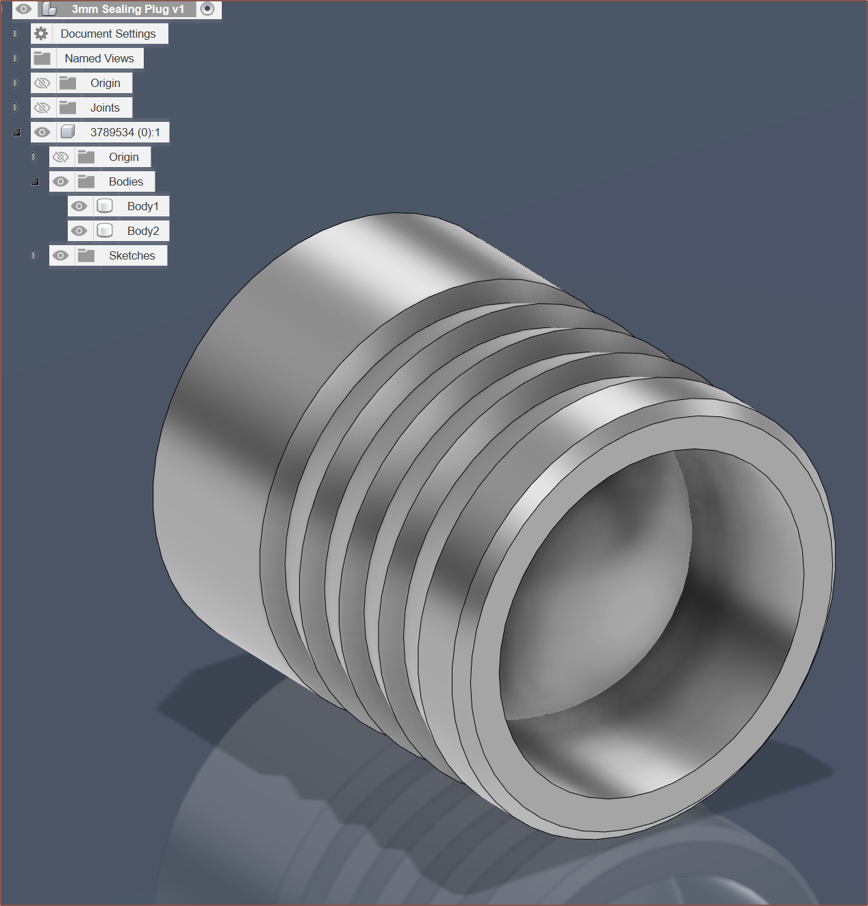
Next I found the most similar CAD model I could and modelled the ball inside the sleeve (as they all are modelled with the ball in the position as sold) and then tried the new Duplicate with Joints feature.
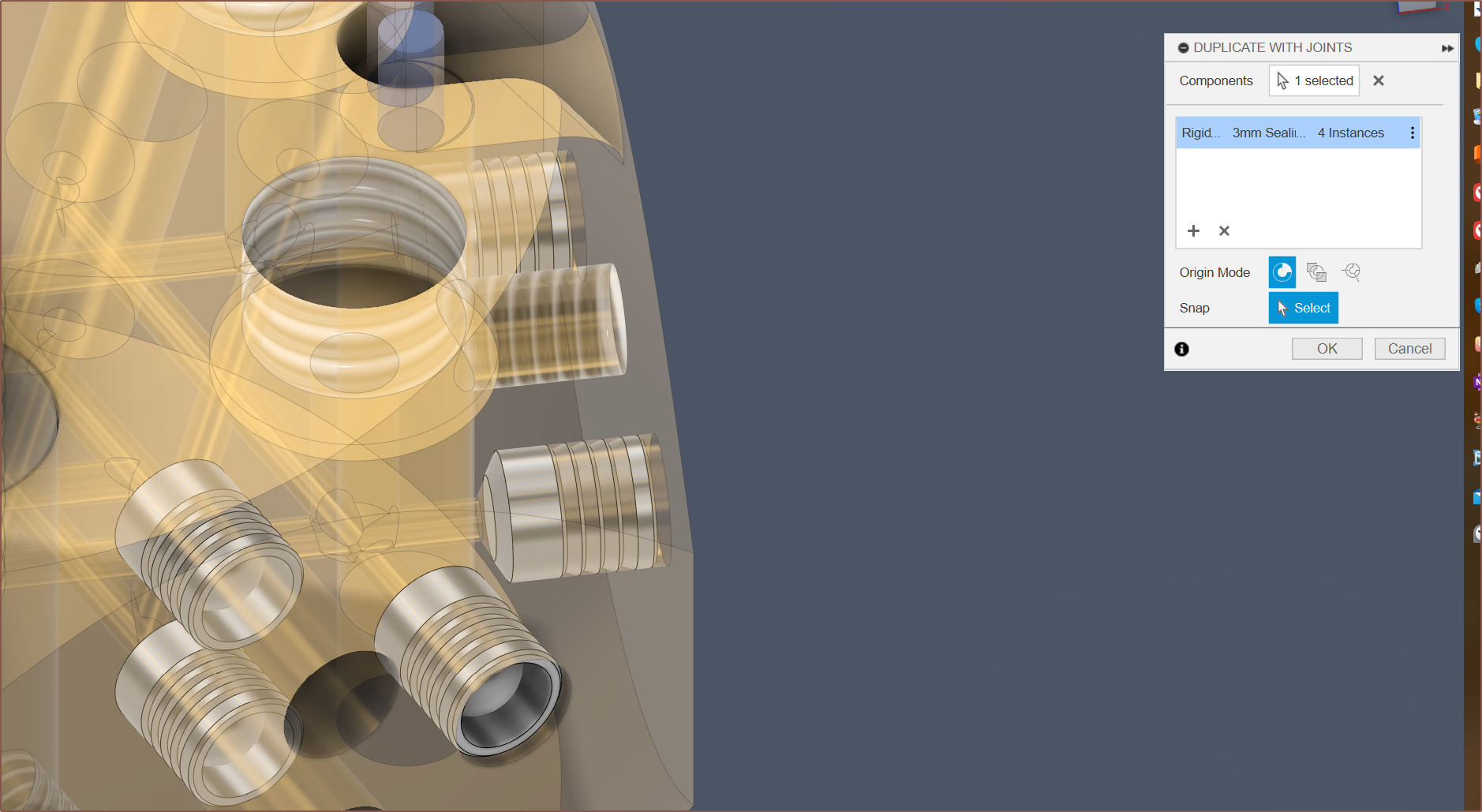
I'm probably going to have to back over it manually like what I did in the past since the tool doesn't use parameter values but just copy-pastes the absolute value of the joint. The feature also fills the timeline more than it needs to:

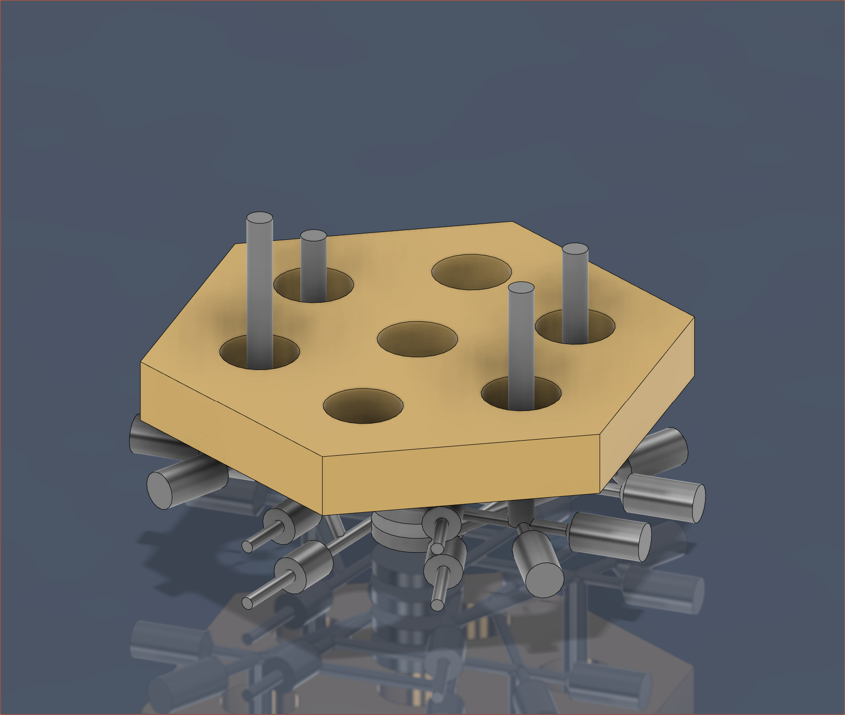
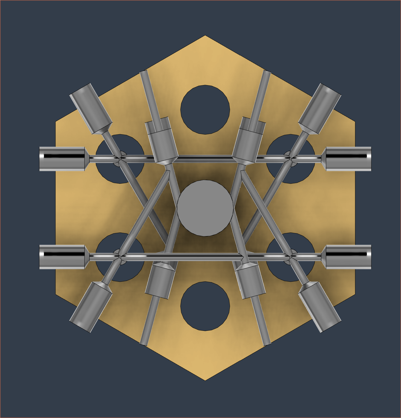
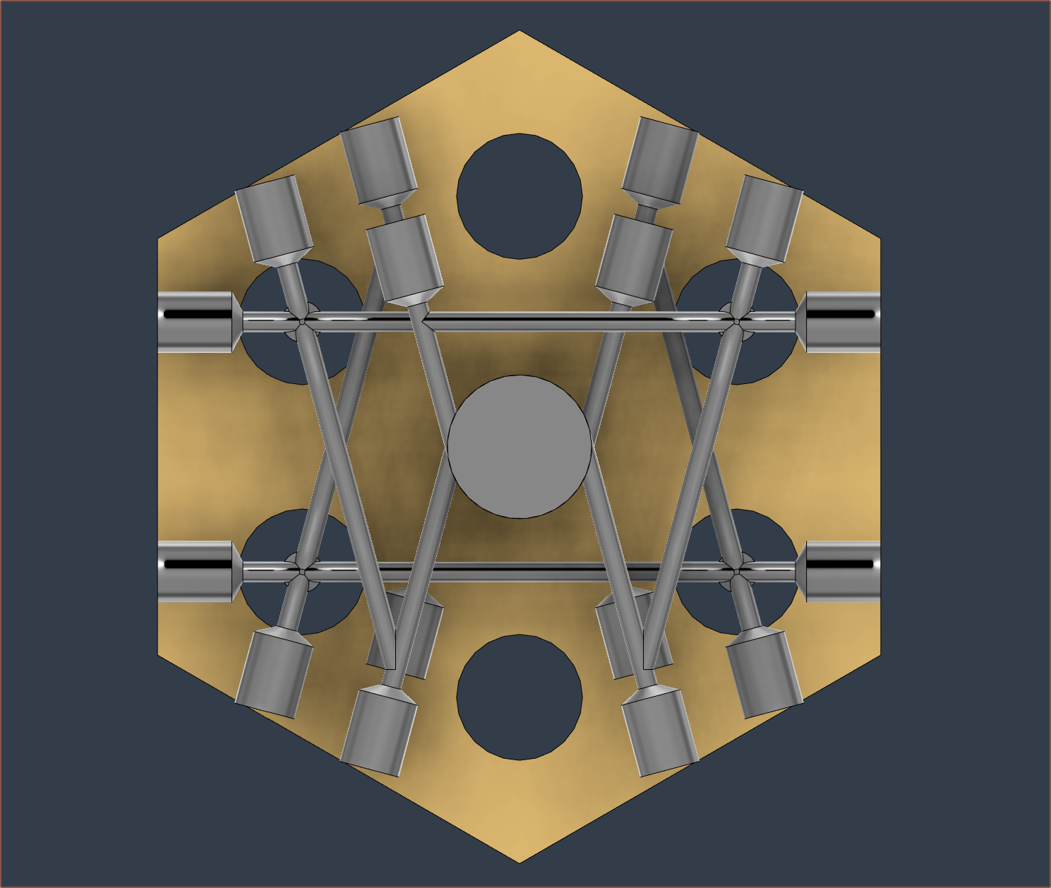
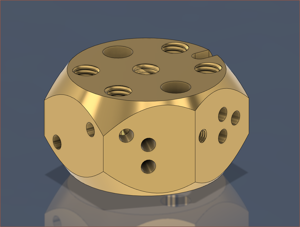
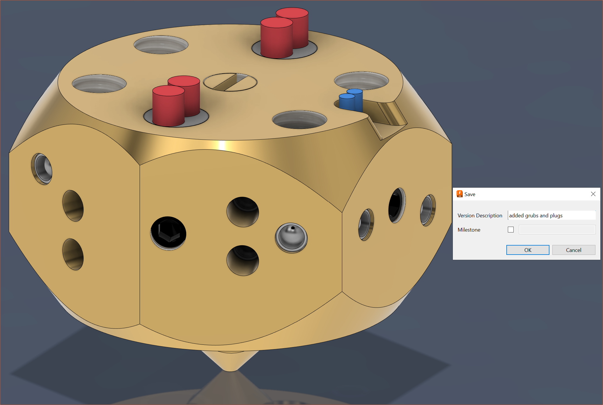
Anyway that's the new block and where I've got up to. Here is what the entire block looks like:
Now to see what PCBWay thinks of it.
Discussions
Become a Hackaday.io Member
Create an account to leave a comment. Already have an account? Log In.