 kelvinA
Or 9 in 1 out if the centre is used.
I know it looks complicated, but it's not complicated.
Modelling
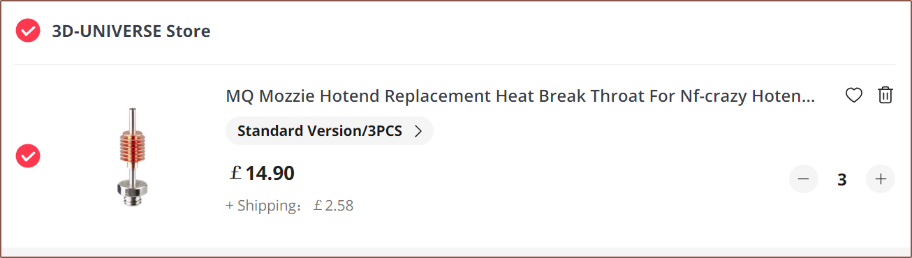
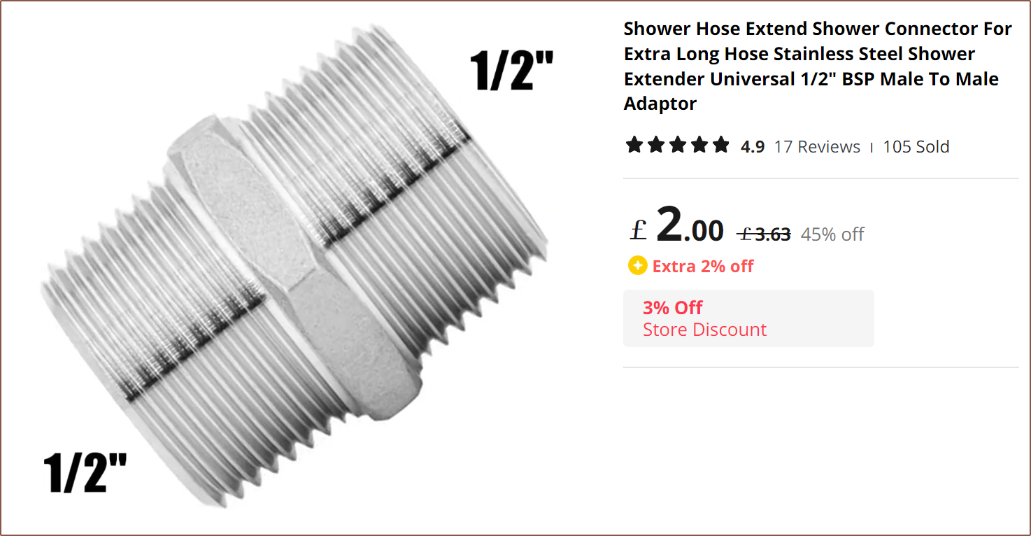
So, as I've read other engineers do, I wanted to see how far I could push the concept. The Palette 3 Pro had more inputs than the Palette 2 and Nozzleboss' 3rd version hotend had 1 more input than the 2nd, so it should be a natural progression to try for more inputs in the next prototype. Wanting to at least get to parity with the 6 in 1 out hotend from deckingman, I started trying to solve for that. First, I found some relatively affordable heatbreaks, chosen because they have a hex-nut geometry that I can use to tighten them and prevent leaks.
 Then I spent some hours on the redesign:
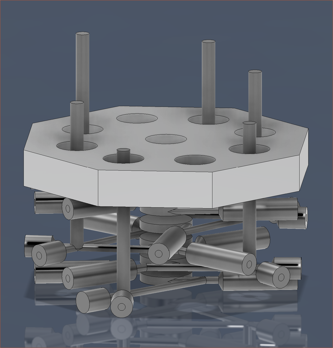
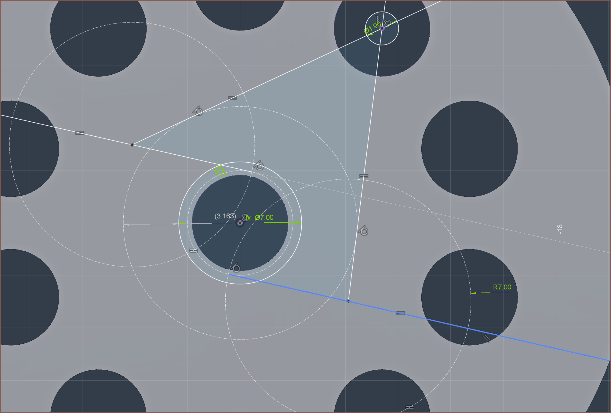
It was ok, but none of the drill paths lined up and I was wondering if the optimum solution is a power-of-2 kind of thing. It's only when I started trying to solve for 8 that I realised there was a dimension I didn't know was there:
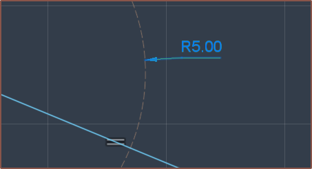
So there probably is a 6 input solution where both paths are the exact same length, defined similar to the below sketch:
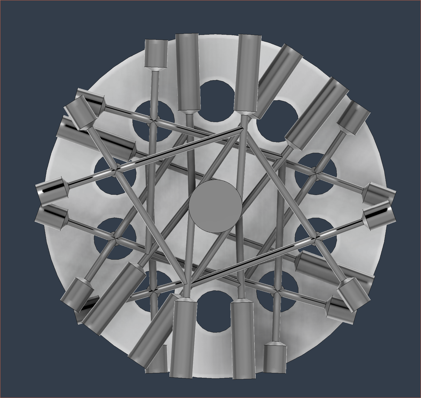
This is one of the first permutations. Solving this problem visually is a lot more like the Polysphere game, where I'm just rotating the channels in different ways and configurations to find a solution.
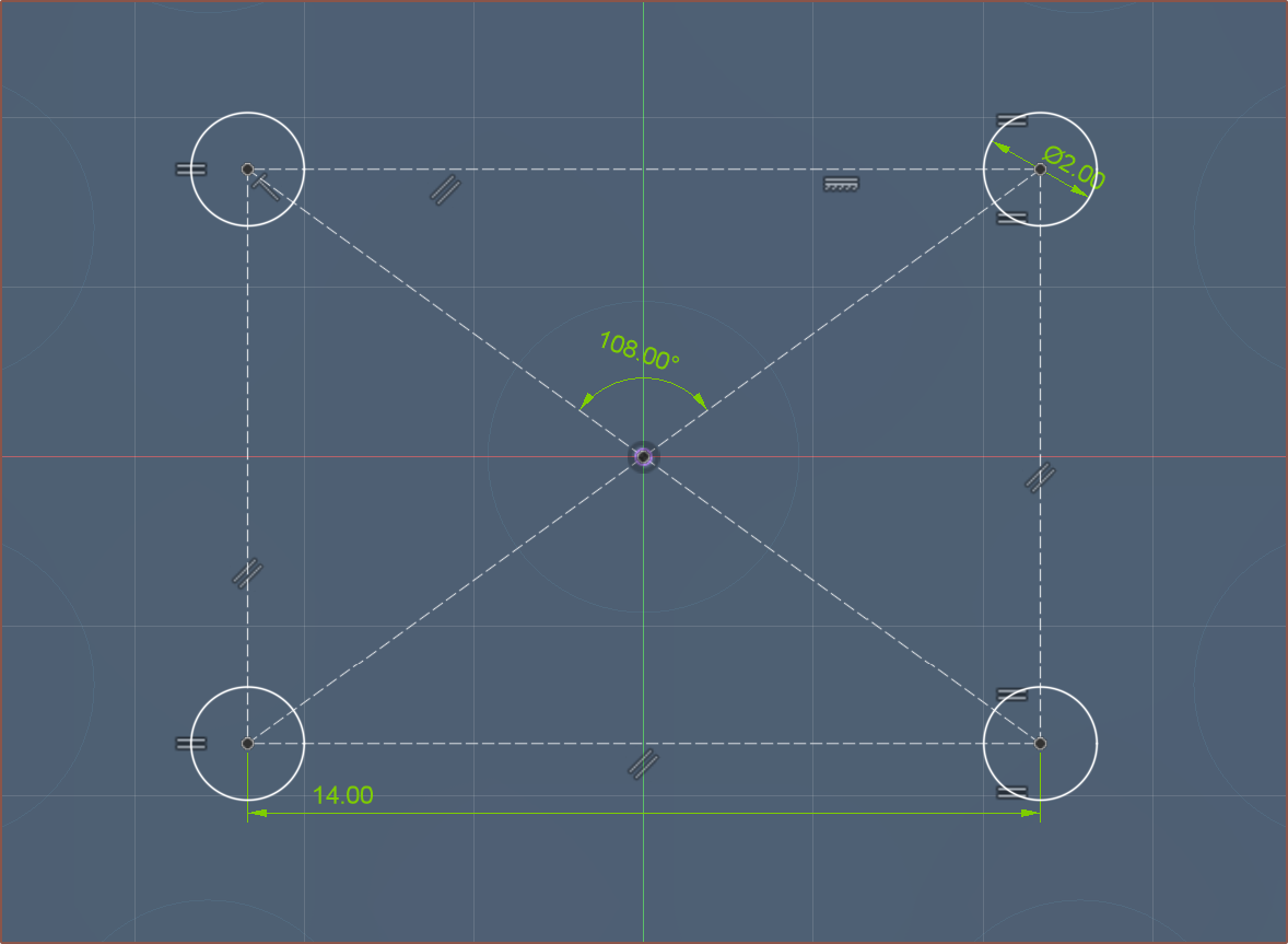
Eventually I got something promising:
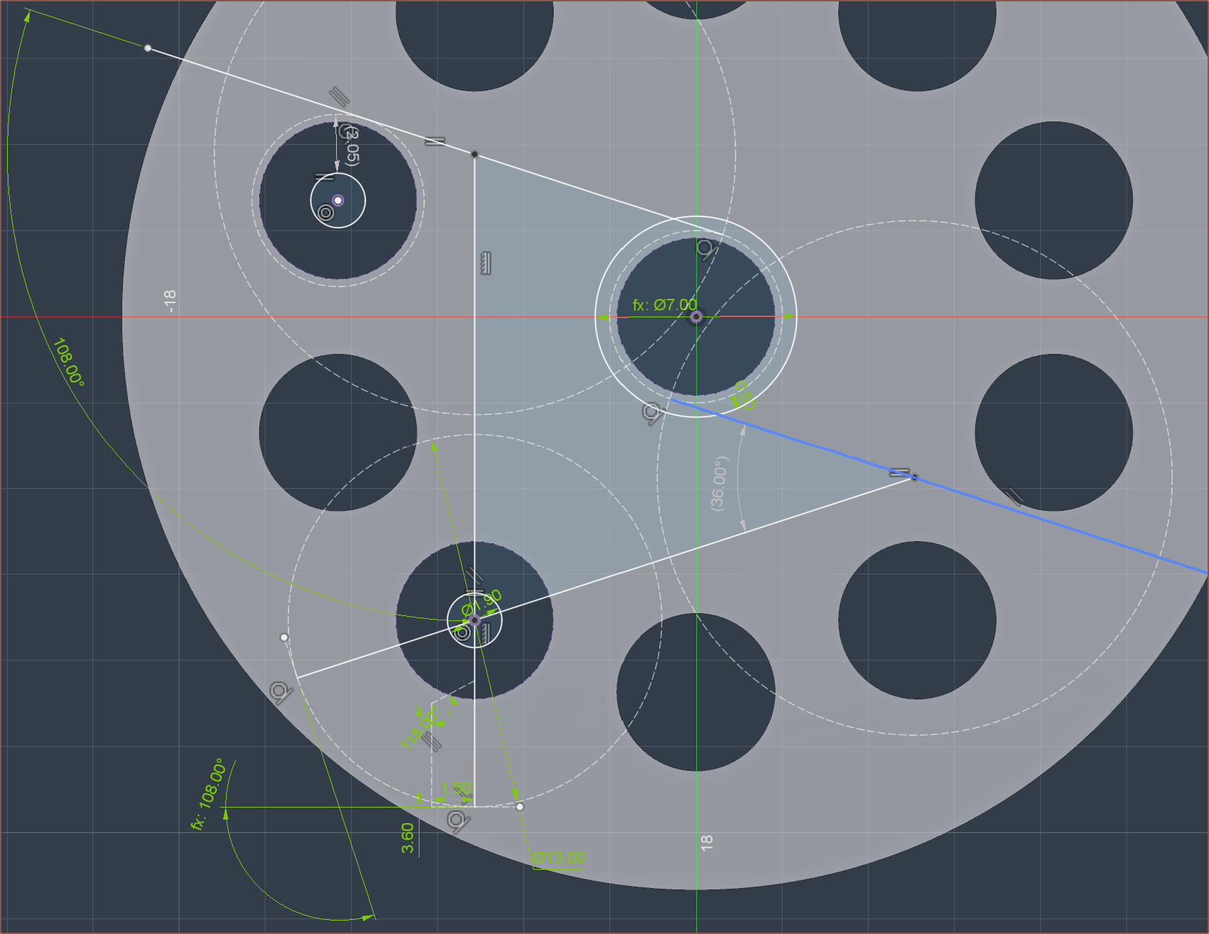
By making 2 angles 108 degrees (a multiple of 18, as 10 * 18 = 180) and having the paths be Standard (S). Mirrored (M), S, M, M, S, M, S, I got this:
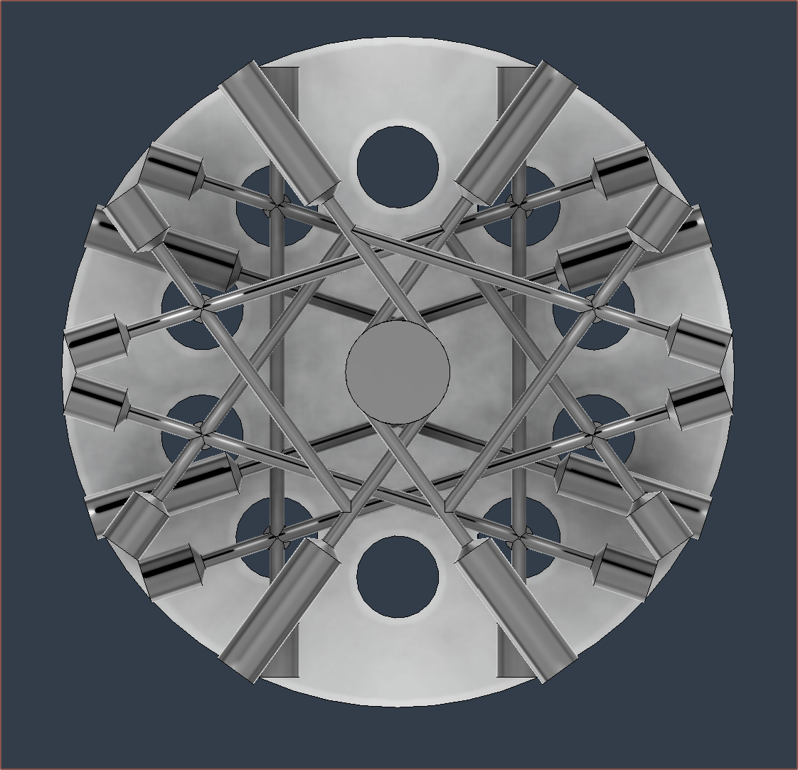
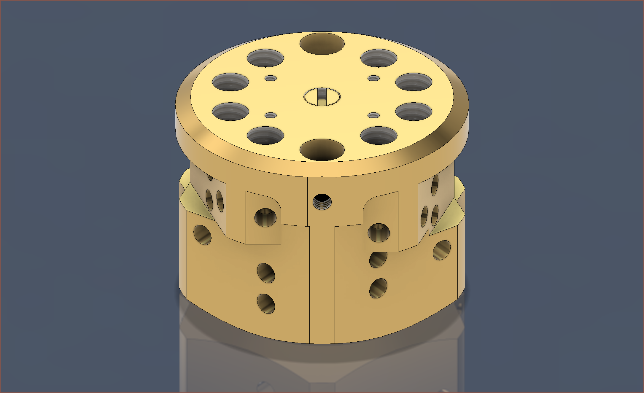
Then it was a case of extruding the flats and push-pulling some faces:
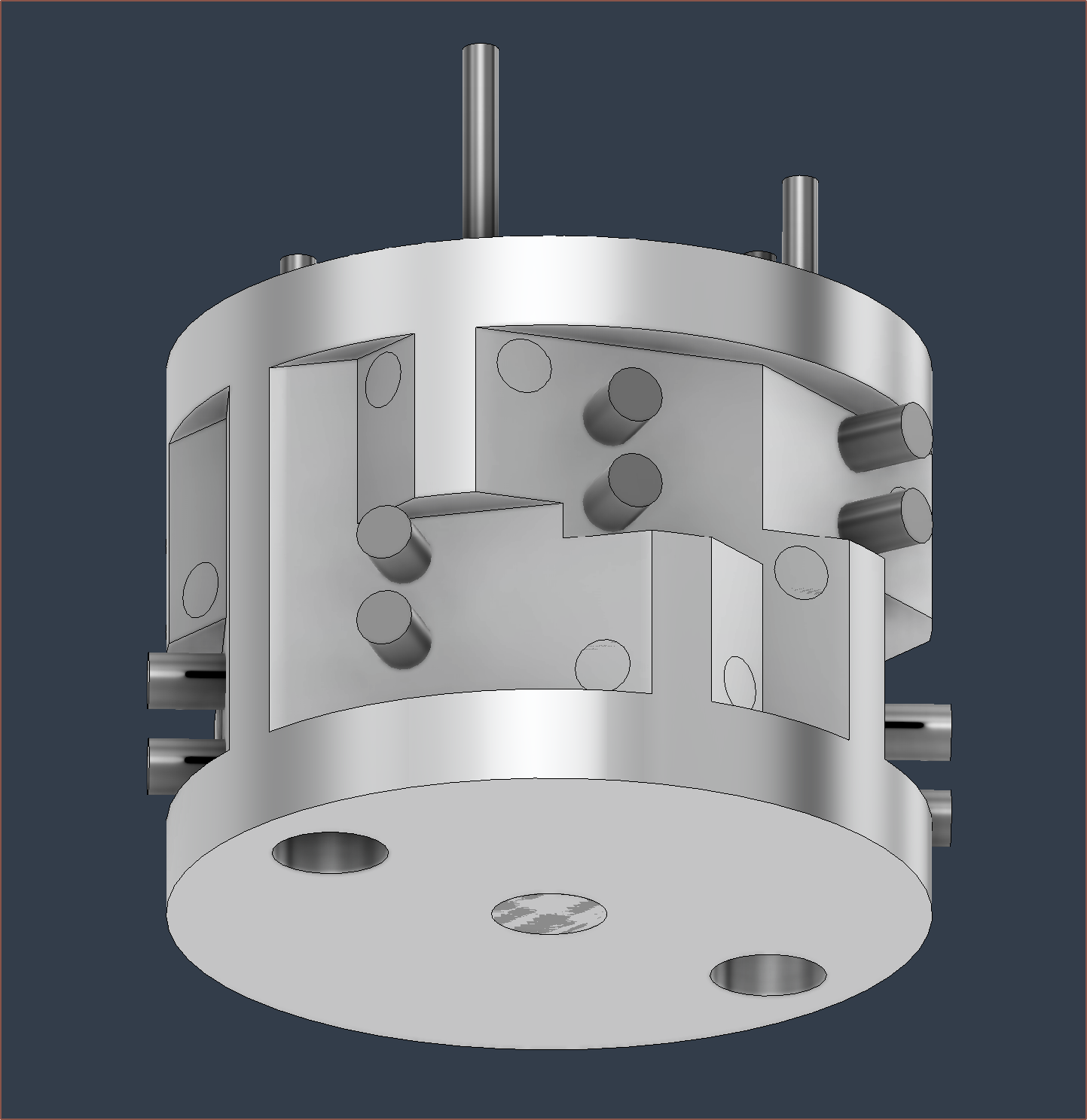
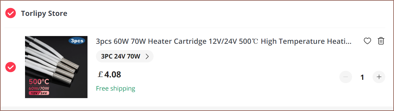
The block is 30.4mm, but 30mm cartridges are rare. The only ones I could find were 40W anyway, so I just used 20mm cartridges and the hole is 20.1mm.
For the grub screws, I planned to use M4s since I can't remember having a single issue with them, unlike M3's. This requires an outer diameter of 42mm.
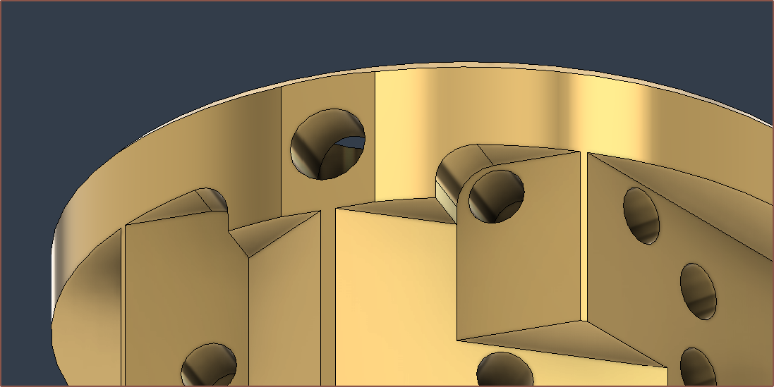
Also notice the fillets on the side. This is so that the endmill bit can reach everywhere, and I assume that the larger the fillet, the larger an endmill can be used and thus the faster the faces get milled.
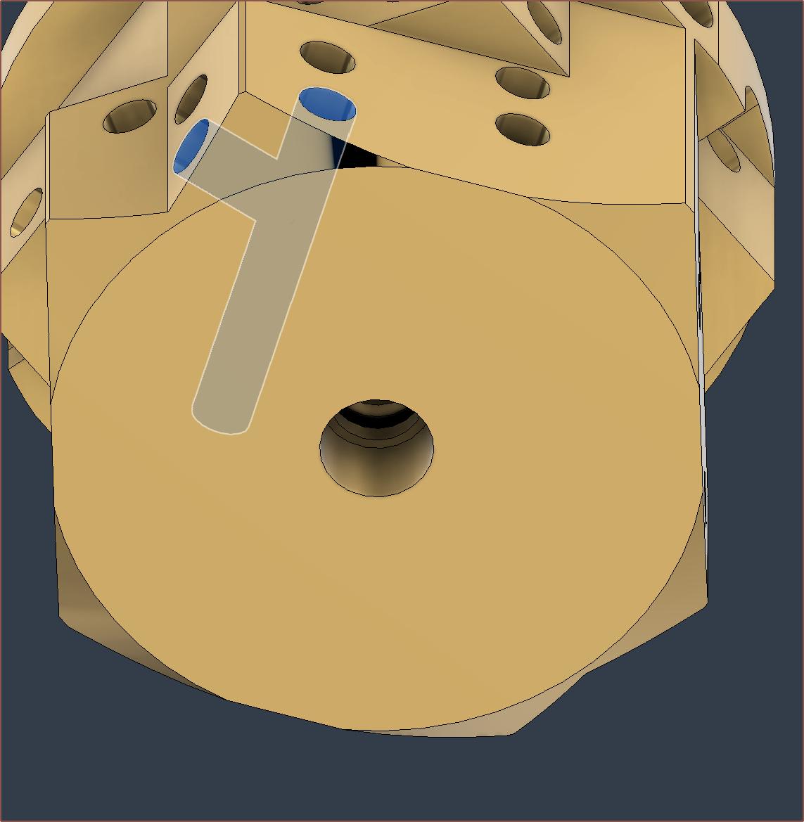
Partially to reduce the amount of molten filament inside the heatblock and partially to increase the minimum wall thickness between the vertical paths and the plug holes, the vertical paths are now 1.8mm.
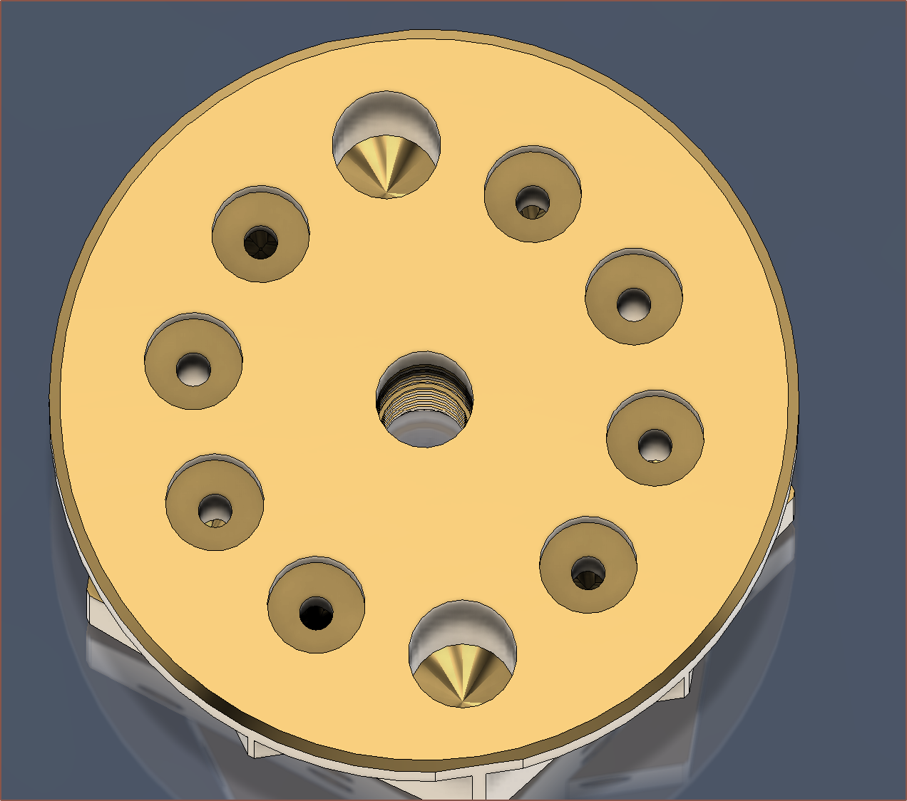
Next are the M2s.
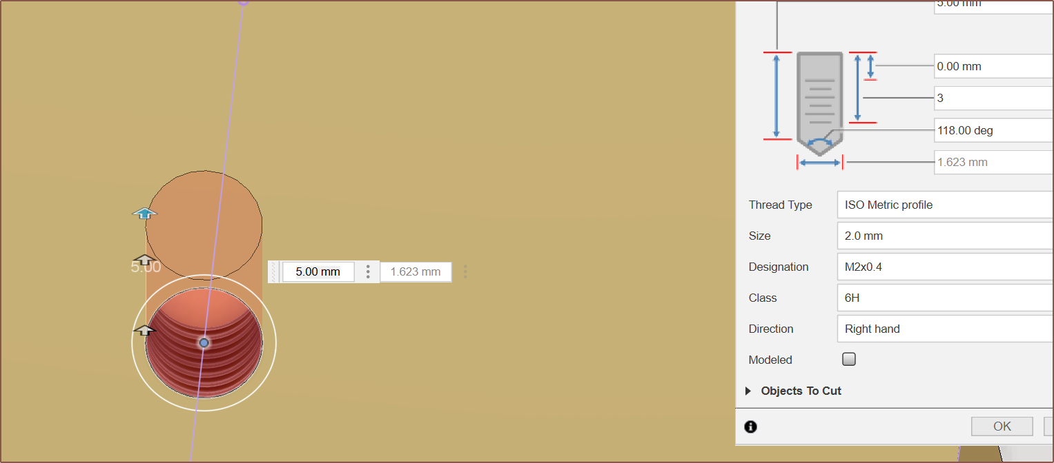
I found out that the Hole tool is very well featured and even allows me to set a specific depth for the threads.
 It slightly intersects with the thermistor hole, but I'm only planning to screw into a max depth of 3mm so it should be fine.
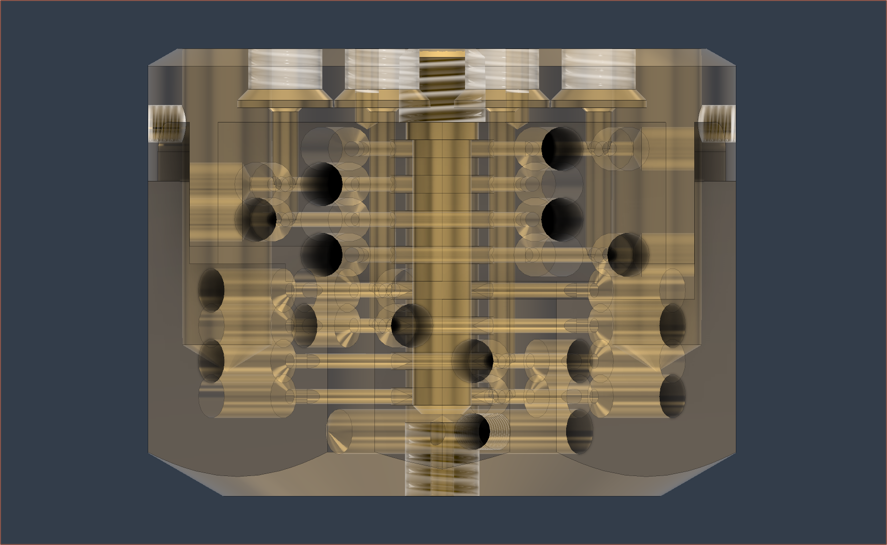
The main target mass of this 8+1 in heat block was less than 2X of the 4+1 in, which equates to 280g. An additional target was 250g. The design has surpassed both targets with a mass of 240g.
Next Steps
With 8 inputs, the situation with inactive inputs is now even more of a concern. The strategy of a lower combination temperature and separate print temperature is likely one of the better ones, though ideally there'd be some way of blocking off unused inputs.
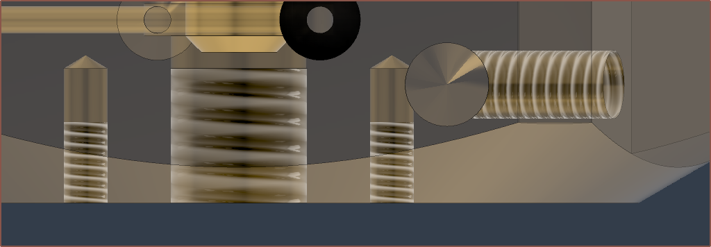
I'm most likely going to have to design another part that looks like this but for M6:
Alternatively, I could swap out the bottom M6 for an M7 so that I can use this part and just lathe down the copper side:
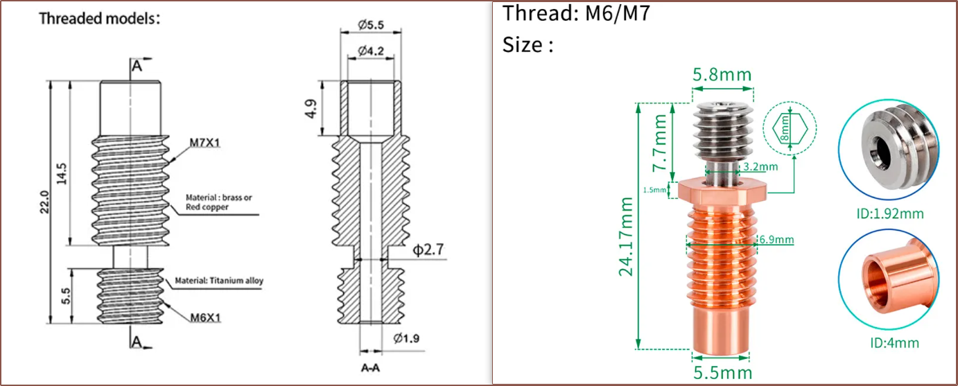
(A 3rd option could be doing the same as the 2nd but also reducing the M7x1 to M6x1)
Edit 1
I did some research on ball plugs, which can work up to 200C, but I'd have to integrate it somewhere where the filament is already molten.
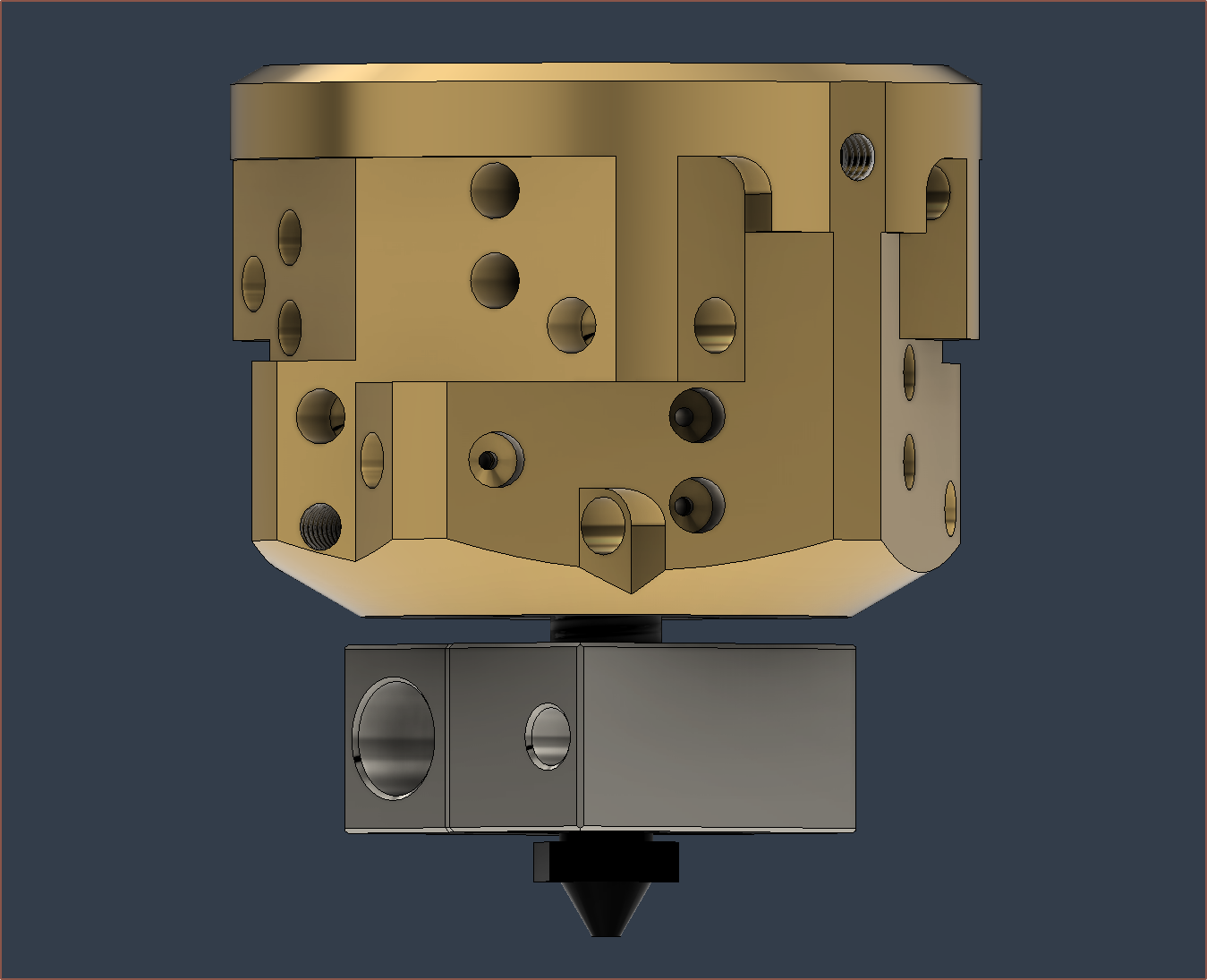
Hopefully, with a 2mm gap and the pitch of M6 being 1mm (thus, a 360 degree rotation translates the block up by 1mm), I should have enough adjustment space to get the additional block lined up to the M2 bolts, and a 1mm air gap between the two blocks.
Discussions
Become a Hackaday.io Member
Create an account to leave a comment. Already have an account? Log In.