 kelvinA
So I've had the main sketch ready to go for a few days now, which has unexpectedly become an eliptical shape when trying to minimise the size whilst still taking constraints into account. The main constraint is that I want this hotend to be able to mount directly to printers that use 2x M3 bolts spaced 14mm apart and popularized by Creality.
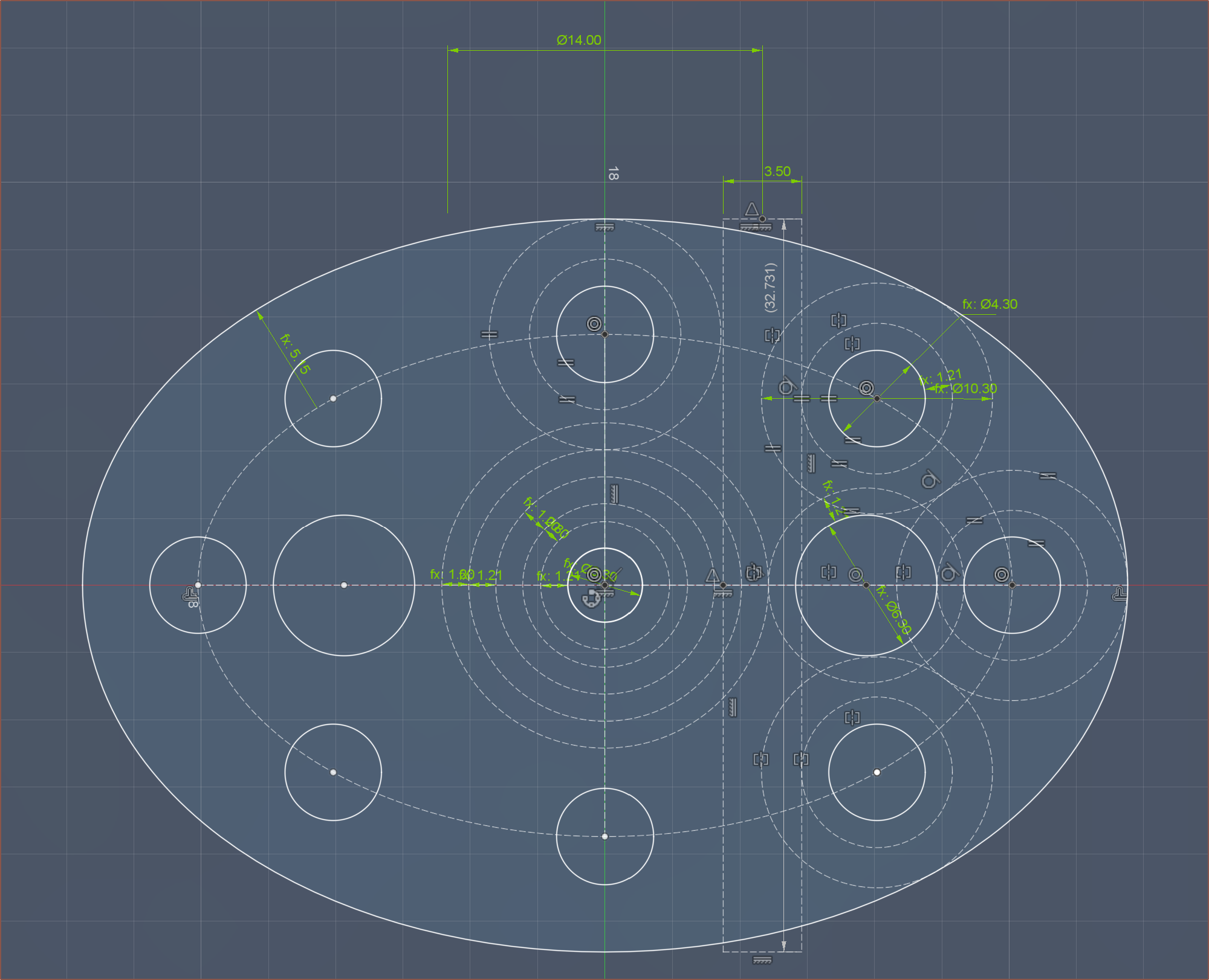
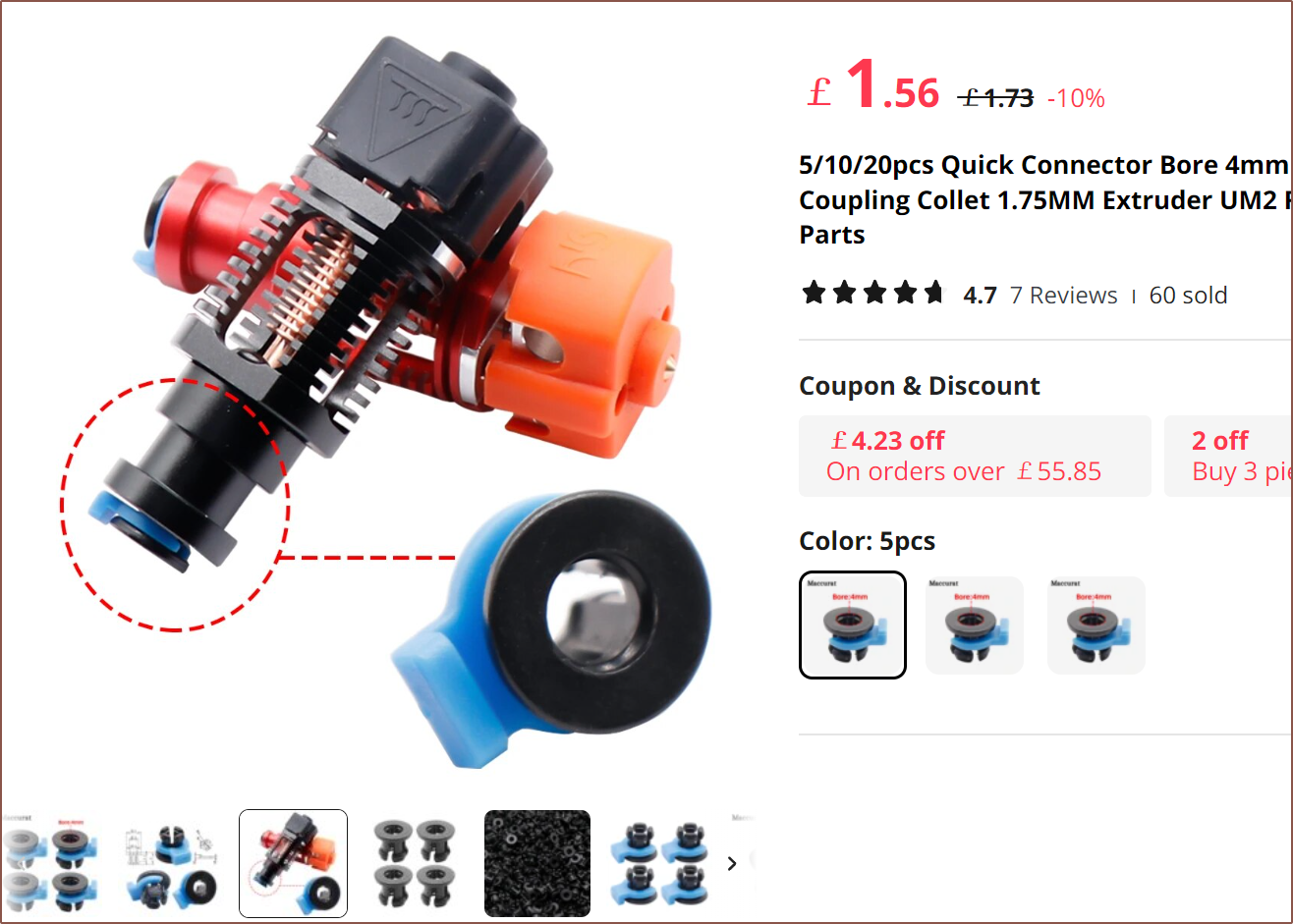
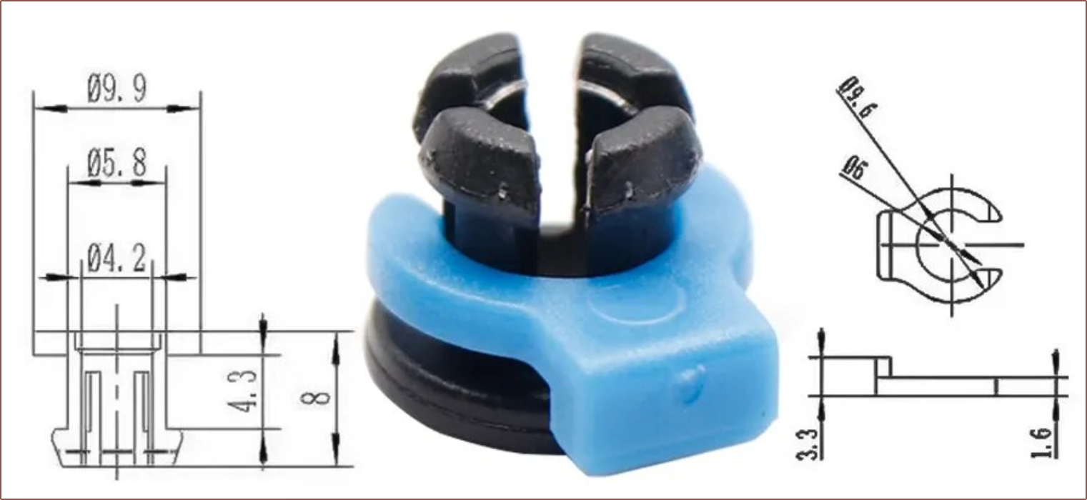
Now, other than that mounting constraint and the constraint from PCBWay that recommends that walls are at least 1.2mm, the method of holding the bowden tube in place dictates how compact I can make the unibody coaxial hotend. Until I looked into it further, I was planning to use something I believe are called "bowden collets":
I tried and failed to find out what internal geometry I should use on for the metal print, but looking at the drawings of the collet and plastic clip, I was thinking that I could model a good guess.
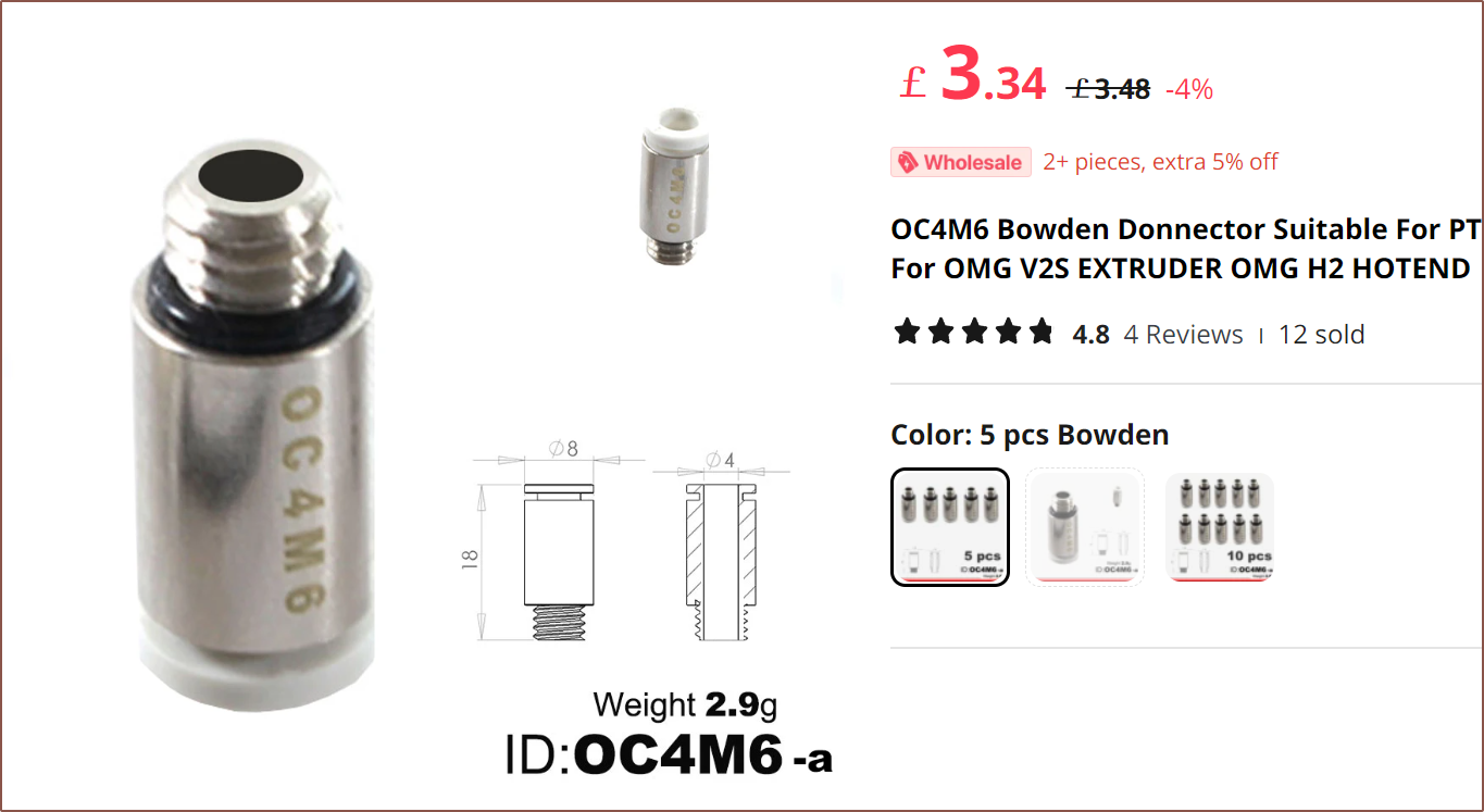
The thing was that I was also considering this coupling as it only has a max diameter of 8mm instead of 10mm for the collet:
Unsure, I started researching since the bowden holder determines how large or small the hotend can be. I then found this video:
This is when I remembered all the ways a print could have reduced quality or fail because of something to do with the bowden tube. It's already bad enough with 1 input, but my decimal odds of a problem are much higher when there's 8 inputs that all need to work together. I looked onto Reddit and the comments in this post seem to echo that a compression fitting is the best option for this application.
The first potential option I found was this:
Looking at the below video, it seems that there is a version that uses 1/8 BSP threads that are usually used with Creality heatsinks, and the hex doesn't look like it passes over the edge of the heatblock so I can probably assume that a spacing of 12mm between inputs would be required for this fitting. Additionally, some light drilling is required to allow the PTFE to pass through the fitting.
Now that still sounds like there could be a more efficient way in there -- one that doesn't require drilling and screwing the threaded part and then screwing another part ontop, and perhaps requires less spacing between input channels.
Such a solution actually may exist.
I found this fitting and then was able to find a very similar 3D model on GrabCAD (click the image to go to the source):
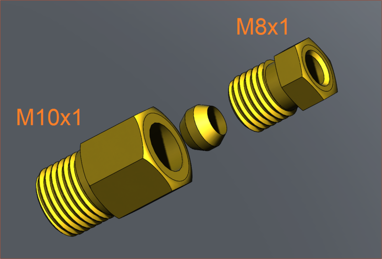
This allowed me to be able to see inside. I lowkey pine for the day when AliExpress, some day in the future, is some VR digital marketplace and most products have 3D models instead of today's task of looking at 2D images and hoping for the best.
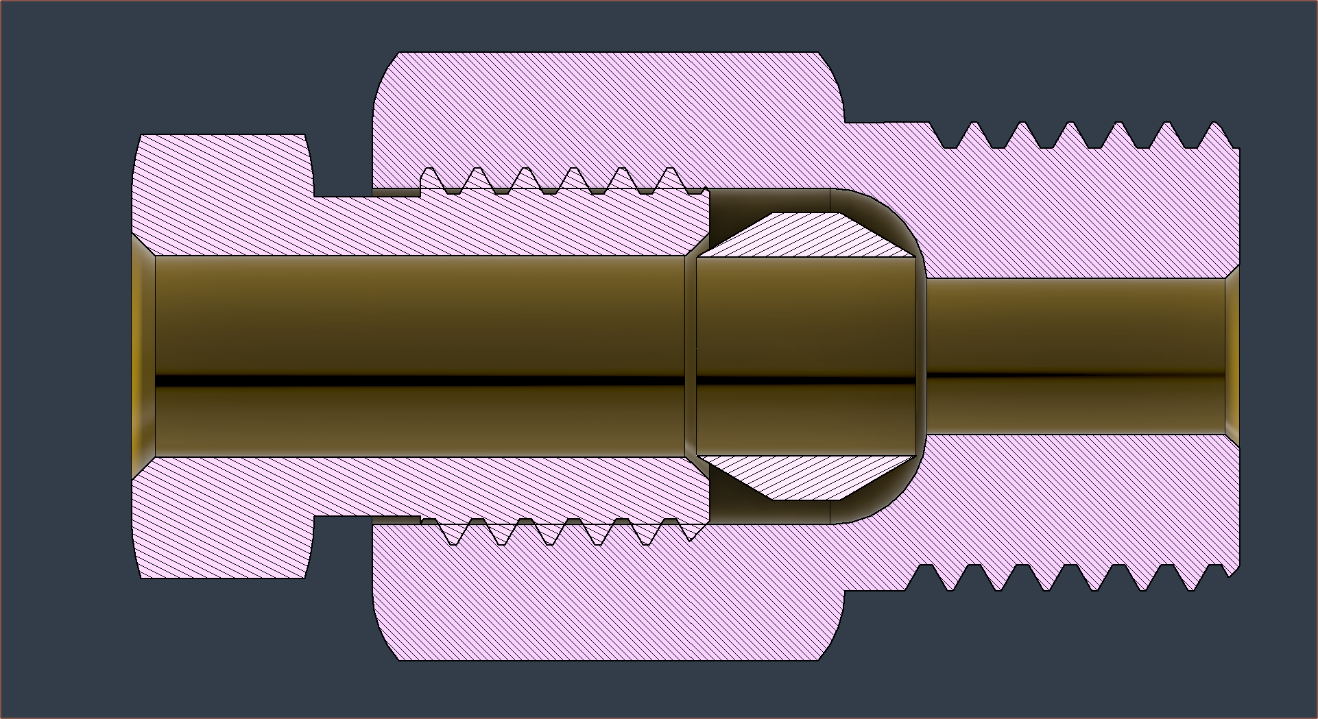
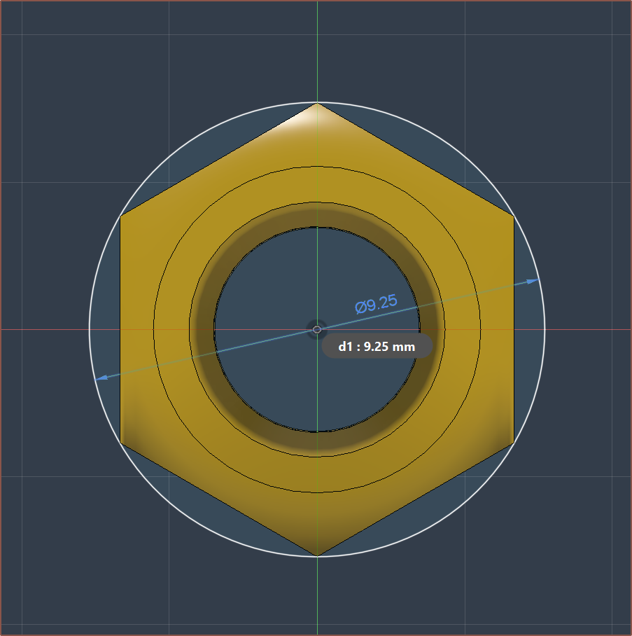
Looking at the internals, I think PCBWay could metal-3D print the internal geometry of the large threaded part, meaning that I only have to consider the space required by the small threaded part, which is only a diameter of 9.25mm or so:
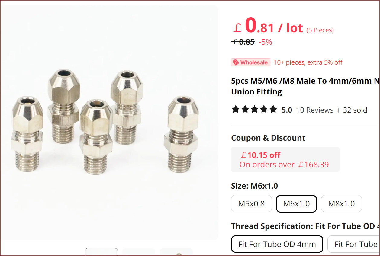
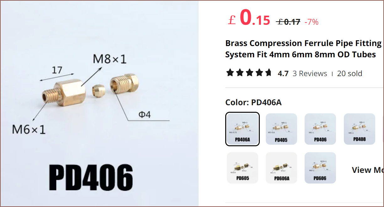
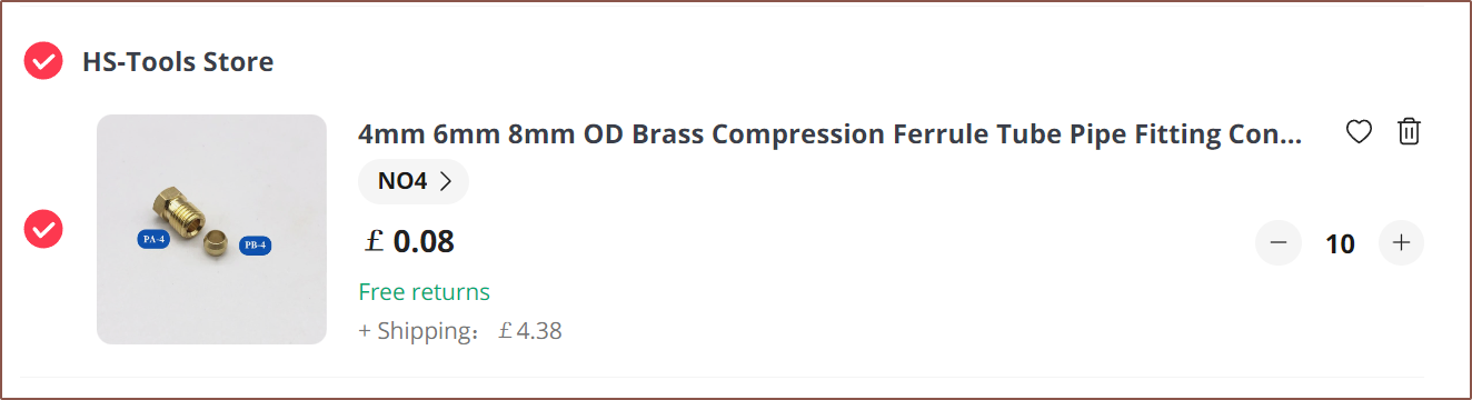
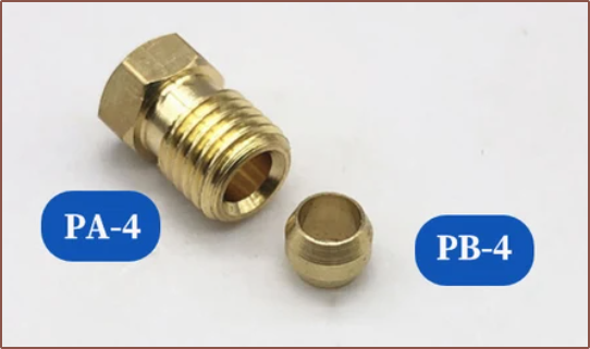
There's actually a few listings that are only the 2 parts I need (on the hotend side):
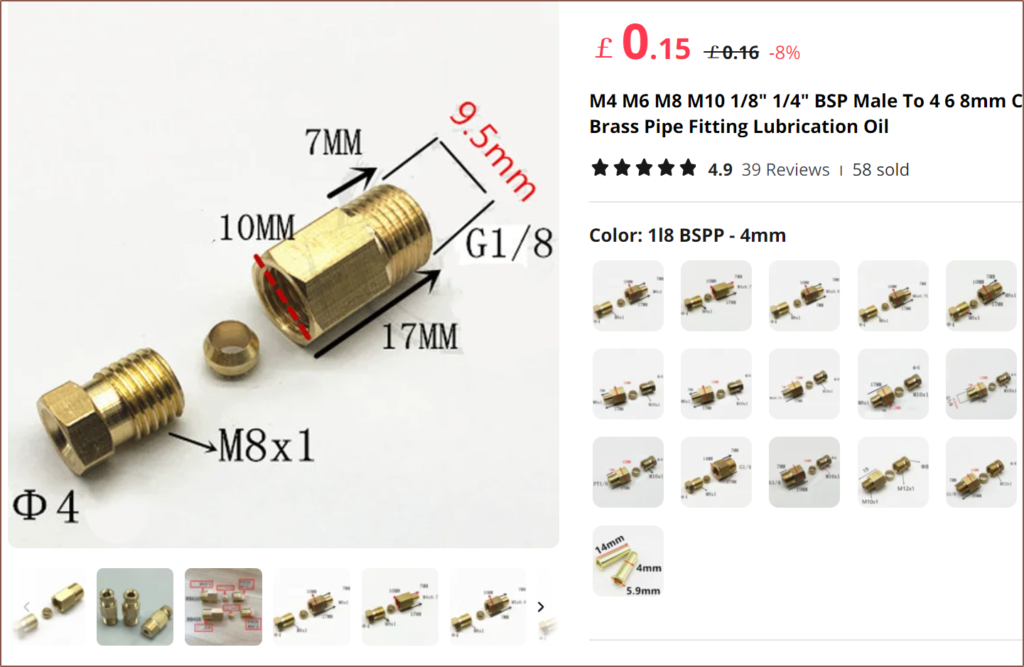
For the extruder side, I'm thinking of this:
I'm thinking of just getting 20pcs of these because cheaper shipping makes the overal order cheaper.
Discussions
Become a Hackaday.io Member
Create an account to leave a comment. Already have an account? Log In.