 kelvinA
You know how the CR600S got its name? Well it's simple. With a large-at-the-time build volume of 300*300mm and my craving for speed, a 0.4mm nozzle installed in my CR-10 just wasn't enough, so I got a 0.8mm one. Whilst dramatically speeding up print times, the cooling requirements and at-the-time minimum printable wall thickness of 1.6mm brought it's own set of pain-points. Lastly, multiple months after trying to tune in a 0.8mm nozzle, I tried a 0.6mm and it was the Goldilocks zone. At that point, so many changes had happened to the printer that it didn't feel right still calling it a CR-10, so it became the CR 600 (micrometer) Series.
Anyway, I was wondering if the same could apply to the coaxial hotend. 4-in-1-out isn't quite there for the requirements of full-colour printing, lacking inputs for black or soluable support material, but 8-in-1-out needs a lot of extra plumbing. 6 could once again be the ideal balance. However, I'm starting to understand why Me In The Past gave up:
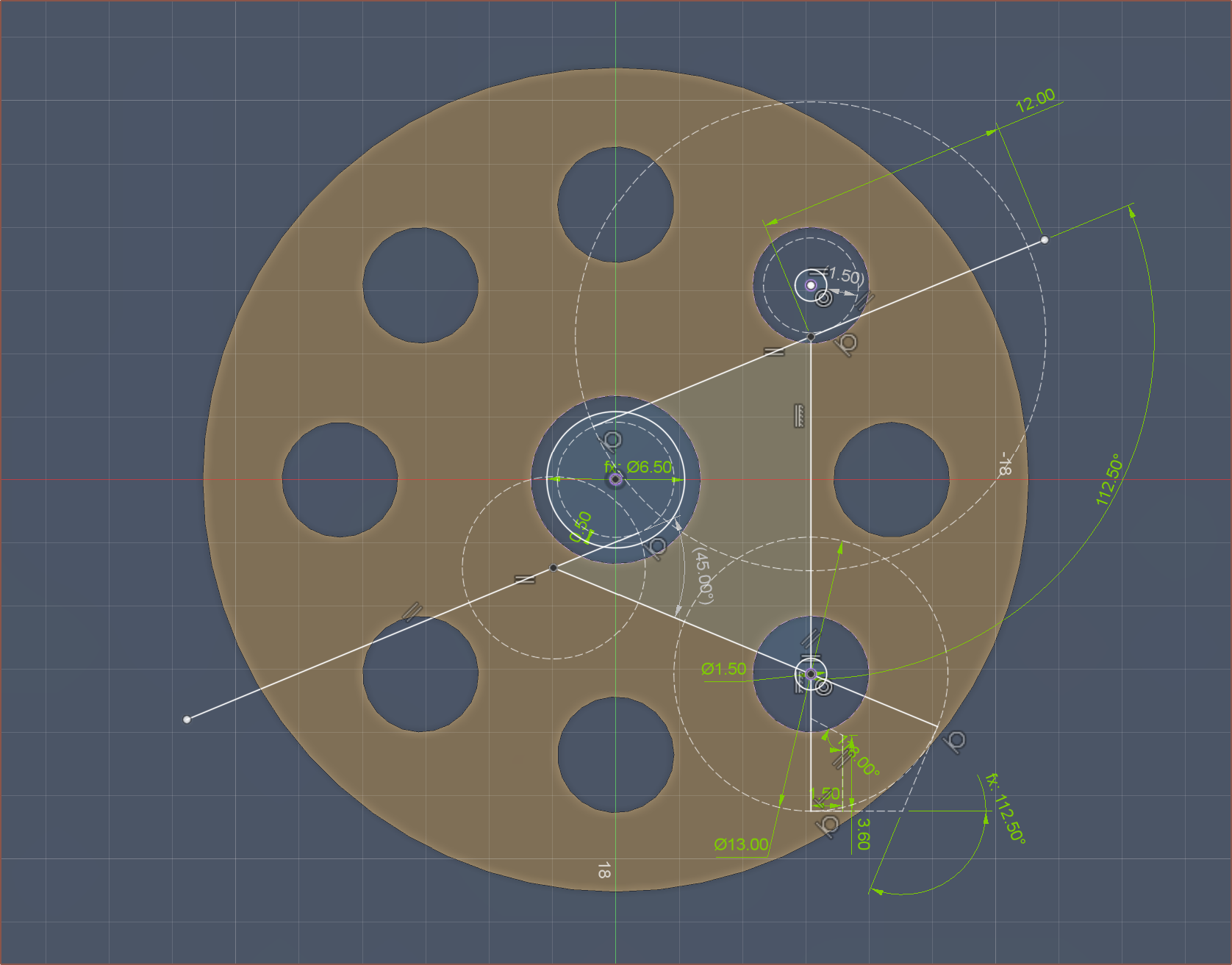
You see that circle with "1.50" in it? Yeah uh 1.5mm is also the radius of the hole plugs. In other words, there is 0mm of material between the vertical shafts and the ball-plug holes with an angle divisible by an angle derived from the following equation:
180 / ( Inputs + 2 )
Now there's probably a solution if you disregard this and tell the CNC lathe to just mill all the specific angles, but that increases complexity compared to the 8-in-1-out that just needs 10 angles. Any unused paths can just be sealed away with an M6 grub screw. Another solution may be to remove the centrifugal design.
Speaking about that 8-in-1-out, I just found out that the minimum distance between inputs was only around 8mm or so, and any PTFE coupler I'd use would need at least 10mm, so I've spaced them out more. The diameter only increased by about 6mm (aka diameter = 46.3mm).
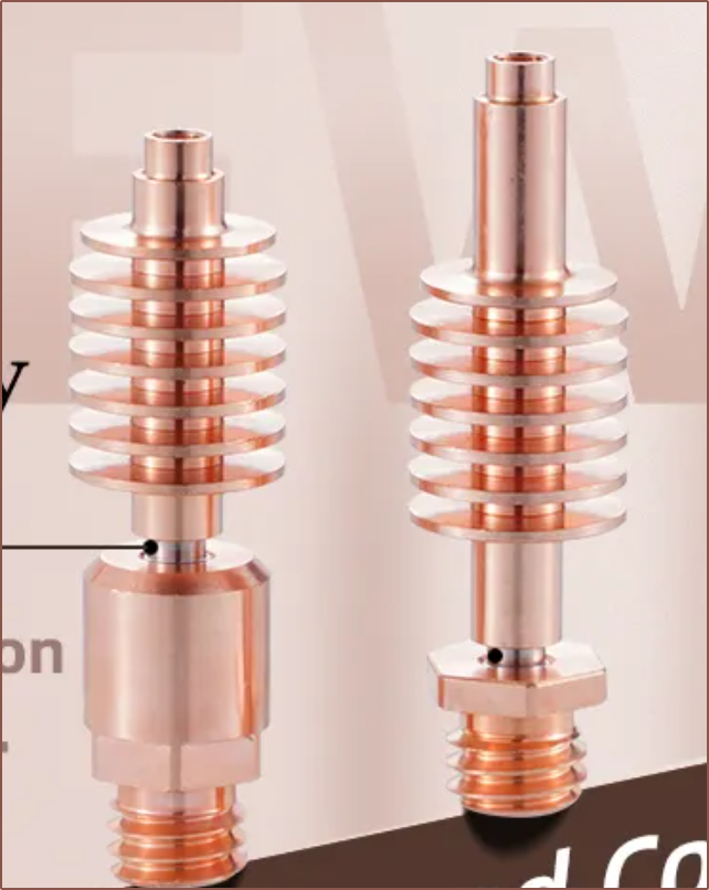
Also, I'm thinking of using the "high flow" version of the heatbreak-heatsinks so that the material can be pre-melted before going into 1.5mm diameter shafts, further reducing the amount of molten material actually inside the coaxial block. It's also reduced so that the minimum wall distance can be increased.
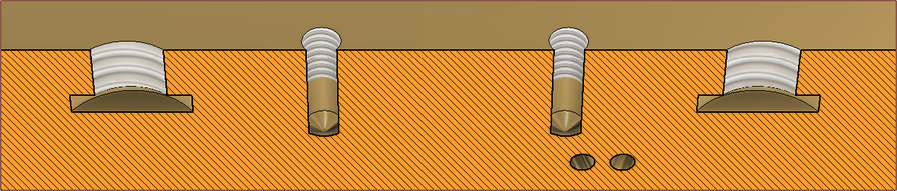
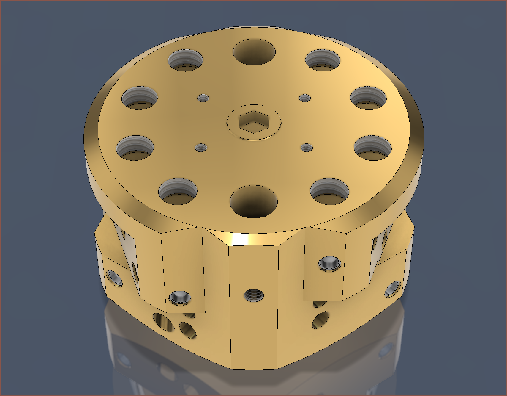
I've also changed the M6 undercut so that it uses the same tool as for the internal grooves. All groove depths have been reduced to 0.75mm.
Minimum wall distance is 1mm:
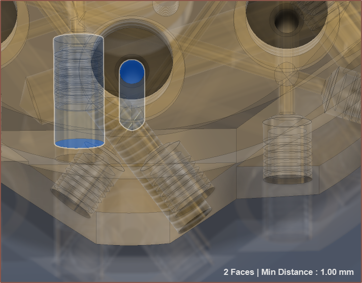
This also applies to the internal grooves, reducing the length by 1.4mm to 29.0mm. This also means that the insert is 23.5mm, likely meaning that an M8x25mm grub could be used as the stock material. I also got rid of the flat face for the thermistor (see bottom left of image below).
Another thing to mention is that a 6mm bore is the minimum diameter geometrically viable, meaning that an M7 thread is the minimum that can be tapped. Thus, without having to get custom nozzles, either the dual-heater-zone strategy or a custom thread-reducer part is required.
Discussions
Become a Hackaday.io Member
Create an account to leave a comment. Already have an account? Log In.