 kelvinA
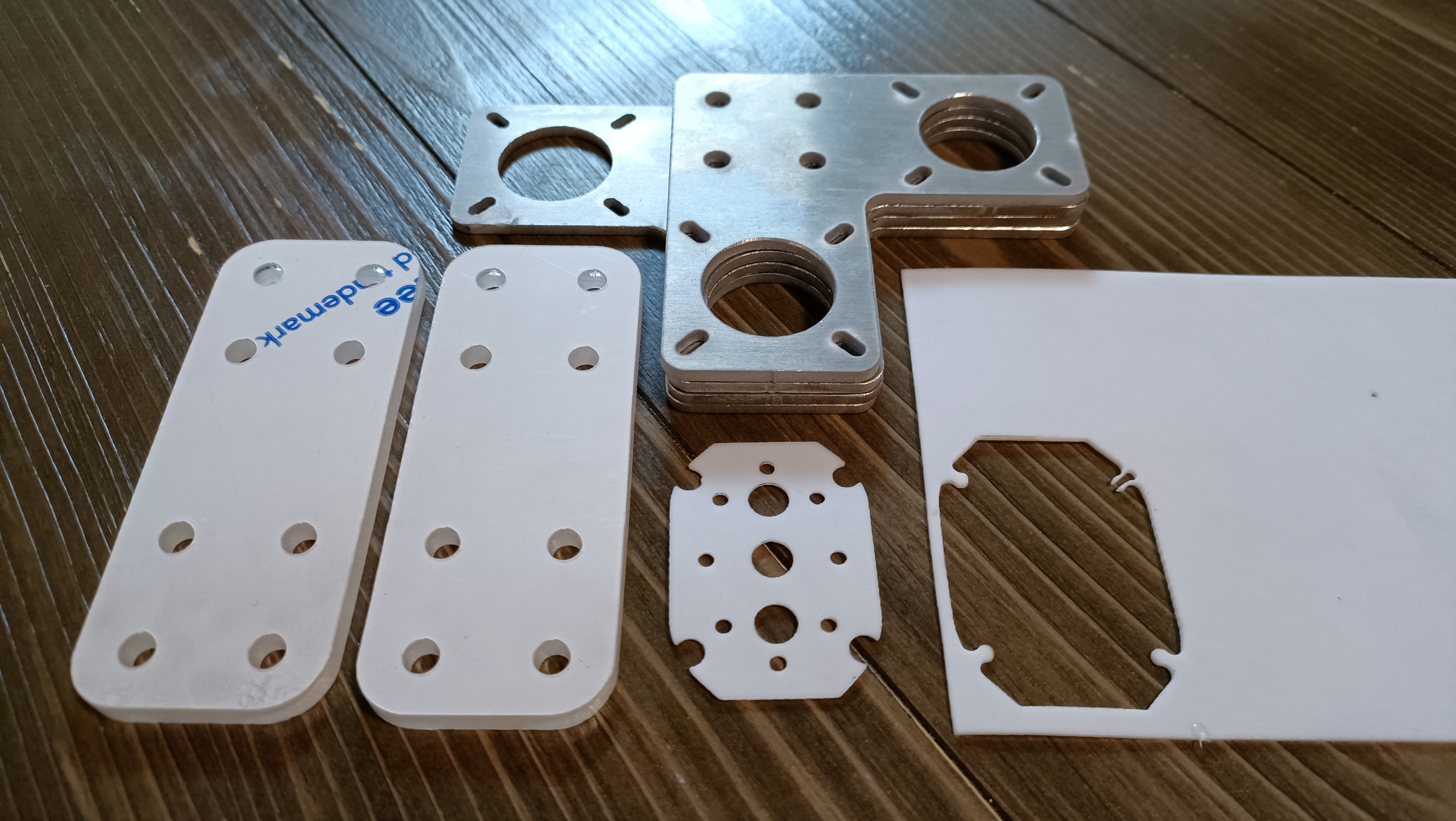 The university happens to have a wide variety of manufacturing facilities.
Laser cutting the motor spacers
The first thing I tried to do was laser cutting. The plan was to ask for some 6mm acrylic for the motor spacers and then laser cut the 1mm PTFE that came in the mail a few days back for £2 delivered. The original idea was for 5mm acrylic but I thought that I'd err on the side of caution.
The PTFE seller exceeded expectations; on the listing it says "at least 80 x 80mm" and I got a 100 x 150mm piece which is 50% more PTFE than other listings that cost 100% as much. However, the laser cutter technician said that he'd need to ask around to see if PTFE could even be laser cut.
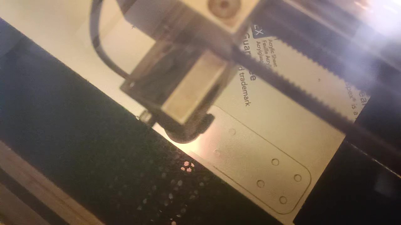
The acrylic was fine though, so we just progressed to focus on that.
We hit a hurdle almost immediately as some software called "ApS Ethos" wasn't showing the .DXF exported from Fusion, even when moving the files to negative co-ordinates. The solution was running it though Solidwords 2023 that the uni happens to have installed on the engineering PCs. ("Awfully recent, if you ask me" I thought, since Solidworks does a yearly edition (that costs money) instead of these sweet 6-week free updates on the Fusion side of life.) It turned a 4KB into a seemingly identical 22KB file, but this showed up in the Ethos software.
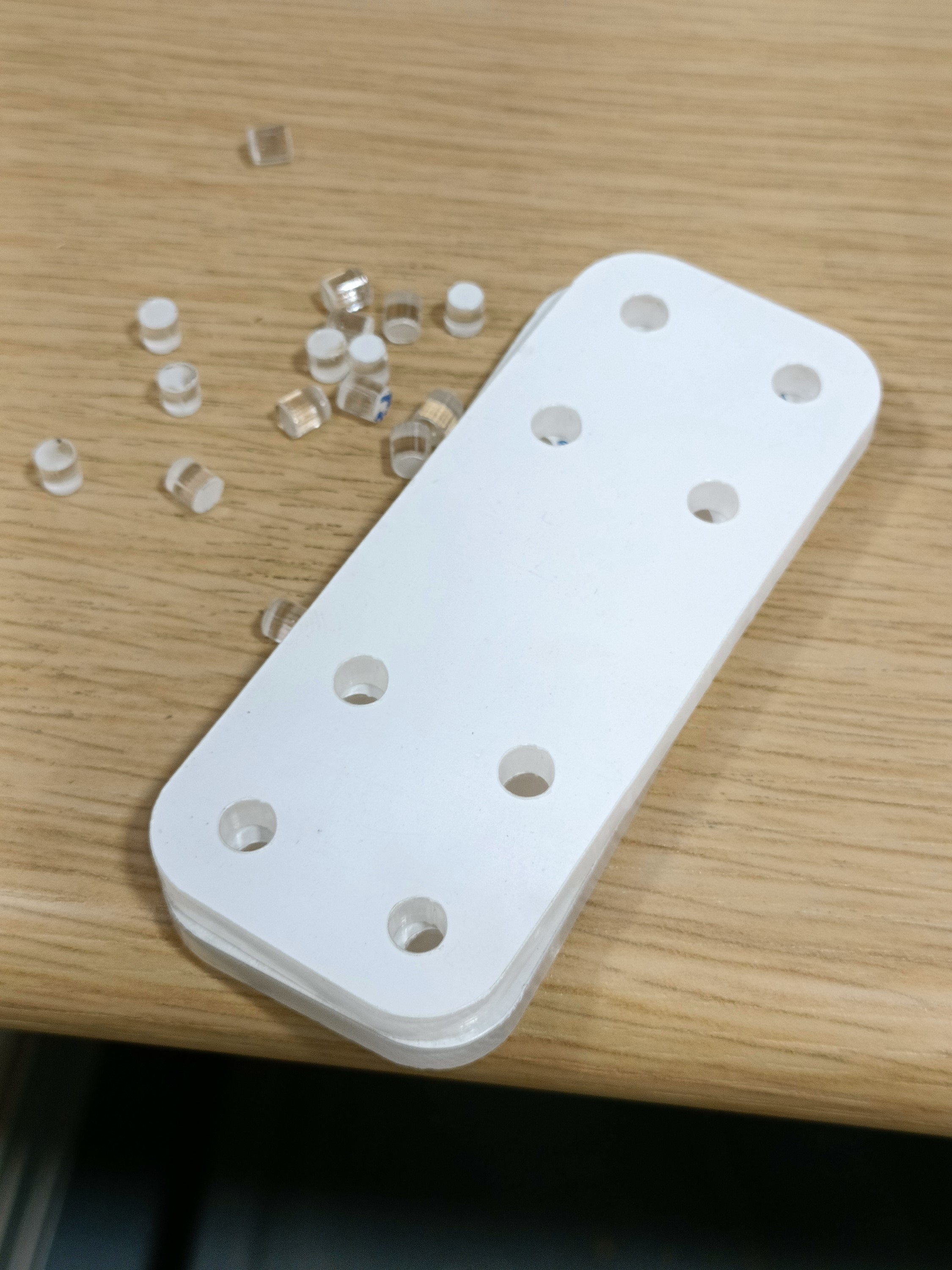
Things moved really fast after that. There was only 5mm acrylic on hand so that's what we chose. It's actually transparent so it seems that, unlike the dark-mode theme that my 4-in-1-out extruder setup was, everything is going to be a silver / transparent light-mode theme.
The holes were increased to 5.1mm ahead of time to coincide with the metal plates, and the result were holes between 5.08 and 5.15mm so I think that +0.1mm is fine for clearance if I need another part in the future.
Abrasive cutting the other 2 parts
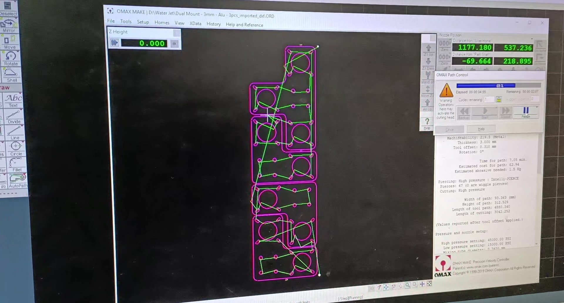
I mainly went to the workshop to ask about the metal plates, as the university happens to have a massive "1530" water cutter, and only at the end did I mention about the gasket I was trying to get cut out. He asked how thick it was and figured that it was cutable.
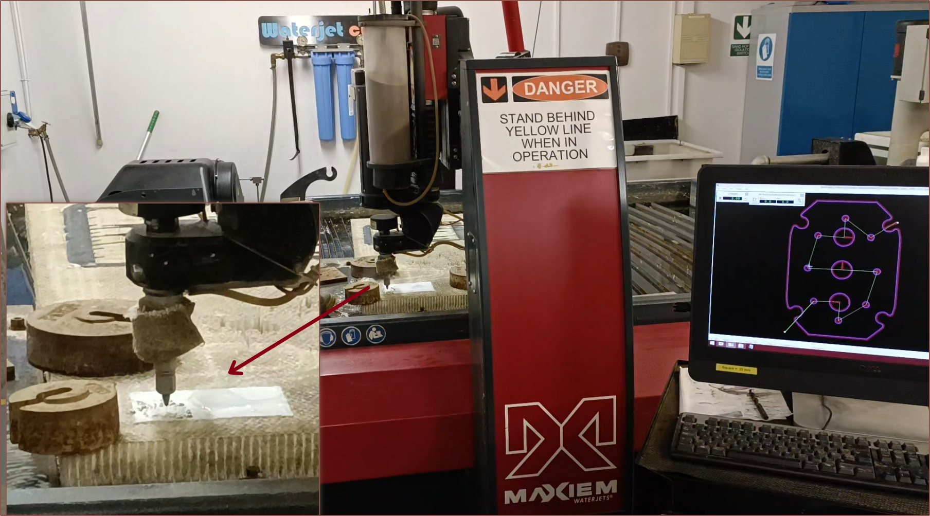
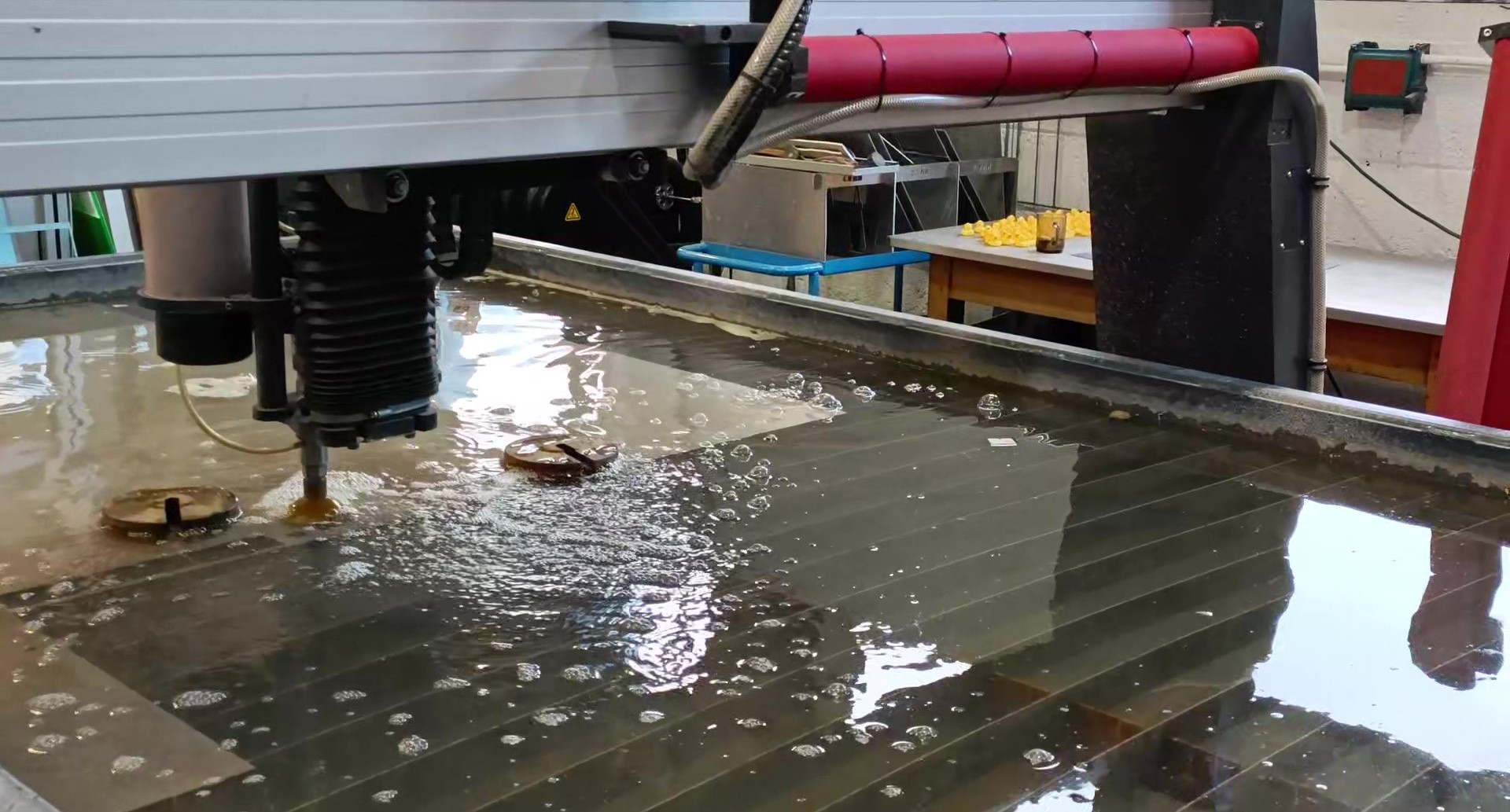
So, with the soft material cutter my university just happens to have...
Really! Hidden away in an inconspicuous corner, past some flat sheet metal stock (making it seem like an even more inconspicuous corner), was a very large machine about half the size of the water cutter which is made by the same company. It's like a water cutter without as much water, from what I could tell. It's also so much louder.
So I gave the PTFE to the first tech that I spoke to and he said that he's never handled an entire sheet of PTFE before and noted that it's got some stiffness to it. I agree; it's not something floppy like what silicone probably would've been. It's also nice to know that every day really is a new learning opportunity for the techs.
One of the techs hot-glued the edges of the PTFE to something that I assume is a sacrificial honeycomb. This is because PTFE doesn't stick to tape so the hot-glue acts as a part holder when it cools (at least that was my understanding of the situation). They've never cut PTFE so he set the material to nylon in the software. Oh and this software took the Fusion DXF just fine btw.
At the same time, the motor mounts were being cut
After that was done, I needed to file the tabs that were left behind, as well as debur the edges. One side is notably sharper than the other side.
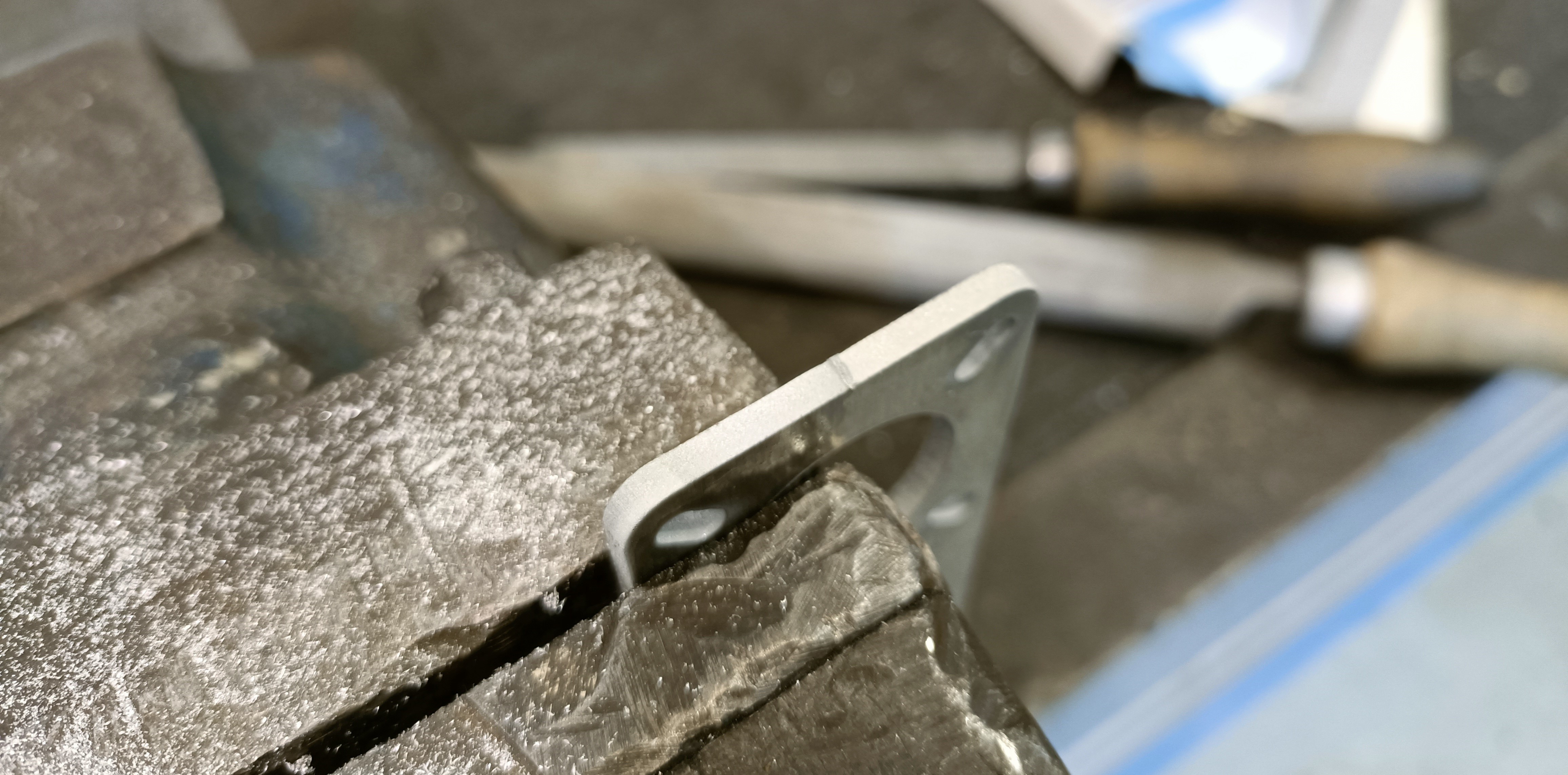
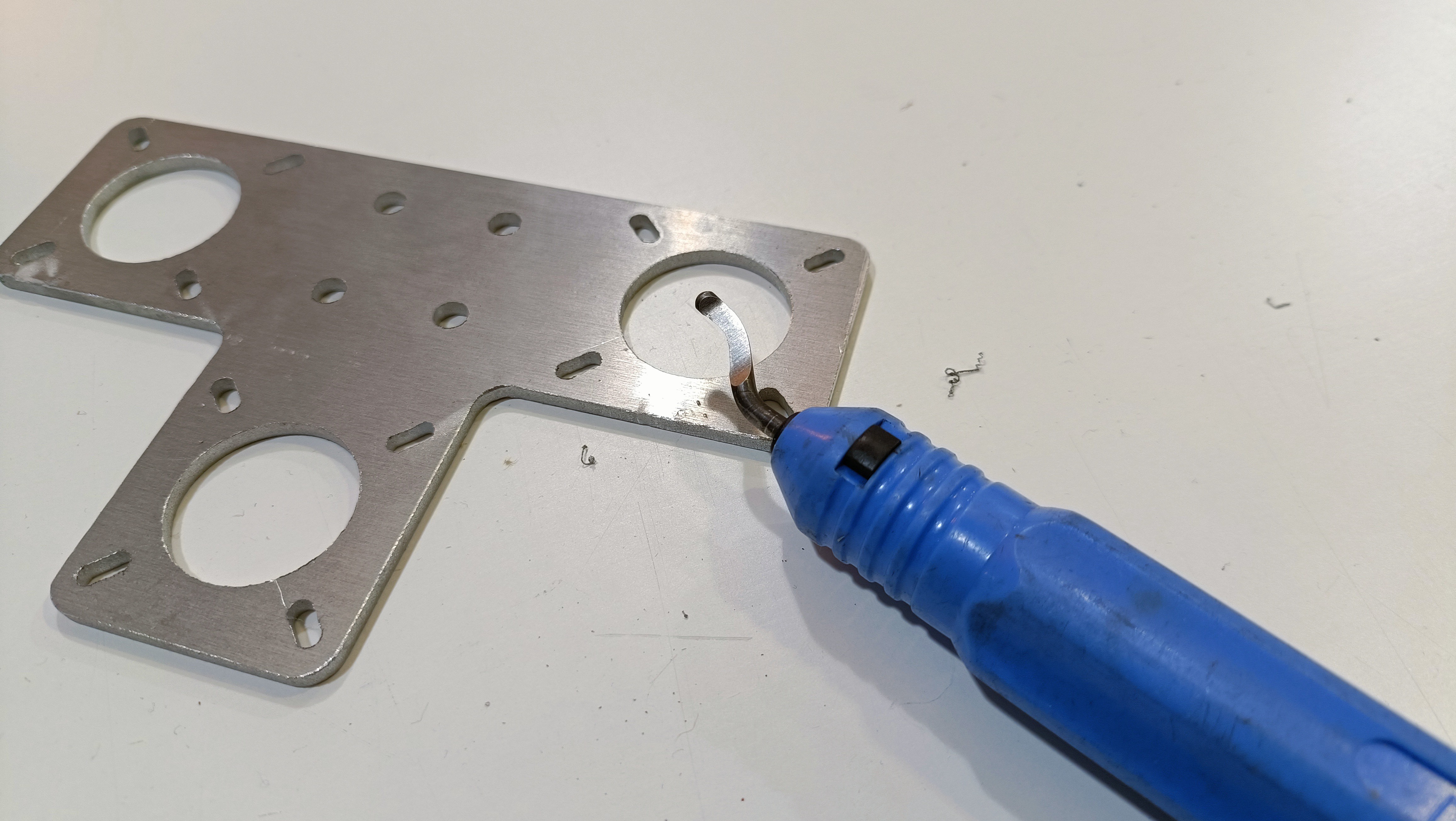
I used the large file to file away most of the tabs and then the small file for the rest of the tab and deburing the edges. This strategy wasn't ideal for the large inner holes, but the uni tech guy just happened to have a handy deburing tool:
Finally I just had to brush off the parts and wash off my hands. The university workshop happens to have some interesting soap with granules in it:
Dimensional tolerances
The small holes for the PTFE gasket were 2.75mm and the cartridge holes were over 7mm, which was larger than the 2.3mm and 6.7mm respectively I modelled. Theoretically, there shouldn't be any problem with this as long as everything holds up. It also gives me just a bit more misalignment tolerance. I'm just a bit 👀 when it comes to the 2 inputs closest to the heater cartridges because, like with the clamp plate, that is where material is thinnest.
The water cutter tolerances are closer to expected, if slightly undersized.
Other things to mention while I'm here
- The print order is "at 50%", which means that it's actually finished being programmed and is now printing.
- I'm going to get 2x70W heater cartridges because the Coaxial8or is double the volume of the test 4-in-1-out.
- I've switched the pins so that these heaters are run off the bed mosfet.
- I'm going with TMC2226's for all motors because, with XYZ on the BTT Motor Expansion, those axes now get their own dedicated DIAG pin (for sensorless homing) instead of having to share with endstops.
- Technically, I could just tweak the endstop positions on a normal board configuration
- I'm going to try this PTFE sock from FysetC to hopefully prevent material from sticking to the nozzle when testing
Discussions
Become a Hackaday.io Member
Create an account to leave a comment. Already have an account? Log In.