 kelvinA
Here's a progress update of what's happened in the past 2 days.
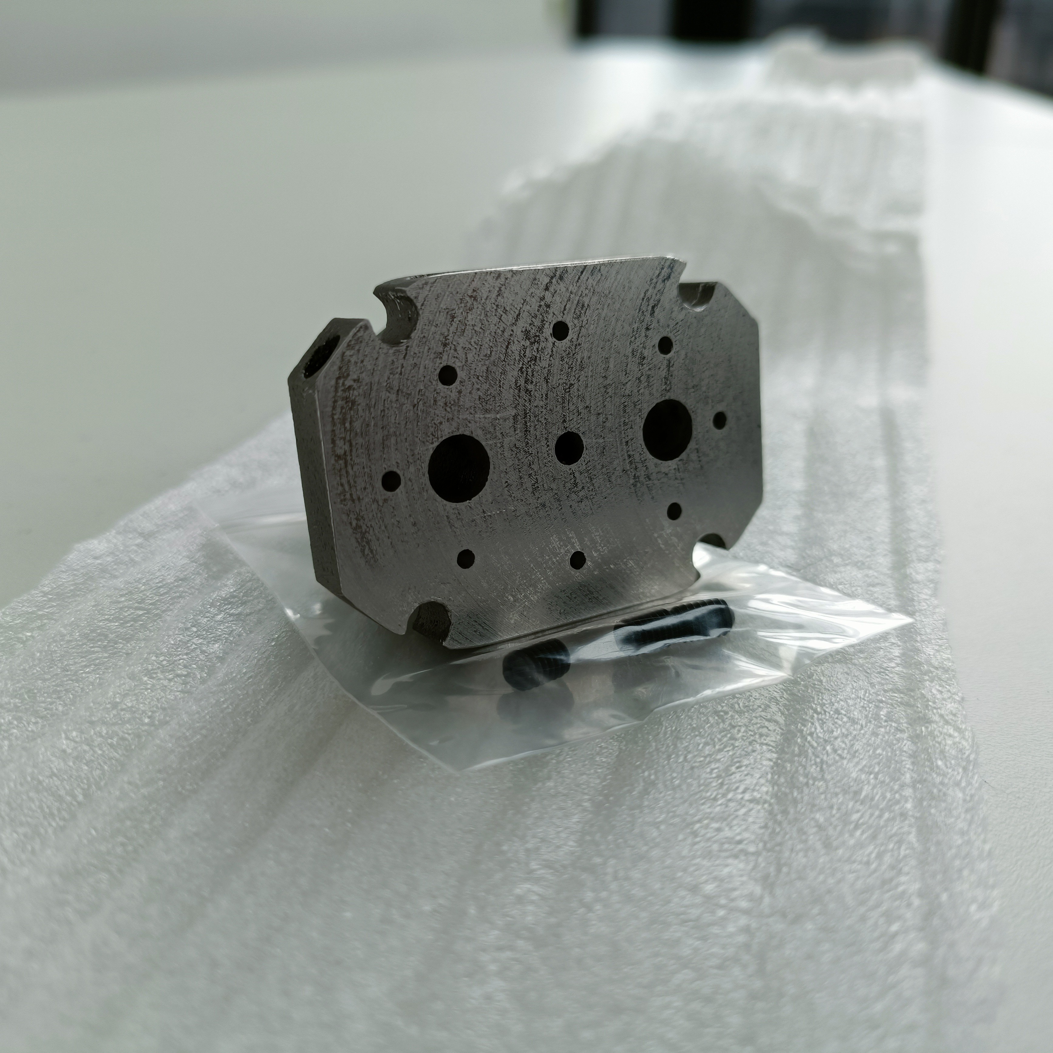
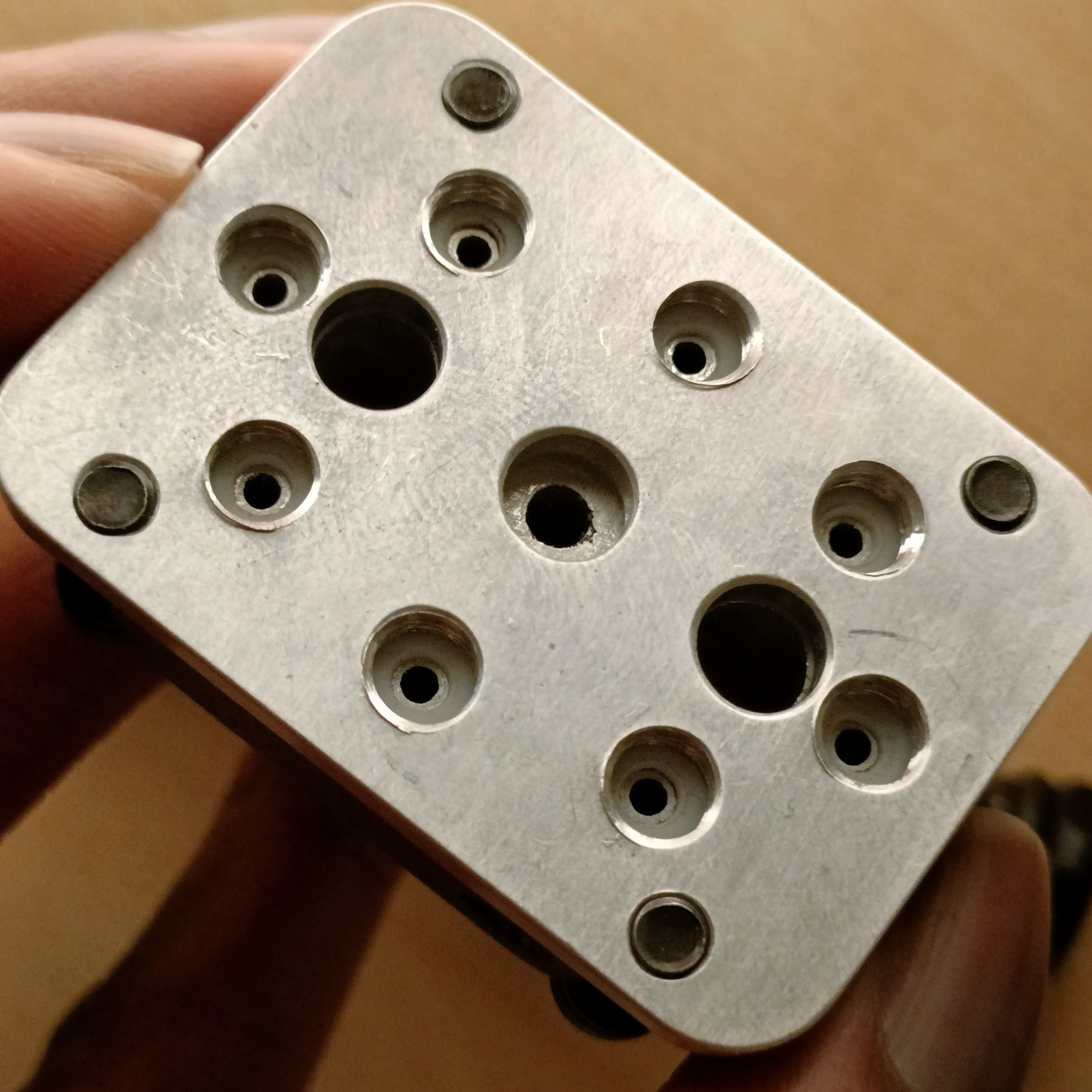
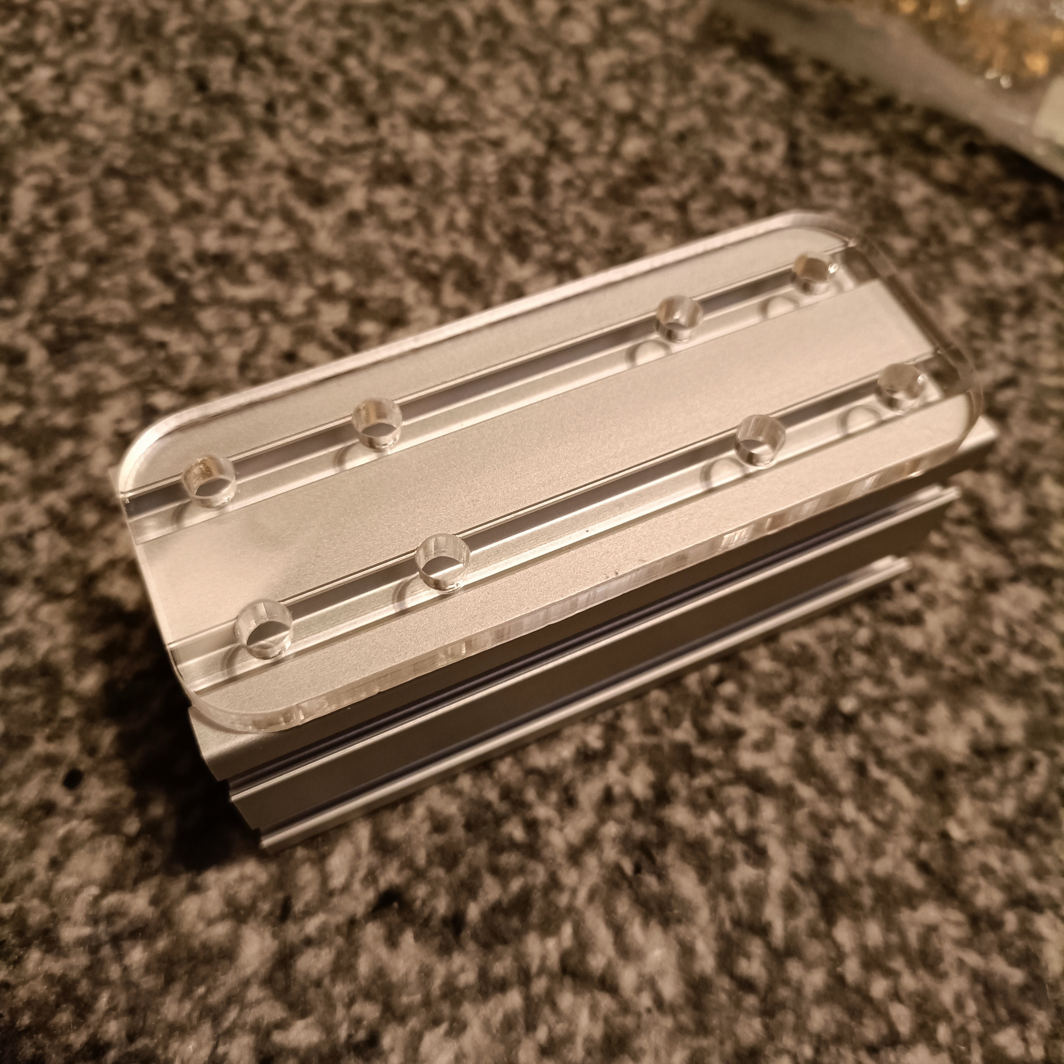
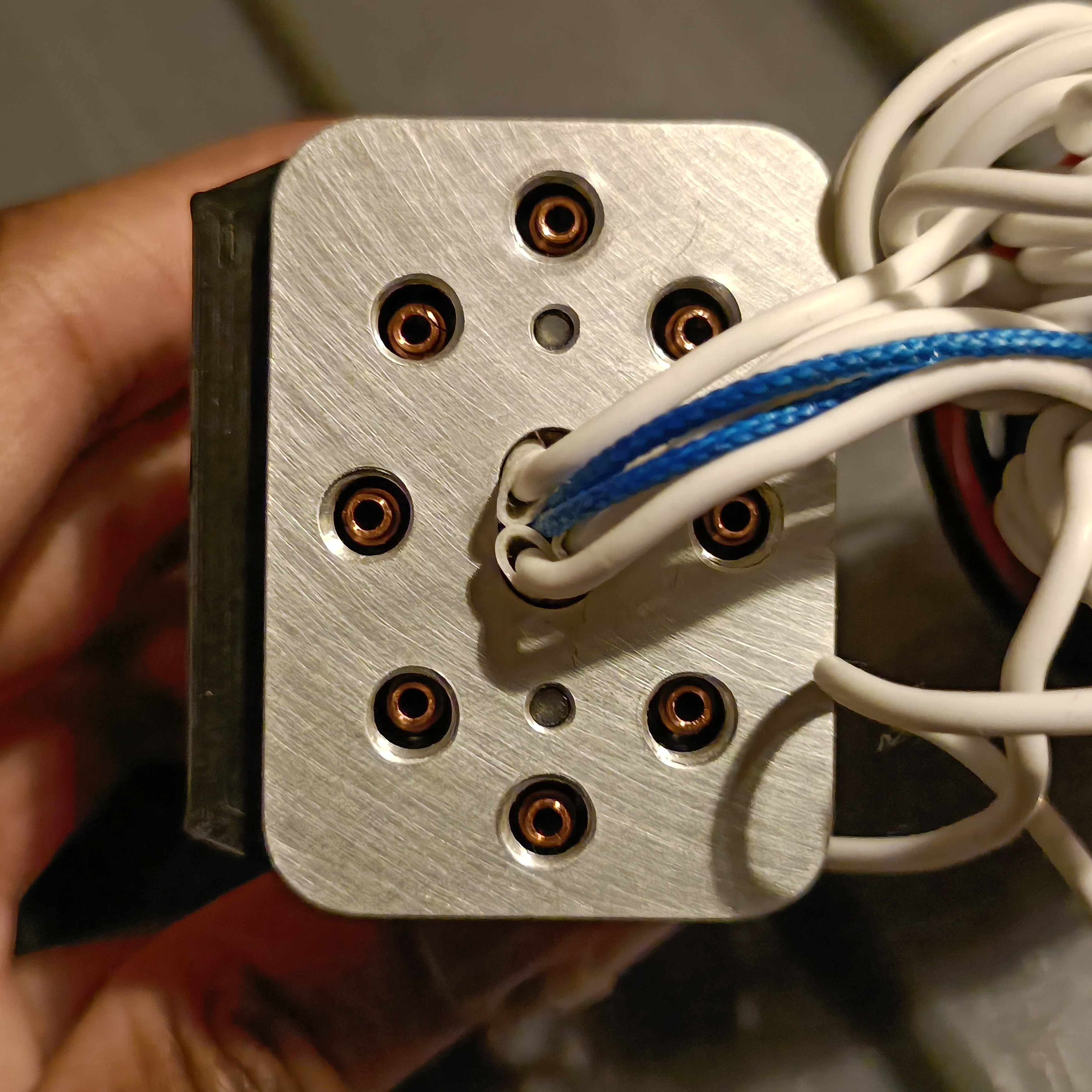
Face flattened and holes tapped
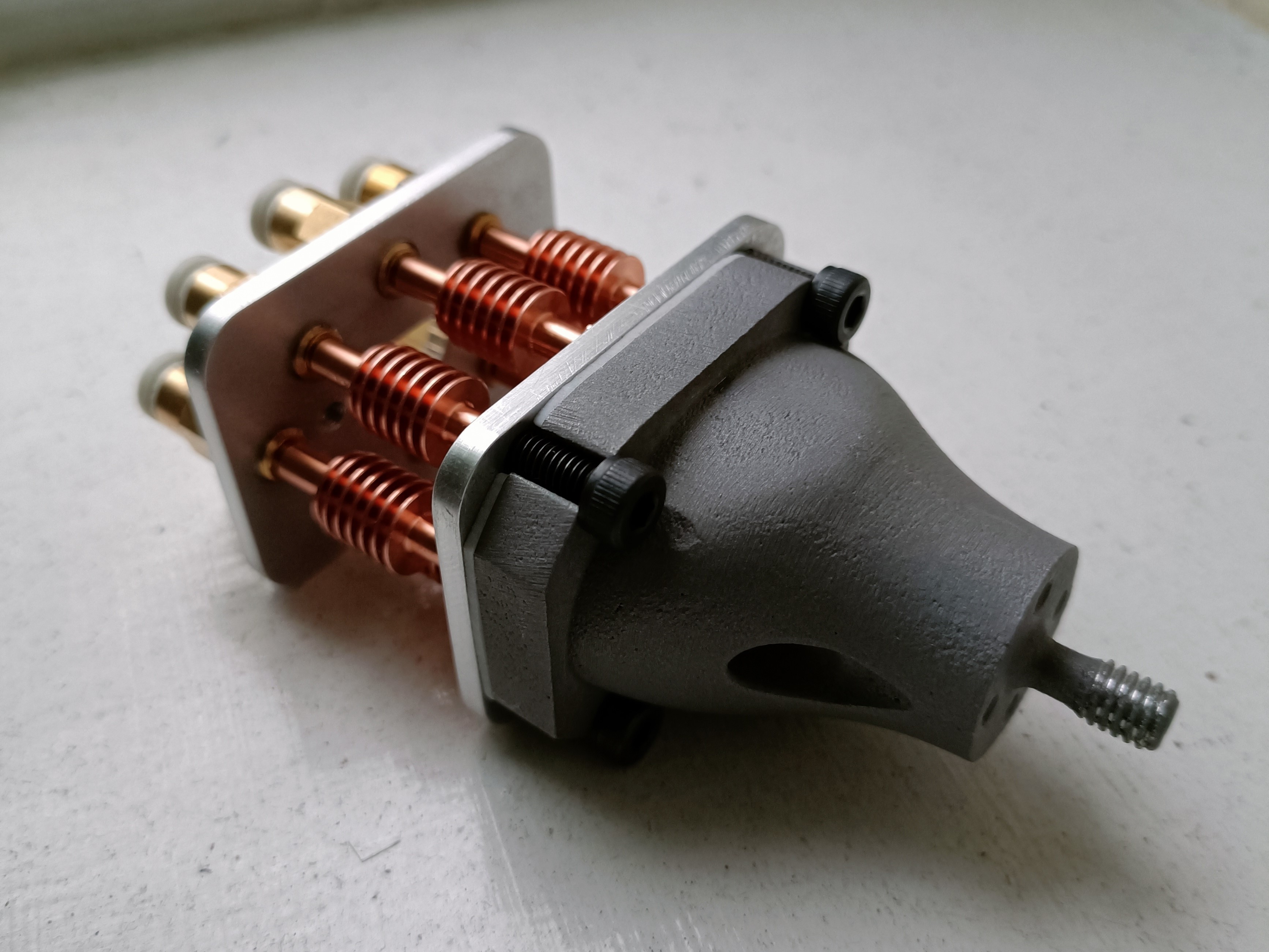
I also got some M4x6 grubs and M4x12 and M5x12 bolts for the coaxial heatblock and motor mounts. I chose M5x12 for the latter as they only had 5x M4x6 in stock and much more M5s, and I conveniently designed the motor hardware to accept M5s.
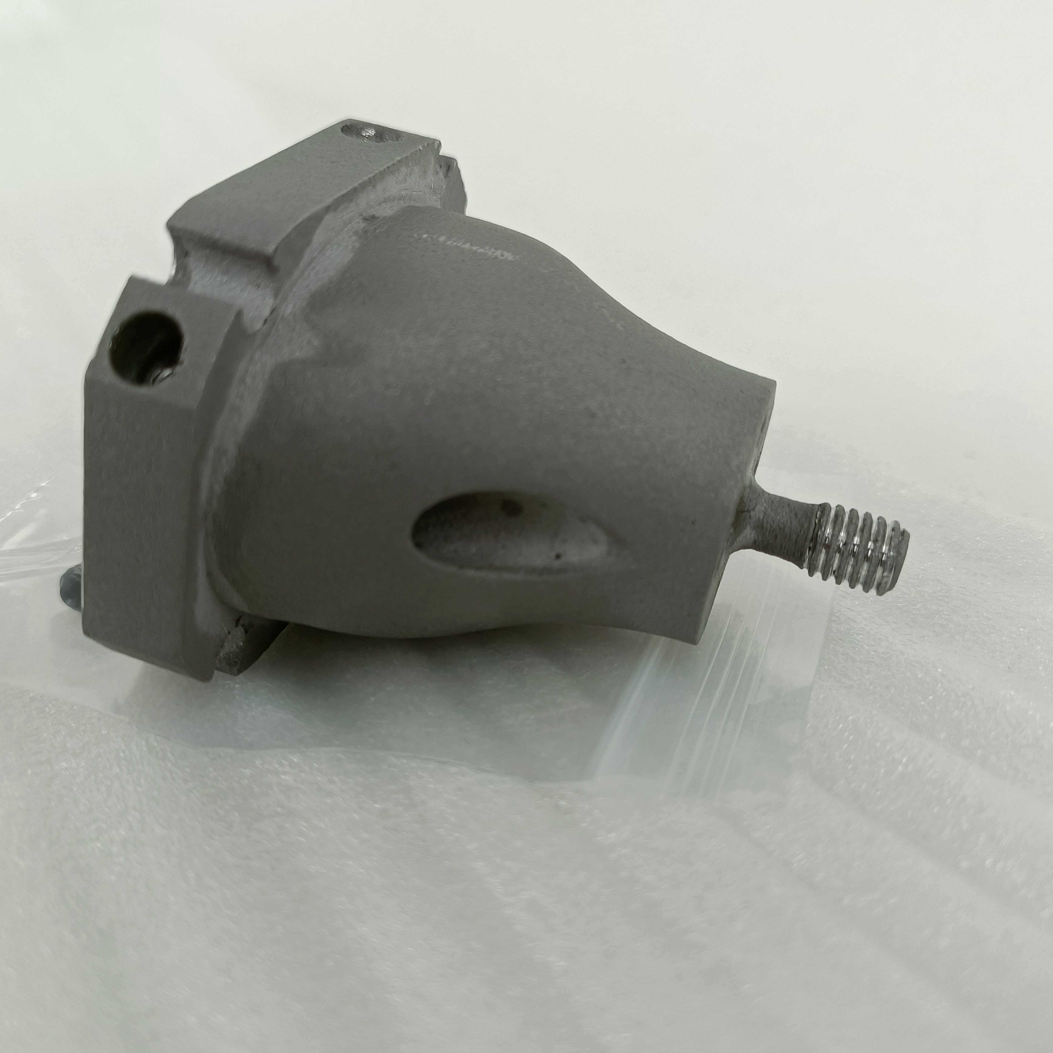
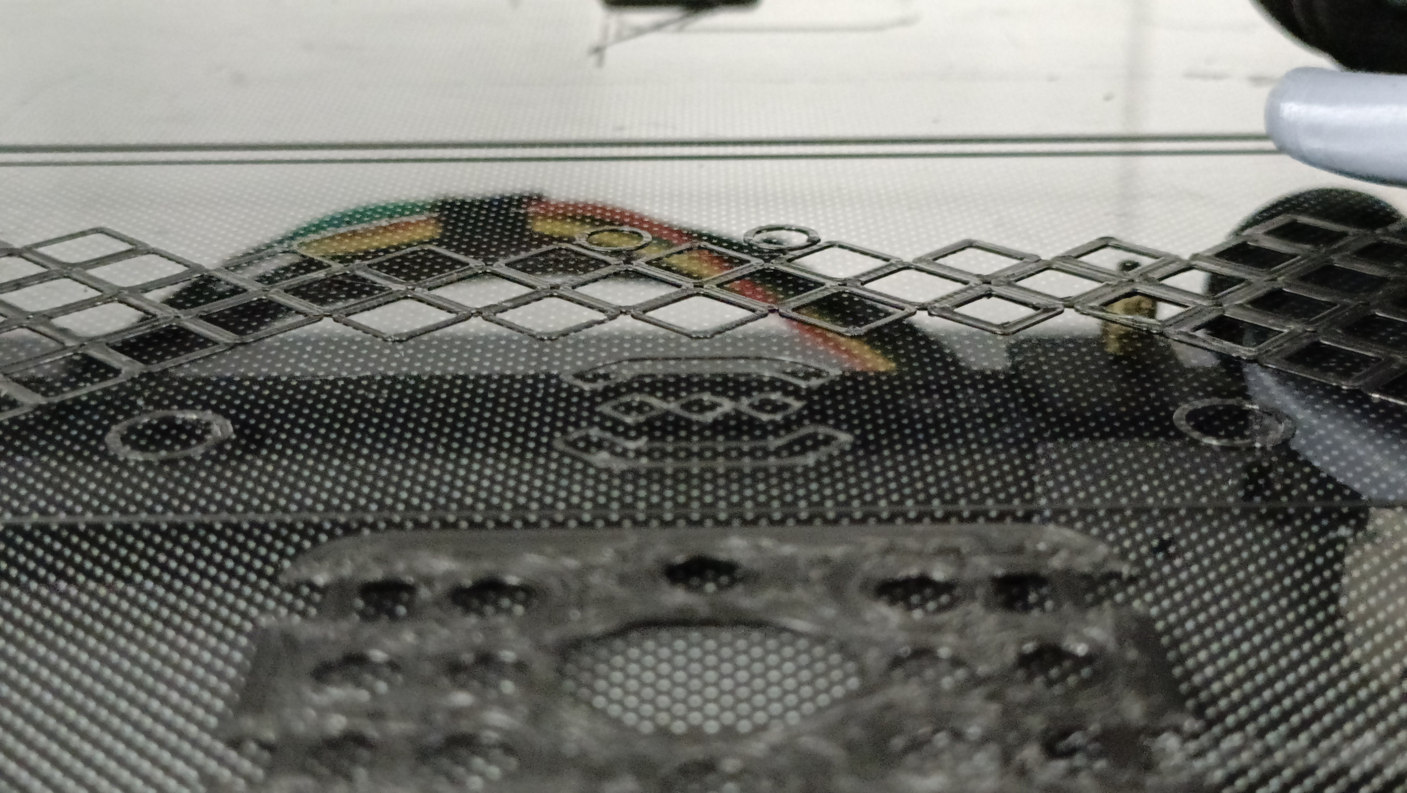
I also looked at the gasket again and there were light arc indentations, suggesting that the PTFE is still flexible enough to provide sealing.
Motors installed
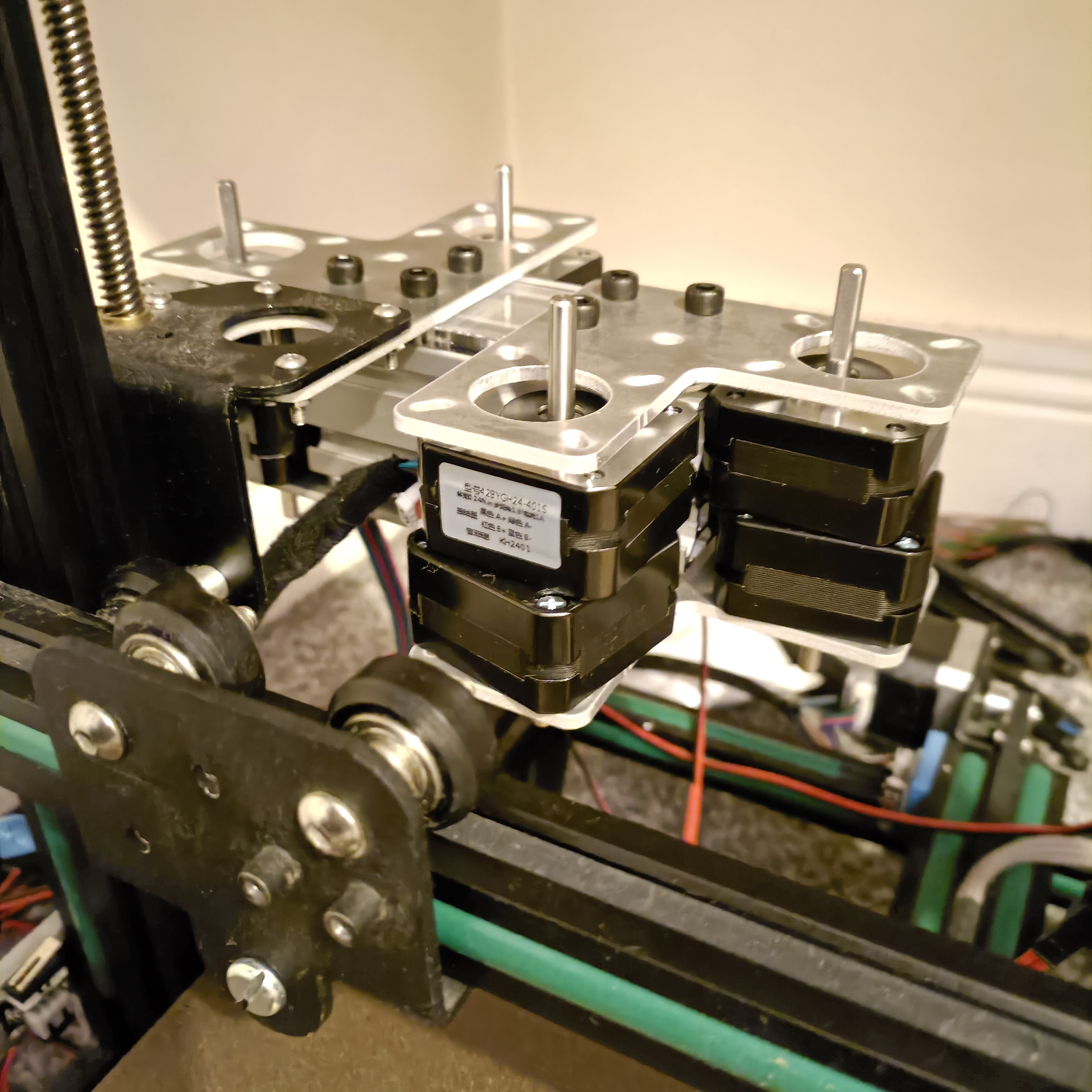
As it turns out, the cables that came with the motors are actually doubled up. It's an 8-wire ribbon cable that terminates to 2 motors on either end. I was trying to get some convoluted method so that i could identify which cable is what, but then I remembered that I bought some numbered cable markers and just used 2, 4, 6 and 8 on the motor that has the left termination on the Oct Pro (so Extruder 8 would be the last extruder). It does seem that the 1m cables will reach the expected location of the Octopus Pro
Then I tried Tesa fabric tape for the first time and it does look a lot better and more professional than multicoloured ribbon wire.
Also notice that I was able to find a thin-cap M5x25 bolt and I was able to use a regular M5 nut on the X carriage.
Right now I'm just waiting on bolts and wires to come in so that I can put the DDEs on.
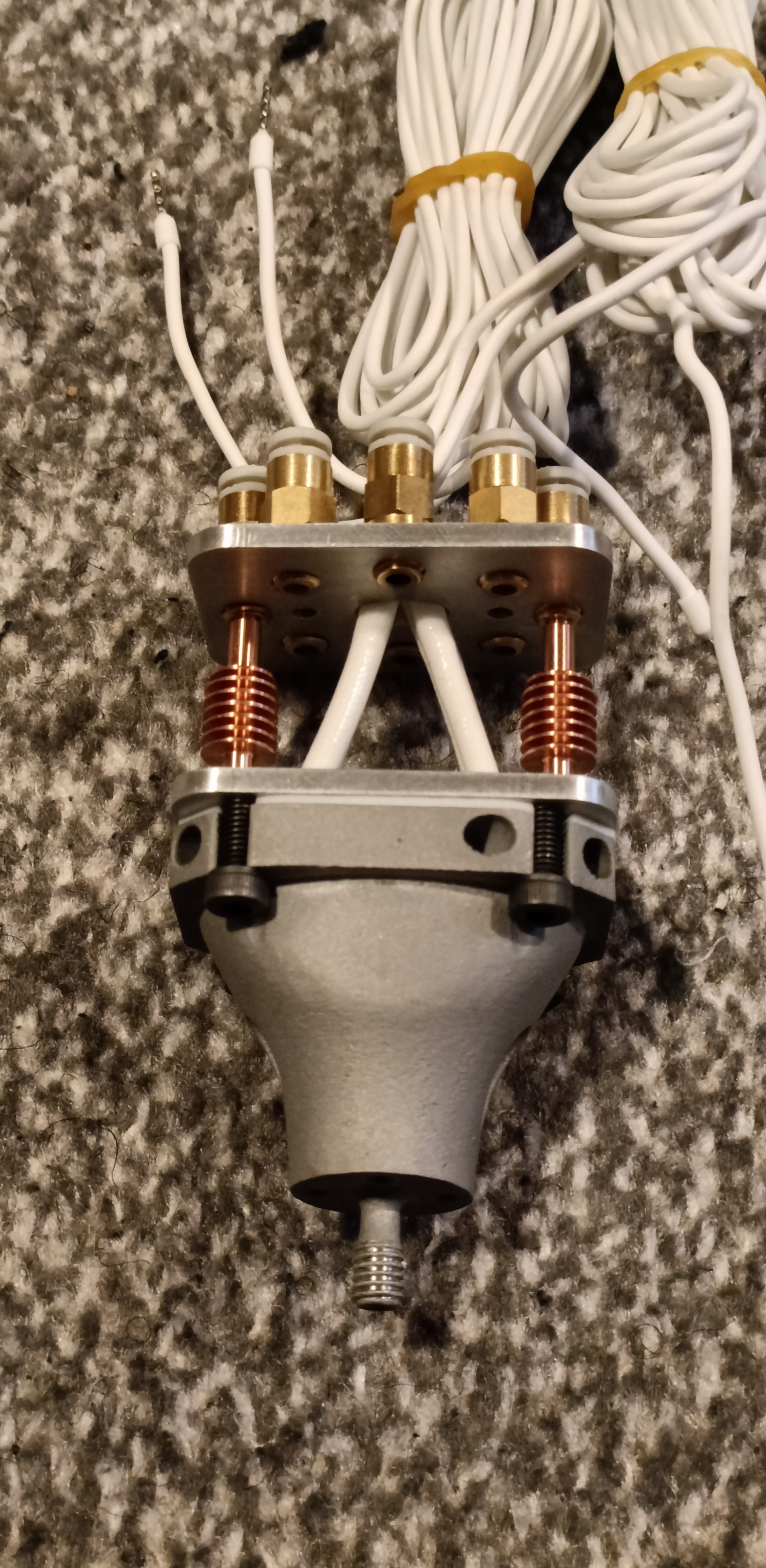
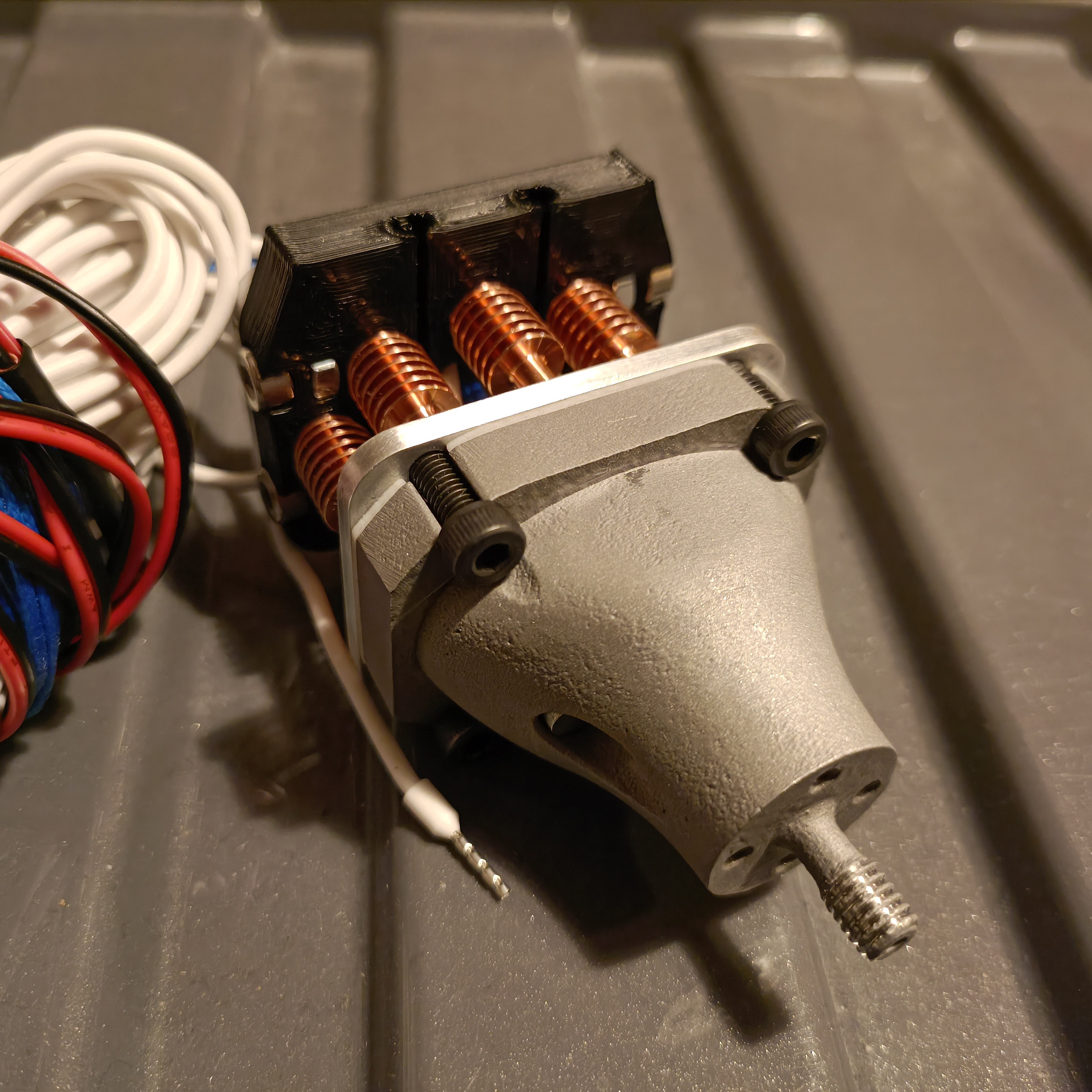
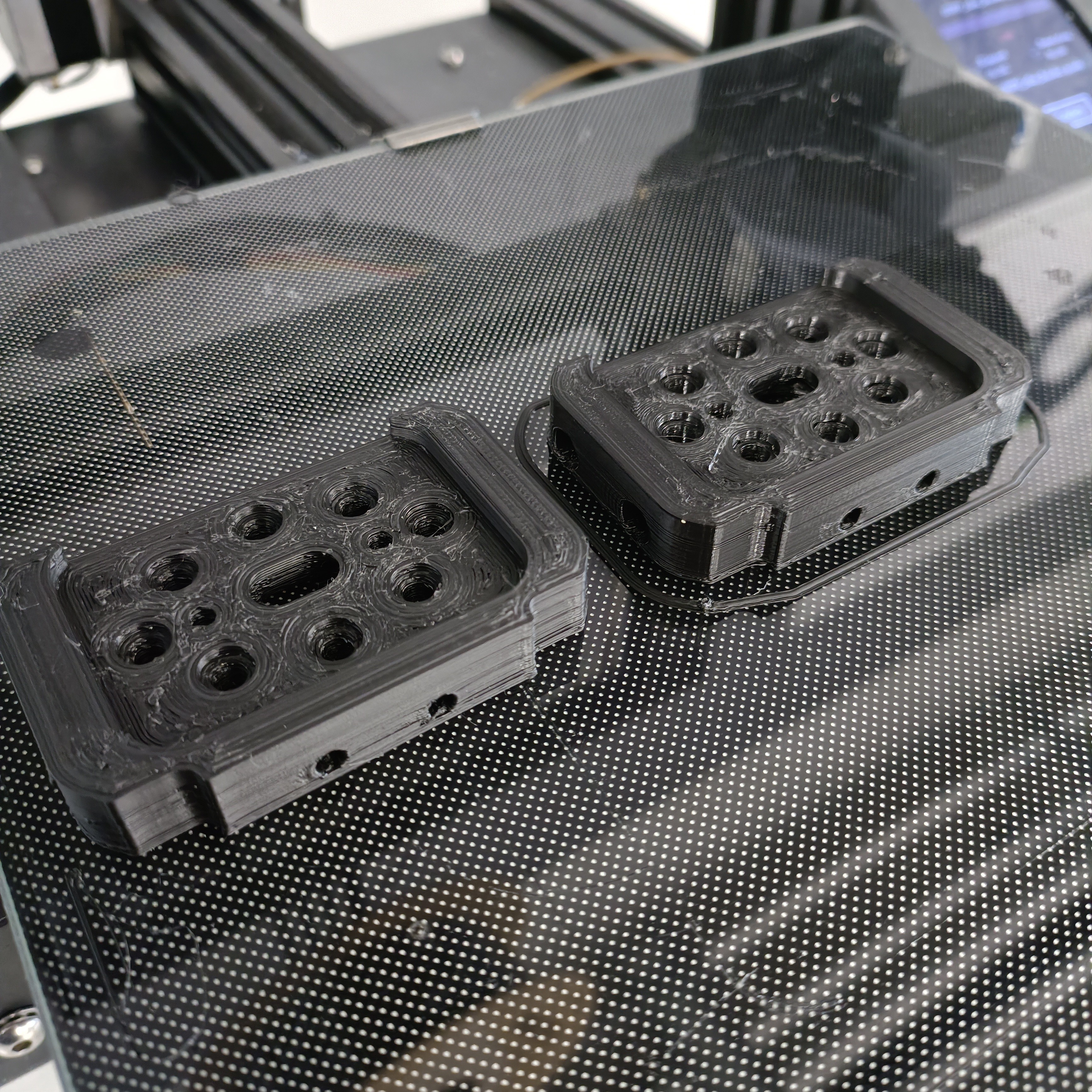
Hotend holder and cover printed
[13 Mar: 05:00] I've put the hotend mostly together, but understandable misalignments mean that I'm not quite able to align and fit the 8 PTFE couplers:
[13 Mar: 17:00] Lots more printer tuning and for an extra 7 mins of print time, the print came out much better:
It still didn't work though, but I was able to get the heatsinks to align when the holder was not installed, allowing filament to slide through a bowden tube without it catching hard on any surfaces. Thus, it does seem like it's still a hotend holder issue.
Discussions
Become a Hackaday.io Member
Create an account to leave a comment. Already have an account? Log In.