 Zdenek Hurak
Introduction and motivation
A thorough description of the platform, including some experimental results, can be found in our conference paper.
The project is still in development phase. We make a lot of changes, still we want to let you know about our work and give a snippet of it. If you are interested please do not hessitate to ask a question.
We publish all our work on our facaulty GitLab https://gitlab.fel.cvut.cz/SlotcarPlatooning
The project is divided in several parts and each part has its own git repository. These repositories then are added as submodules to slotcar.git for connecting versions.
Description of each repository
- slotcar-fs.git Slotcar Filesystem, cover filesystem for RPi CM (slotcar), and RPi (Wi-Fi AP). Eclipse project
- slotcar-fw.git Firmware for STM32F401. Eclipse project
- slotcar-sw.git Java SW for slocar APP and GUI. Eclipse project
- slotcar-ctrls.git Java controllers . Eclipse project
- slotcar-hw.git PCB designed in EAGLE
- slotcar-doc.git Documentation and papers
fs, fw, sw, ctrls are developed in Eclipse and project settings are included in these repositories. Therefore we would recommend you the same.
For working with java you need to have Maven, Git (optional) and CDT plugins. Additionaly we are using ANT scripts and SCP, therefore you need to add JSCH. Download it and add it to Eclipse
Window -> Preferences -> Ant -> Runtime -> Classpath -> Ant Home Entries -> Add External JARs...
For working with STM you need to have cross compiler and plugin, more information here.
You can easily add the projects into Eclipse by
File -> Import -> General -> Existing Projects into Workspace
Hardware
In this chapter we describe hardware solution and electronics.
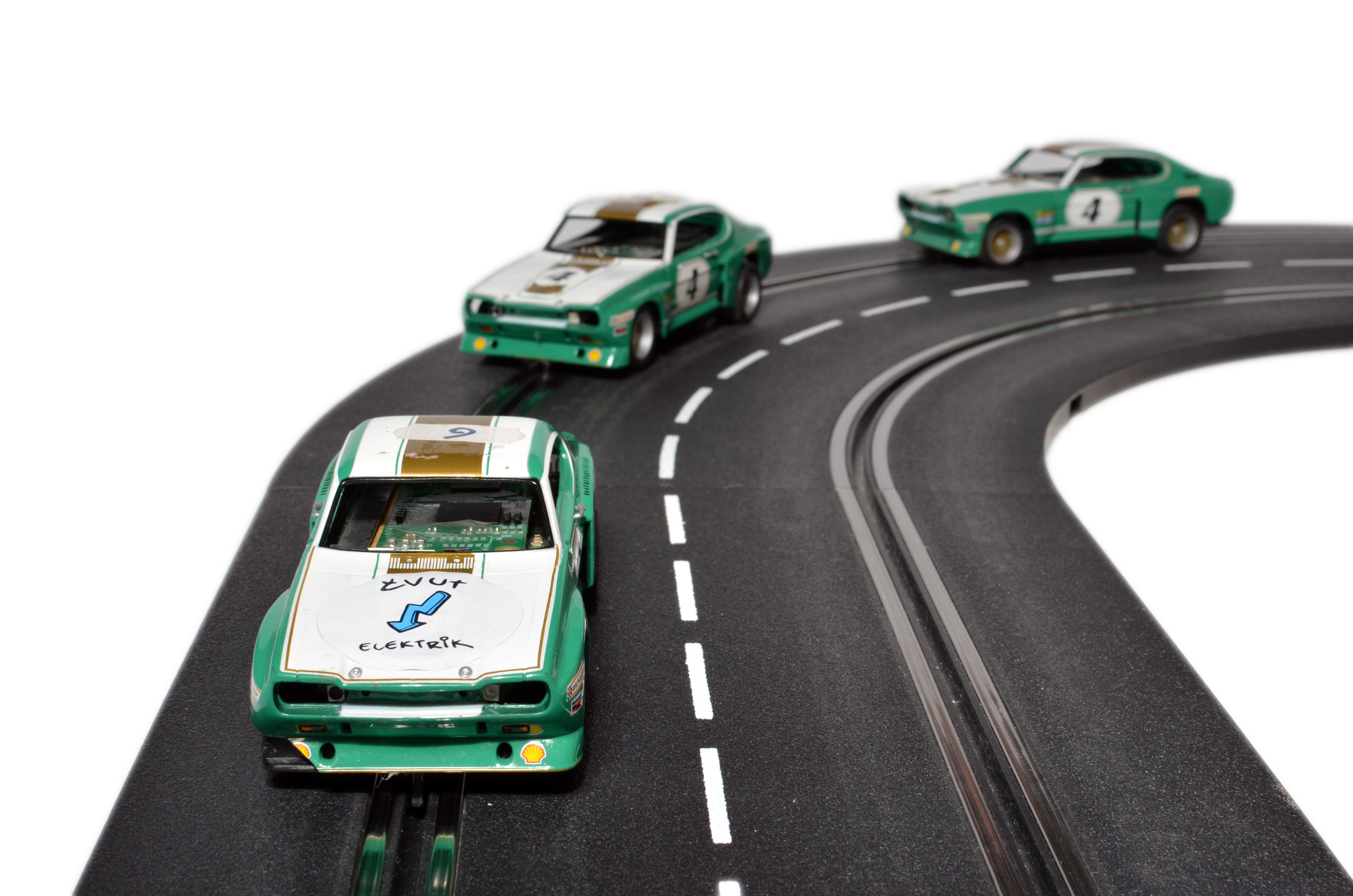
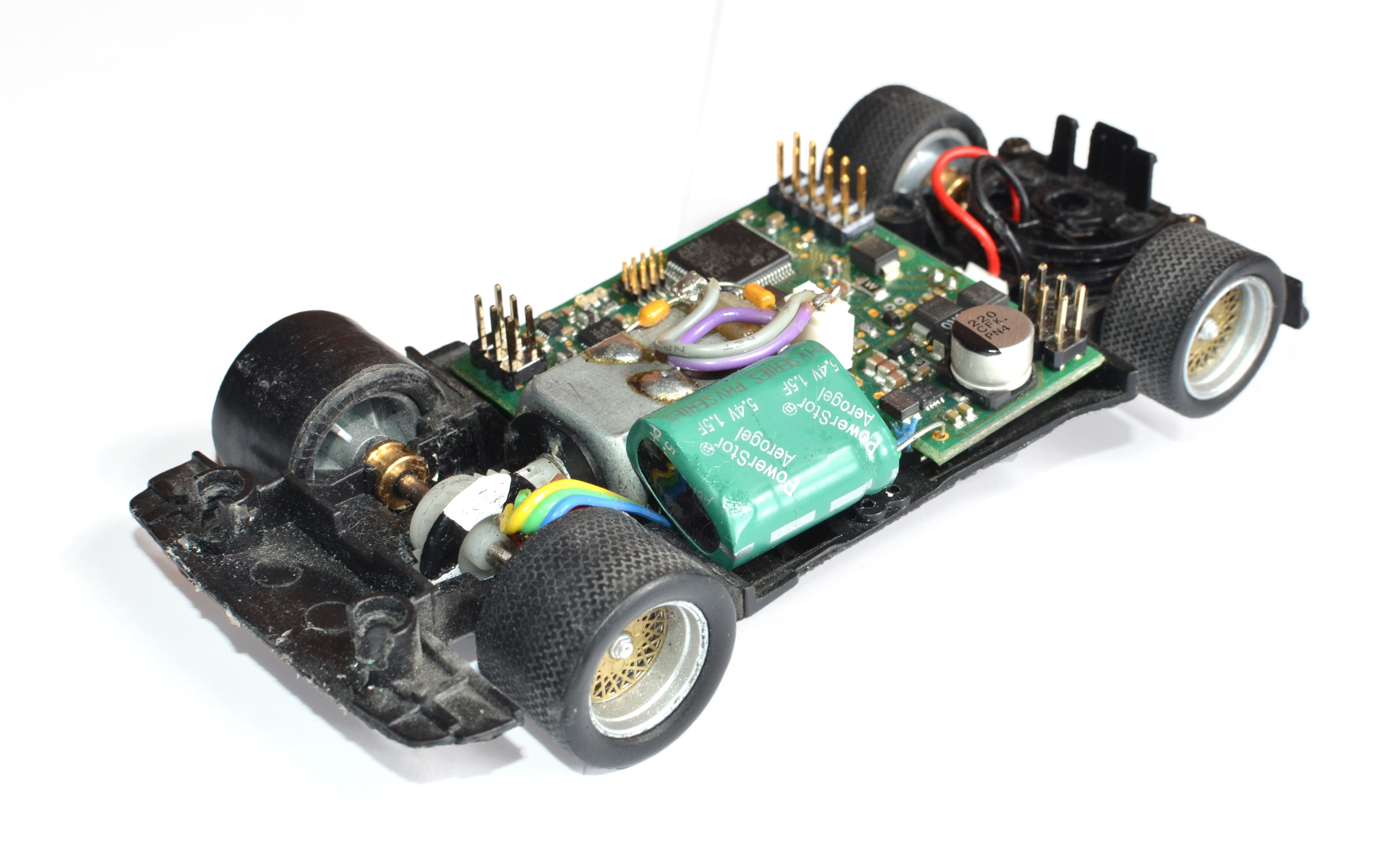
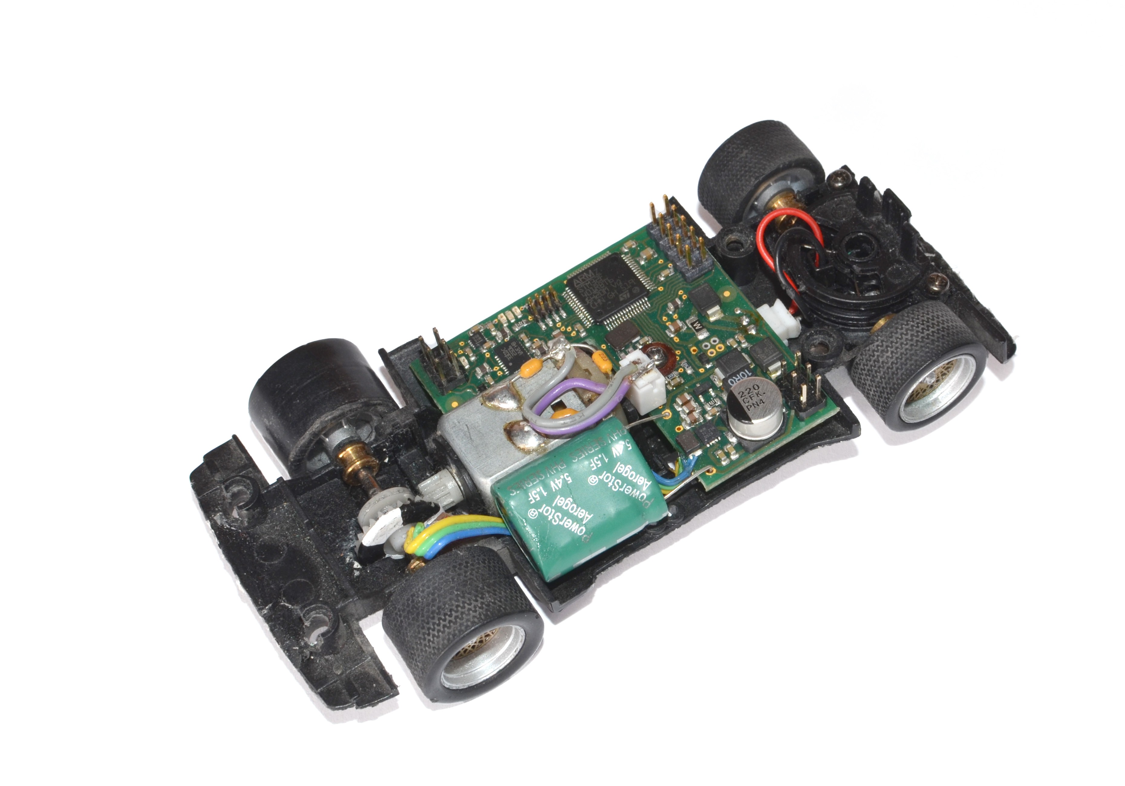
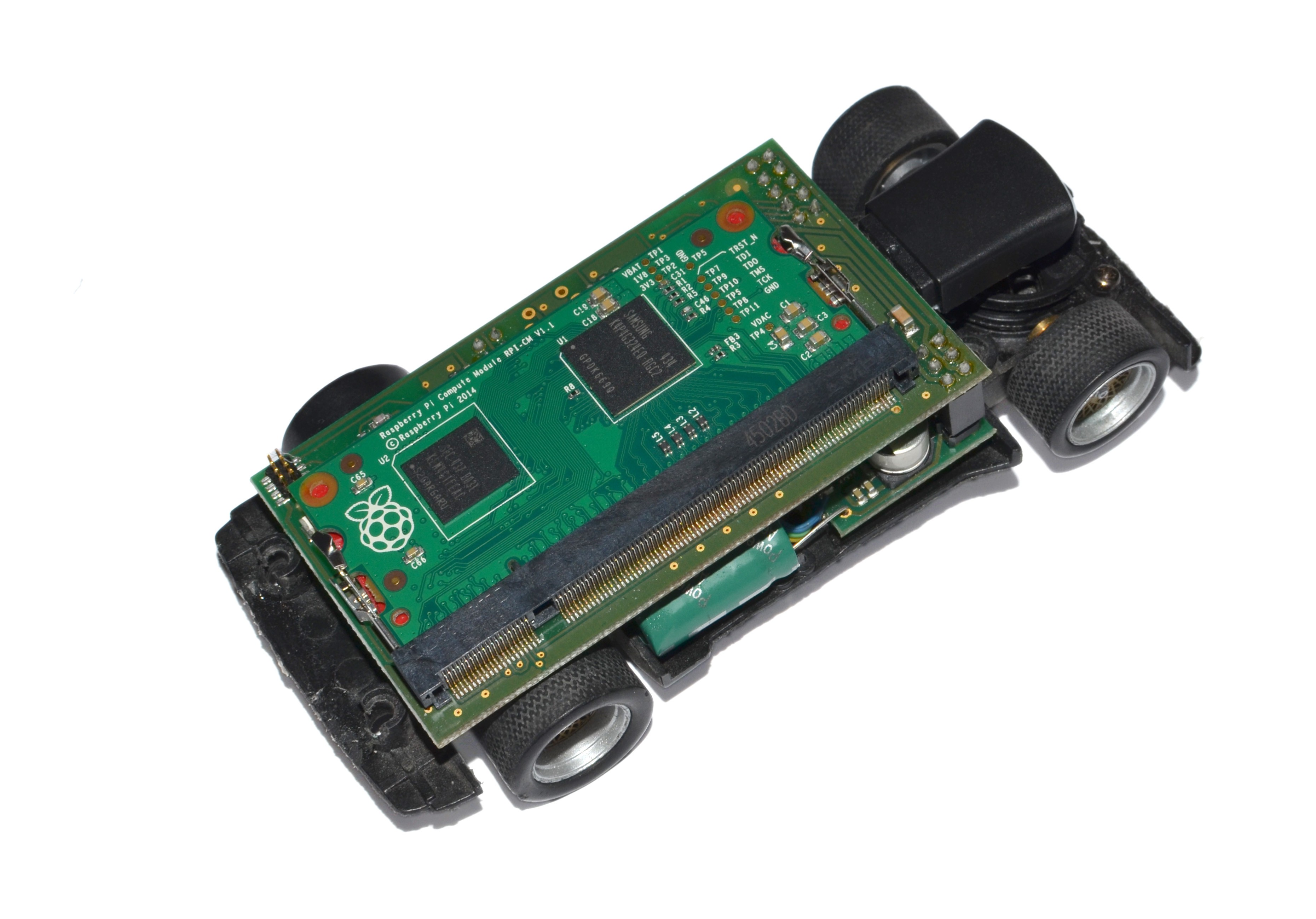
The mechanics are well known slot cars (as show on pictures below), nothing new.
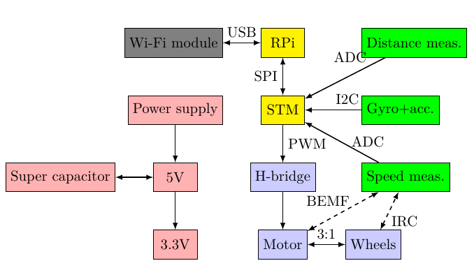
The overall electronics consists of two boards (top and bottom) and two distance sensors and one Infrared encoder (IRC).
PCB: On the top board there is the Raspberry Pi Compute Module (RPi), which is a very popular for embedded projects. It is the main computation unit. Next there is the USB connector for a Wi-Fi dongle (IEEE 802.11g), which is used as the main communication interface among all cars and with GUI/user pc. We also equipped the car with alternative communication interface Zig-Bee but we are not currently using it.
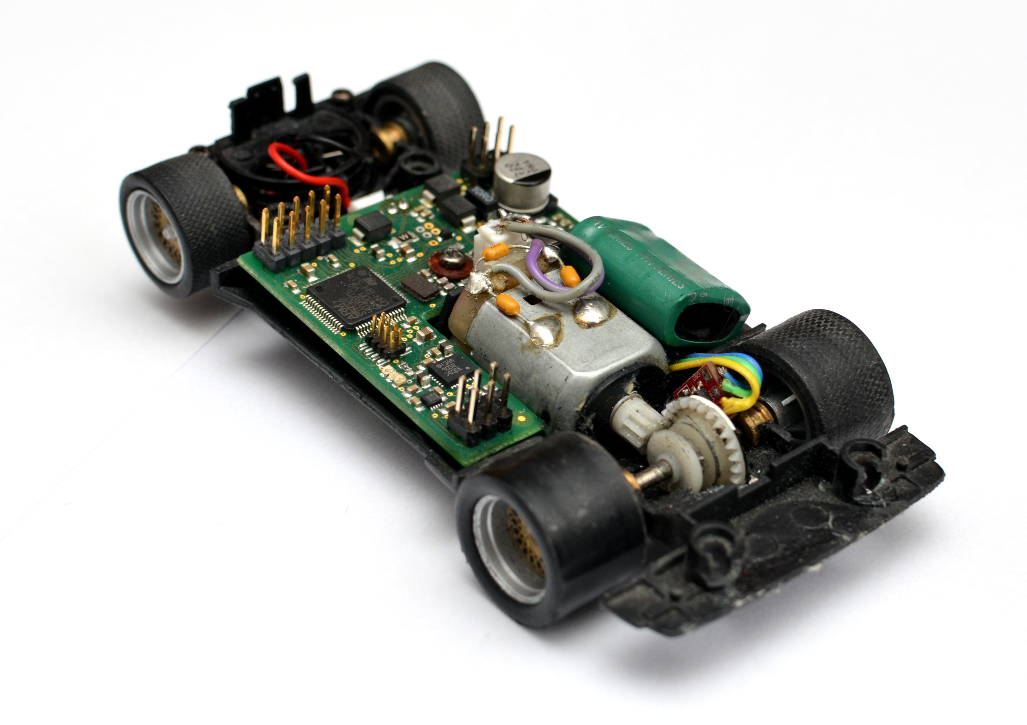
On the bottom board there is the rest of the electronics. Namely power supply chain (rail voltage (12V) → 5V → 3.3V → 1.8V), The ARM processor STM32F401 (STM), Motor driver, sensors for acceleration and rotation, magnetometer and super capacitor.
STM is there as a low level worker, who does simple yet very important job. It behaves like a sensor and low level controller for speed loop. It is a complement to RPi since it doesn't have any ADC. Moreover some measurement task needs to be done in very high frequency with precise timing, approx. from ones to tens of kHz which is not possible on RPi, because there is a non-RT OS, which can't acquire such precision. However, for purpose of controlling slower dynamical system like our car, then we are able to achieve good precision of timing compared to the period of the control loop.
There is also a 1.5F super capacitor for being a backup power supply when a loss of power happens. It backups only the digital parts not motor. It lasts for 6s.
Speed measurement is done by two methods. First is based on a homemade binary infrared encoder ( black and white circle on rear axle). The second method is based on measuring back EMF from motor, which is then multiplied by motor constant and the result is angular speed, which is then easily transferred to translation speed.
Distance sensors are based on measuring intensity of light.
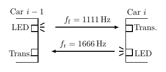
where d stands for distance, s is intensity and c is just a calibration constant.
Motor driver: Stm drives the motor by 20 kHz PWM via H-bridge. The H-bridge allows us to have the output pins also in high impedance so we can measure bemf, by having the motor flowing without being connected to the driver.
i2c sensors: accelerometer, magnetometer and gyroscope.
Software - APP
The software in the slotcar has three purposes:
- Communication with GUI. the car receives setup commands and reply.
- Communication with other cars while experiment is running. Cars communicates their states in a periodical way. They do not wait for anyone they shout over each other and therefore no order is guaranteed. It is faster enough to have a high chance that all cars will communicate at least one times per one control loop period.
- Control. The car usually control the distance to its neighbors. We consider them to be max 30cm. Also they can use others car states.
- Communication with STM. RPi reads out sensor's data and use it for control.
It runs Java controllers, which are just java classes which extends our abstract controller. These controllers are then loaded to the car and dynamically loaded by the APP.
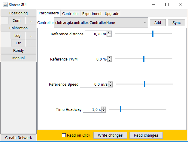
Software - GUI
It is used for maintenance and setup of the platoon.
Few features that it provides:
- Positioning: stats a positioning sequence in which all cars determine their position in the platoon.
- Com: Starts periodical communication between cars.
- Calibration: calibrates distance sensors.
- Ctr: starts control.
- Setting cars references
- Setting controllers constants (which are public fields in java class)
- Upgrade tab where most common task for maintenance are held.
- and more...
Model and controls
Please refer to the conference paper.