As the prototype worked better than expected, clearly I needed to make something more robust and useful.
Ideally mechanically solid, in a case, powered by a 12V wall wart, coax connection to scope and generally a lot nicer.
450A/V is going to be useful for someone, I quite often deal with currents of that magnitude at work however I don't at home and I suspect that few do. Clearly we need some amplification on the output to get it to be useful. X20 would get us to around 22A/V which would be a lot more useful for most people.
I had a useful little box from an old lamp, lots of cheap TL431 ICs of dubious origin (I have no idea who made them but I suspect it's not anyone that i've heard of before, my coil from the prototype amd connectors for 12V and coax. Conveniently I can use a TL431 as a regulator (how dull) to get a stable 5V to run the circuit. Because of how the TL431 works in these circuits I probably didn't need to add the regulator. Oh well, too late now.
Looking through my box of miscellaneous opamps, one thing became clear. I didn't have any suitable opamps for the amplifier. Either too slow, far too fast or too big (box is small). Solution: use a TL431! They've got reasonable bandwidth, I have loads and the three pin package is so easy to use.
I added a common collector amplifier to boost the current/isolate the tl431 circuit from the coax and then called it a day. Sadly I ran out of space to fit the final AC coupling capacitor so it has to be ac coupled on the scope.
Circuit:
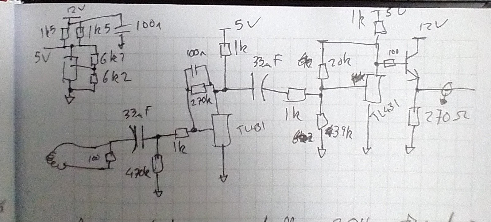
The regulator is in the top left, basic shunt regulator.
The interesting bit is below, starting with the coil on the left and ending at coax on the right.
After the coil is the AC coupled TL431 integrator. The 470k is there for setting the DC bias point which is roughly 3.8V. The 1k and 270k set the maximum AC gain (270x) and the 100n and 270k set the integrator minimum frequency. The TL431 needs at least 1mA so the 1k sets the quiecent current at just over 1mA.
Again it's AC coupled followed by the 20x gain amplifier. Again the output bias point is around 3.8V.
Finally we have the emitter follower that provides current amplification for driving 50R coax. Since this was never going to be particularly high frequency I didn't bother with 50R matching.
PCB
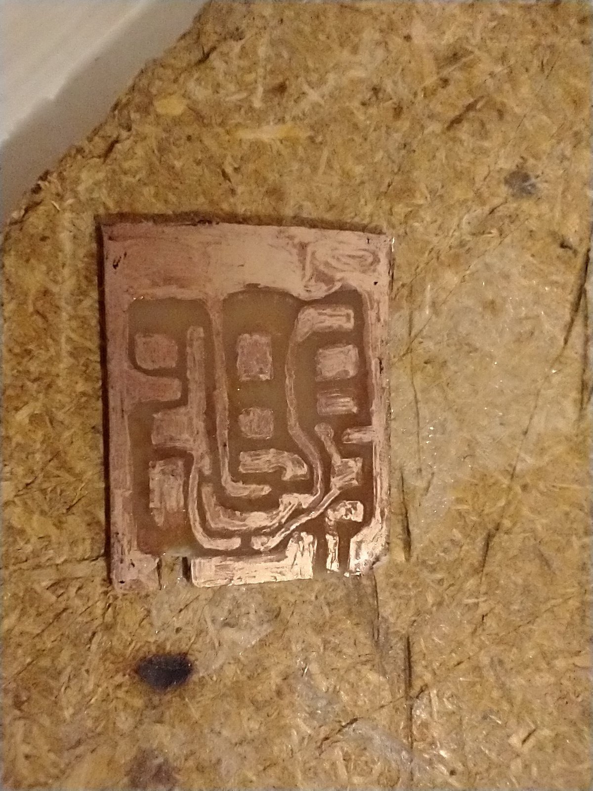
Hand drawn with a Sharpie, etched with ferric chloride.
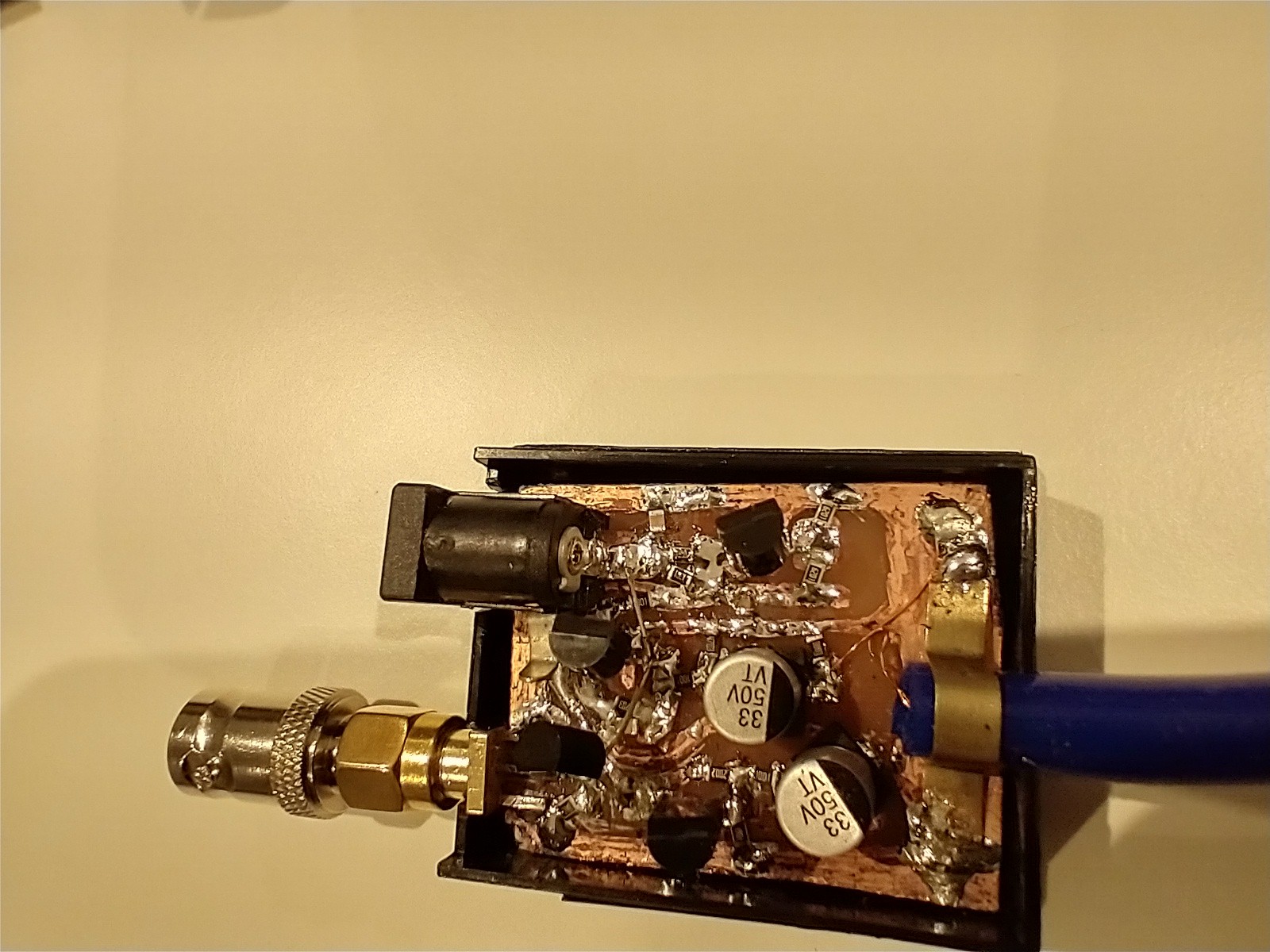
Populated and assembled. Only one bodge as I didn't initially plan to fit the emitter follower.
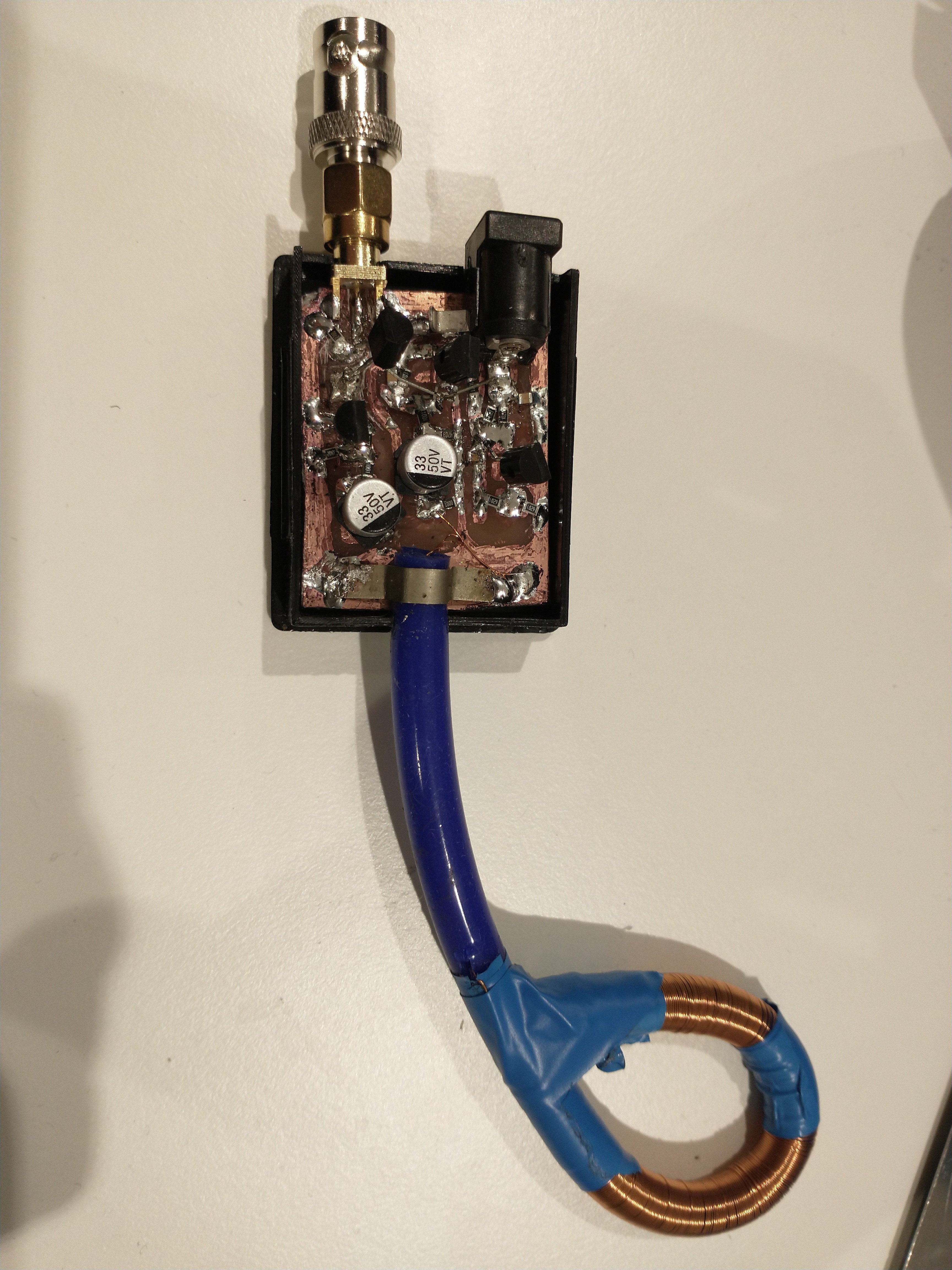
Showing the coil. It's held closed with electrical tape.
Discussions
Become a Hackaday.io Member
Create an account to leave a comment. Already have an account? Log In.