First up, let's have the completed unit with the power supply short circuit test.
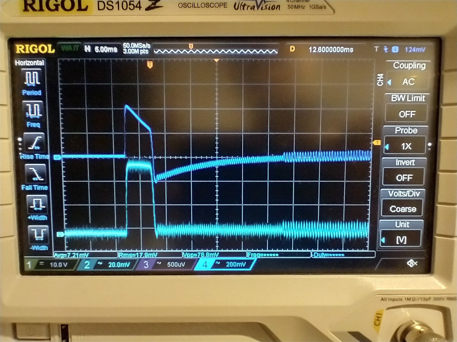
Blue channel 4 is the Rogowski coil, cyan channel 2 is the LEM HAIS 150-P hall effect sensor which is 4.2mV/A. We can see that the current is a short pulse of around 5ms. The Rogowski coil is showing the result of a high pass filter of around 30Hz. What's really satisfying is that it tracks the higher frequency oscillations very well. They're at a few kHz.
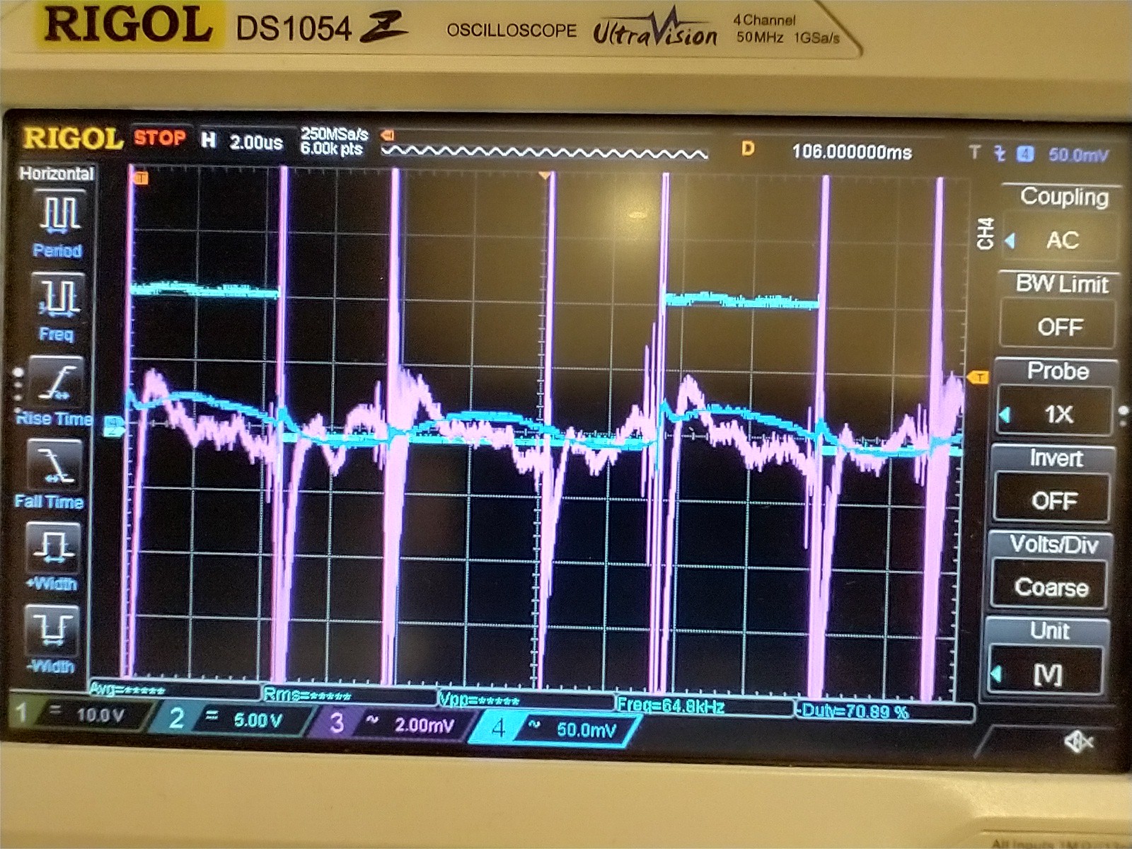
This one isn't so pretty. I've got a messy bodged together multilevel dcdc converter that's got a couple of amps peak to peak of ripple in the inductor at 100kHz.
The square wave on channel 2 is a half bridge output, magenta (channel 3) is the output of the integrator and blue (channel 4) is the output of the amplifier. I suspect a lot of the noise on the integrator is poor probing but not all of it. The amplifier appears to have cleared it up nicely. Clearly we're beyond the -3dB point as it's mostly sinesoidal instead of triangular. A datasheet for the TL431 suggested a bit over 1MHz unit gain bandwidth. This one is running at 20x so we'd expect around 50kHz for the low pass cut off frequency.
What the second plot is showing is that the TL431 makes a great integrator but isn't a great opamp for amplification. If I wanted this for dcdc work then I'd need at least 1MHz bandwidth (probably more like 10MHz) so I should probably use a proper opamp on the next one.
Discussions
Become a Hackaday.io Member
Create an account to leave a comment. Already have an account? Log In.