Introduction
Op amps are well known for their utilitarian prowess, performing many vital tasks underpinning analog circuit design. They add, subtract, integrate, differentiate, and amplify with great precision!
That’s all well and good… but how about the arts? Can an op amp create a drawing? That’s the essence of this project. Let’s see what we can do!
At first glance, op amps don’t seem to be the right tool for the job. But then they can perform mathematical operations, and math often generates visually appealing results. Examples are fractals, Lissajous curves, and even the positioning of seeds in a sunflower blossom!
For this project, we’ll focus on curves called hypertrochoids and epitrochoids. These curves are produced by the well known Spirograph toy and produce all sorts of interesting patterns. As it turns out they can be generated by summing sinusoids of various frequencies and magnitudes. This is well within the capability of the mighty op amp!
Op Art's features include:
- Generates both hypotrochoids and epitrochoids
- Op amp & passive circuits only
- Battery operation - two AAA alkaline or rechargeable cells
- Display using oscilloscope - via two BNC test cables
Spiro-Math
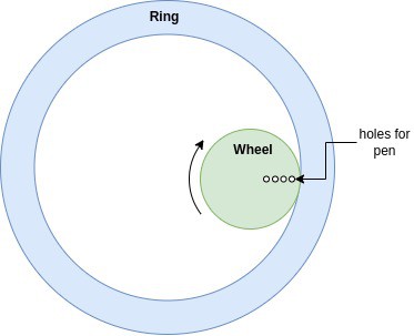
Op Art generates curves that can be created with the age-old Spirograph toy, which I had a lot of fun with as a child. For those who are not familiar, a Spirograph toy has two main parts - a ring and a wheel. The wheel has several holes into which a pen tip can be pressed. You place the wheel inside the ring, set a pen tip in one of the wheel's holes, and then roll the wheel along the inner perimeter of the ring. As the wheel rolls, it traces out a pattern. You can change the pattern by moving the pen to a different hole in the wheel, selecting a different size wheel, or even rolling the wheel on the outer perimeter of the ring. There are gear teeth on both the ring and wheel which keep them from slipping. The figure below shows the geometry of Spirograph.
To study the mathematics behind the Spirograph, we'll look at a simplified geometry shown below. The geometry consists of a circle within another circle. The inner circle rolls inside the perimeter of the outer circle without slipping. The inner circle has a red point indicating the position of a pen. The resulting curves traced out by the pen (red dot) are called hypotrochoids.
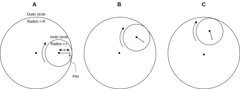
The inner circle's starting position is shown at left in column "A" of the figure above. The inner circle is then rolled clockwise, reaching the position in column "B", then the position in column "C", and so on.
If you look closely at the diagram you might notice that the pen's path follows two connected line segments or vectors. The first vector extends from the center of the small circle to the pen's position. It rotates clockwise around the center of the small circle. The second vector extends from the large circle's center to the small circles center. It rotates counterclockwise around the center of the large circle. The two vectors, which we'll call O and I are shown below.
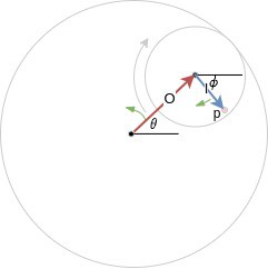
The pen position is simply the vector sum of O and I. So if we can describe both vectors, we can calculate the path that the pen takes. The magnitudes of the vectors O and I are pretty straightforward to find. I's magnitude is simply the pen position "d" defined in the previous figure. O's magnitude is the outer circle radius minus the inner circle radius, or R-r.
O's angle is defined as θ in the diagram. I's angle is shown as ɸ, however, it is dependent on θ and the geometry of the Spirograph. The relation between θ and ɸ can be found by equating arc lengths on the inner and outer circles. Reference [1] shows how, and provides the relation ɸ = θ * (R-r)/r.
With the magnitudes and phases defined, we can write out the x and y coordinates of the vectors as:
Vector O: x = (R-r) * cos(θ) , y = (R-r) * sin(θ)
Vector I: x = d * cos(θ*(R-r)/r), y = - d * sin(θ*(R-r)/r)
The final step is taking the vector sum of O and I. This provides a set of parametric equations describing the pen's path. The resulting curves are called hypotrochoids:
x = (R-r) * cos(θ) + d * cos(θ*(R-r)/r)
y = (R-r) * sin(θ) - d * sin(θ*(R-r)/r)
The Spirograph can create another set of curves by rolling the wheel on the outer perimeter of the ring. This similarly leads to a pattern traced out by the sum of two rotating vectors. However, in this case, both vectors rotate in the same direction. The resulting curves are known as epitrochoids, which are described by the following parametric equations [2]:
x = (R+r) * cos(θ) - d * cos(θ*(R+r)/r)
y = (R+r) * sin(θ) - d * sin(θ*(R+r)/r)
In summary, the Spirograph generates two classes of curves - hypotrochoids and epitrochoids. Both sets can be generated by summing together a pair of rotating vectors. In the next section, we'll discuss how to implement these classes of curves with an op amp circuit.
Circuit Design
Armed with an understanding of hypotrochoid and epitrochoids, we're now ready to brainstorm circuit designs. It'll help to think of the vector sums that we discusses in the previous section. Since both classes of curves can be described as the sum of two vectors, we can think of one vector at a time. We'll also have to put blinders on and think in terms of only analog and mostly linear circuits, since we're trying to build this with op amps.
Back to the vectors. Let's start with the O vector in a hypotrochoid. It has a constant magnitude of R-r and an angle θ. The angle θ increases as the Spirograph's wheel rolls, causing this vector to rotate counterclockwise. Assuming constant speed, we can define θ as a function of time (t) and frequency (f1): θ = 2π*f1*t. The vector's parametric equations as a function of time t are:
x(t) = (R-r) * cos(2π*f1*t)
y(t) = (R-r) * sin(2π*f1*t)
The second vector, I, can be described similarly, but has reversed rotation, along with a different magnitude and frequency. It's parametric equations are shown below. The negative sine term handles the reversed rotation.
x(t) = d * cos(2π*f2t)
y(t) = - d * sin(2π*f2*t)
Both parametric equations can be generated with oscillators. Since they're at different frequencies, we'll factor on using two oscillators. Further, we need to vary the frequency of at least one oscillator to simulate the effect of changing the size of the Spirograph wheel.
We now have all of our sines and cosines. All that we need to do now is scale and sum them together. Finally, we can buffer the resulting sum for input to an oscilloscope.
Oh, we forgot one thing . . . epitrochoids, the curves that are created when the Spirograph wheel rolls on the outside of the ring. Luckily their equations are very similar. The main difference is that they are described by two vectors rotating in the same direction, rather than in opposite directions. We can account for this by generating both positive and negative sine waves, and switching between the two... with,,, you guessed it, a switch!
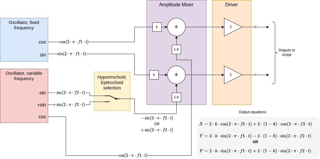
The diagram below brings all of the concepts together. At left are two oscillators - one with a fixed frequency, generating sines and cosines for the O vector, and one with a variable frequency, generating sines and cosines for the I vector. Just to the right of the variable frequency oscillator is a switch which selects either a positive or negative sine. This allows the user to select either hypotrochoids or epitrochoids. Next in the purple block is the Amplitude Mixer, which adds the x and y components of the O and I vectors. It also scales the components, which is an electronic equivalent of changing the wheel size and pen position. Finally, the rightmost block is an output Driver for interfacing to the oscilloscope. It consists of a pair of buffers.
Circuit Implementation
With a block diagram in hand, we have a good idea of how to build this circuit. We can now move on to the details of the implementation. There are four blocks that need implementing:
- Oscillators - One fixed frequency frequency, and one adjustable. They will need quadrature outputs.
- Switch - To swap between hypertrochoids and epitrochoids.
- Amplitude mixer - Sums the oscillator sin and cos outputs, and adjusts their relative magnitudes.
- Driver - Output interface to the oscilloscope.
We'll start with the trickiest part - the oscillators. Since we need both sines and cosines, my first thought was to use quadrature oscillators. Its a pretty well known circuit for producing separate sine and cosine outputs, so it seemed to be a natural fit. I went ahead and breadboarded one. It worked beautifully. . . that is until I tried to adjust its frequency using a dual potentiometer. It went in and out of saturation and oscillation during adjustment. It turns out that quadrature oscillators are not practical for variable frequency. They rely on two integrators, each providing 90° out of the total 360° at the frequency of oscillation. At first glance it seems that you can adjust the resistor values in the integrators to vary the frequency. The issue is that the magnitude of an integral of a sinusoid is proportional to frequency. Thus changing these resistors also significantly alters the loop gain at the resonant frequency. Without also updating the inverters gain and maybe the limiter too, you'll run into trouble.
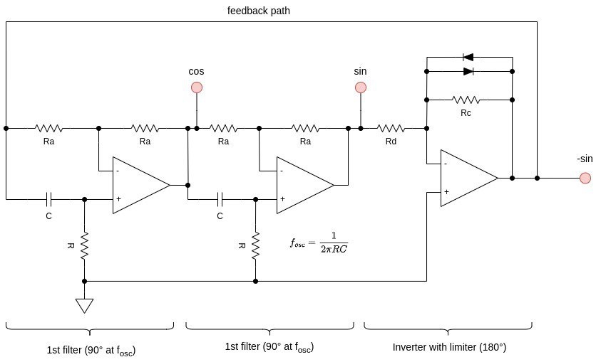
So, back to the drawing board... After some research I came upon a phase shift oscillator design that was up to the task. It's used as the basis of the Miniosc project on the Elliot Sound Products website, and originally introduced in Wireless World magazine [3,4]. Instead of integrators, this oscillator uses two all-pass filter networks, each providing 90° of phase shift at the resonant frequency. The filters are followed with an inverter providing an additional 180° of phase shift. The all pass filters have constant gain across frequency, and vary only in phase with frequency. Their 90° phase point can be adjusted with two resistors, and doing so does not mess up the oscillator's closed loop gain.
Here's a schematic of the basis oscillator design. You'll note the two identical all-pass filters, followed by an inverting amplifier. The frequency is set by adjusting the two "R" or "C" values. There are actually three sinusoidal outputs at 0°, 90°, and 180° relative to each other, which I've labelled "cos", "sin", and "-sin". Op Art will make use of all three outputs. The two diodes in the inverting amplifier serve as a limiter to keep the oscillator from saturating at the supply rails. When the output voltage approaches the diode forward voltage, one diode will start to conduct, cutting back the oscillator's gain. This results in an output of about 0.7Vpp. There will be some distortion with this simple limiter. I added some series resistance to the diodes in the full circuit design to limit the distortion a bit and called it good enough.
We can use the above circuit for generating the fixed frequency output, representing the O vector. For the other vector, we'll want to add frequency adjustment so that we can control the relative frequency of the two vectors - our way of changing the Spirograph wheel size. To do so I added a dual gang potentiometer in series with the two resistors labelled "R".
Next up up is the switch, which I just used a simple mechanical switch configured as SPDT. That was easy!
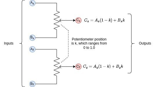
The second to last item is the amplitude mixer. This one is pretty simple too. We need to simultaneously mix the x and y components. I used a dual-gang potentiometer, with one gang for the x components and the other for the y components. The set is shown below.
The final subsystem are the output buffers. The buffers isolate the high impedance output of the mixer and serve as an interface to the oscilloscope. They also add some gain to boost the signal voltage. I implemented them with non-inverting op amp amplifiers. The outputs are connected to 1kΩ resistors to isolate the op amp outputs from the coaxial cable capacitance. This scheme works fine for the sub 10kHz frequencies generated by the circuit.
Powering It Up
One thing I didn't mention in the system design is Op Art's power needs. The main goal is to be able to run it off of a couple AAA batteries for many hours. It also should have a switch and a power indicator LED so I don't forget to turn it off. It should work with both alkaline and rechargeable NiMH cells. The rough requirements are thus:
- Operation from two AAA cells (rechargeable NiMH or alkaline)
- LED power indicator & switch
- Operates with battery voltage of 1.0V or less (minimum for a NiMH cell that's nearly discharged)
- Long battery life (many hours) -> max current of ~10mA since AAA NiMH cells capacity is about 800mAH
For the sake of simplicity it would also be nice to run the circuits right off of battery voltage. This avoids a boost converter or even a regulator. Luckily CMOS op amps are up to the task, with many rail-to-rail parts that can operate below 2.0V - the worst-case, considering two series NiMH rechargeable AAA batteries.
With all those op amps (eight of them to be exact), is this thing going to be a power hog? CMOS op amps to the rescue again! They sport quite low power consumption. I selected the Microchip MCP6004 quad op amp. Its quiescent current is 100uA typical per amplifier. Op Art uses two MCP6004's, leading to an expected typical quiescent current of only 800uA.
The other consumer of power that's easy to overlook is the power LED. I ran it at about 0.2mA to conserve power and found that it was still plenty bright enough.
Adding it all up, we expect slightly greater than 1mA of current draw from the batteries. This is based on the op amp quiescent current, LED current, plus some margin for power dissipated in the op amp output stages and various resistors in the circuit. This should provide several weeks of continuous operation. To verify, I included resistors for current sensing. The first such resistor is R22, which is in series with BT1, the AAA battery providing the positive supply rail. The second one, R24, is in series with BT2, which provides the negative voltage rail. They both have test points at each end for probing with a multimeter.
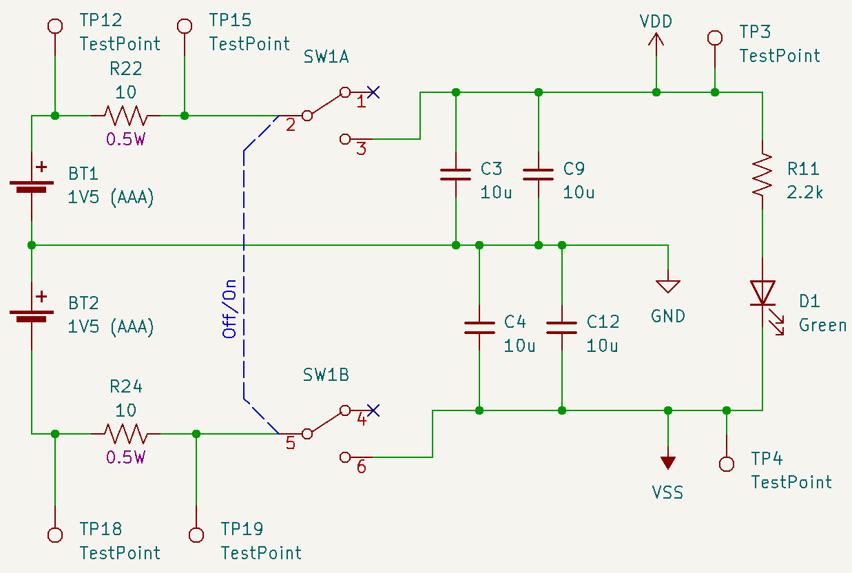
To test power consumption, I installed two 800mAh NiMH AAA batteries in OpArt. I powered up Op Art and set it up as it is normally operated, with its X and Y outputs connected to scope inputs. Both AAA batteries measured about 1.33V during operation. I then monitored the voltage across the two sense resistors R22 and R24 using a true RMS multimeter. The measured voltages and corresponding currents are shown in the table below. The currents are nearly equal as I expected, and both well within the requirement for 10mA current or less. The estimated battery life for the 800mAh NiMH cells is about 700 hours. Not too bad!
| Sense Resistor | Measured voltage | Current | Estimated lifetime, 800mAh AAA |
|---|---|---|---|
| R22 (series with BT1) | 11.4mV | 1.14mA | 702 hours / 29.2 days |
| R24 (series with BT2) | 11.5mV | 1.15mA | 696 hours / 29.0 days |
References
[1] The Hypotrochoid By Craig Anderson
[3] Elliot Sound Products Miniatuer Audio Oscillator Project
[4] Phase-shifting oscillator, Wireless World, Feb 1982, Roger Rosens
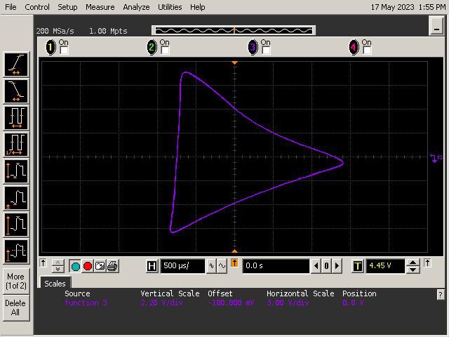
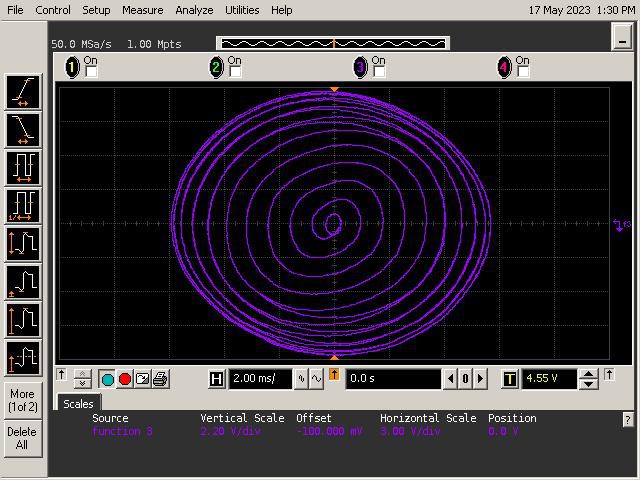
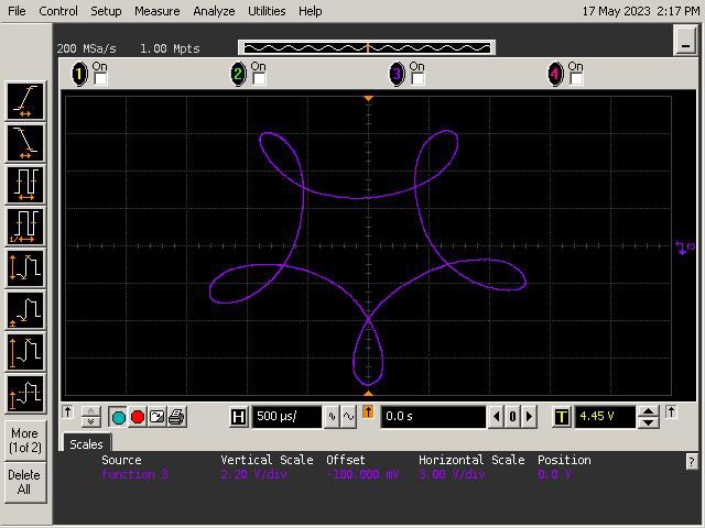
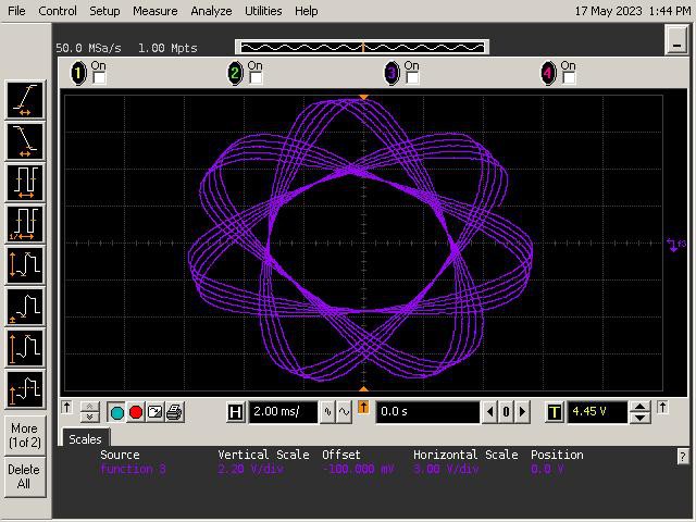
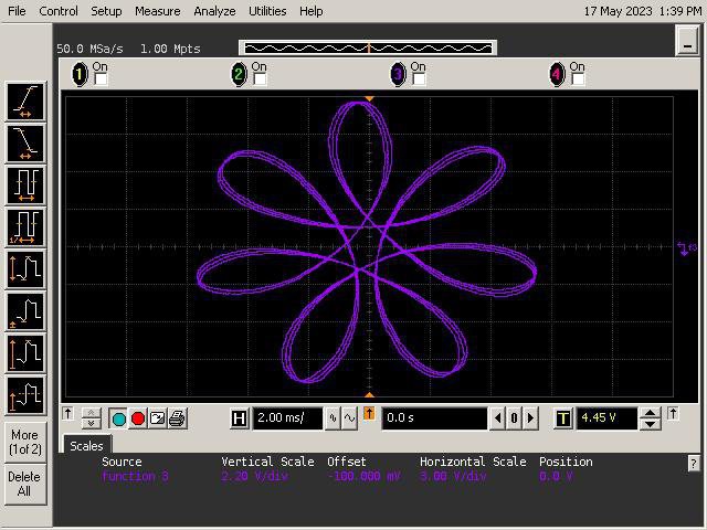
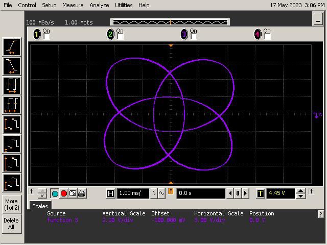
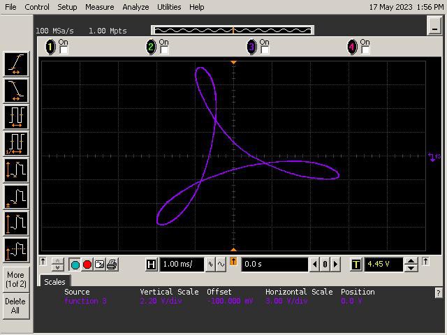
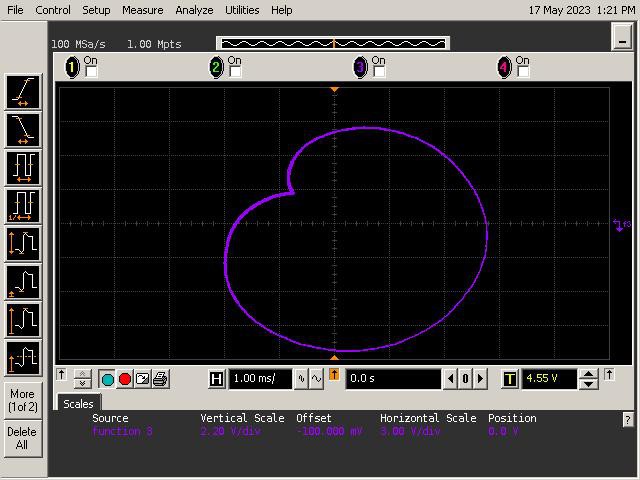
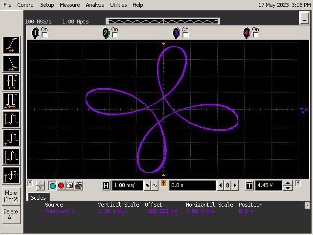
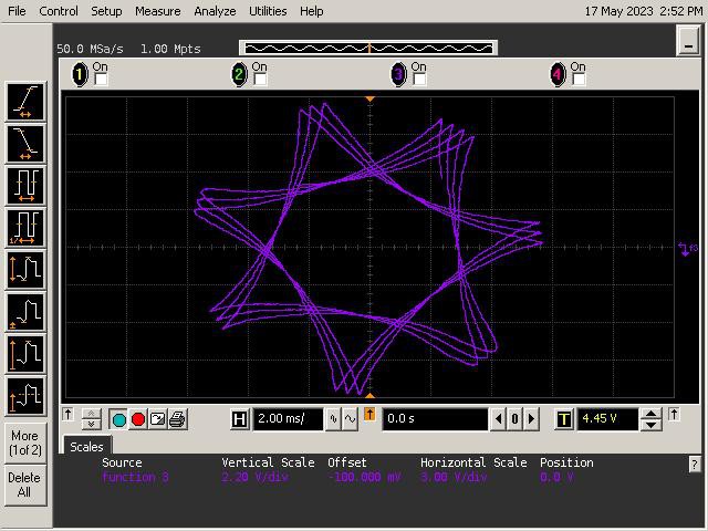
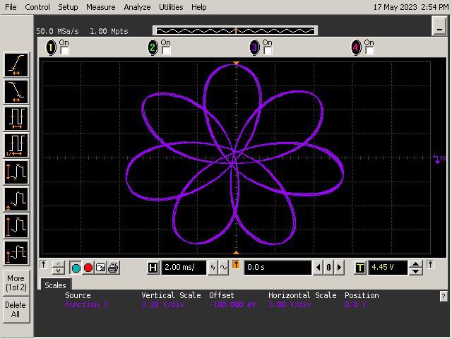
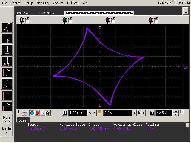
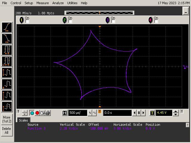
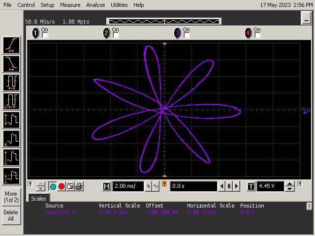
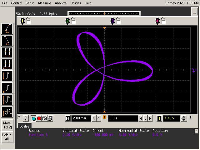
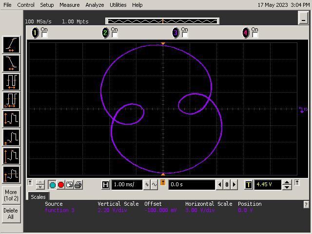
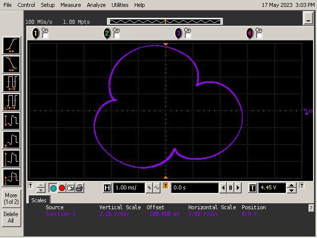
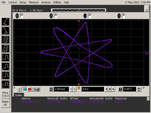
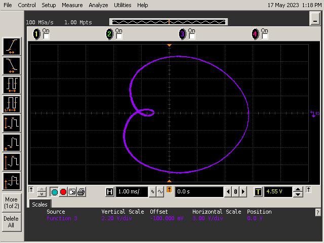
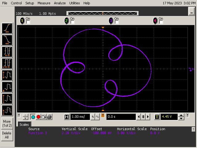
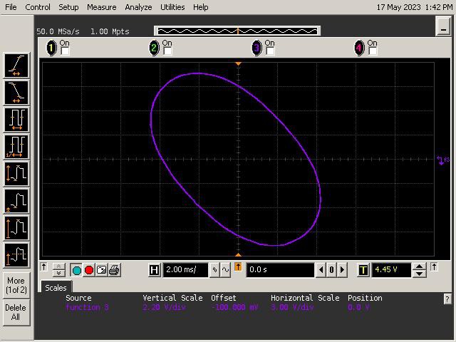
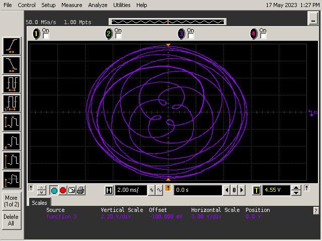
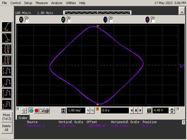
Let's See What It Can Do!
See below for some of Op Art's art. Refer to the instructions section of the project for guidance on generating patterns.