 xpDIY
xpDIYSometime ago I introduced the auto cassette feeder, which come with proximity sensor. And since the baseplate doesn’t come with power, I use the battery to power the feeder.
Then I got suggestion why not provide power with baseplate, then there is no need to use battery and lower down the cost. I think this is a really good idea, so I started designing the system. To provide the power it is quite straight forward, initially I am thinking putting strips between Lego bumps and then implement 2 pogo pins in the feeder for power connection, which is simple! But then the dark side of my engineering brain come in and raise the voice of why not provide the position info as well, I think everybody who play with pick and place machine at some point thought about an automatic positioning system, so that setting up feeder and other component will be easier. So I started designing. The first challenge is how to make contact to the components (feeders, fiducial, camera., etc), I don’t want to change the base plate too much, I hope the component can still use the baseplate without modification. With that in mind, I finally decided to use Lego bump as the fixture, and make baseplate PCB strip a Lego component as well.
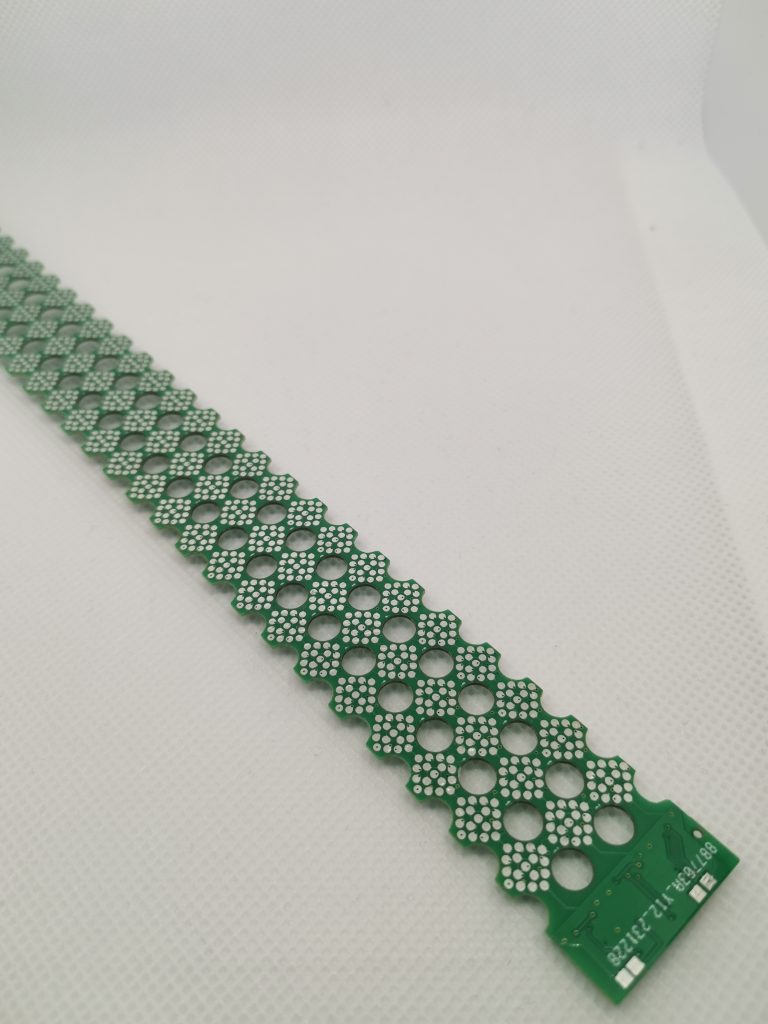
The second challenge is how to make sure the contact is good enough. After checking different components and considering the space limitation (between Lego bumps), I found POGO pins are really good candidate. It is design to use for such case and can hold >10000 times plug in and out. With 10 times plug in and out per day, it can hold around 3 years, if 5 time per day, it can be around 6 years. So with that, I think it will fit most of use cases.
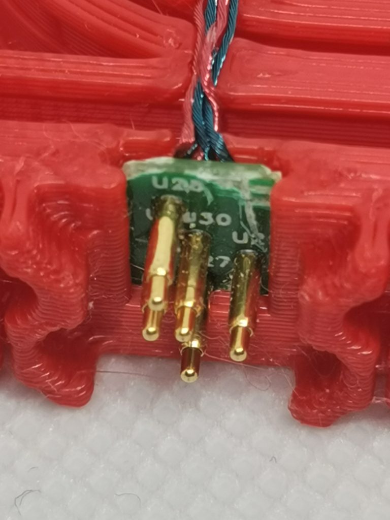
Then for the third challenge, how to provide position info, how many pins needed. Considering the limited space, the less signal, the better. In order to get position, the first idea is to put the EEPROM chip with one wire protocol, that can be read from the control board. But this requires control to know which EEPROM corresponding to which location, and also the solution is more expensive. After consideration, a resistor dividing solution is selected. To know the position, it is simply an ADC with calculation. And the same solution can be apply for both row and column in order to finally determine the location. Finally I decided to go for 5 pin solution, VCC, GND, 1wire, ROW, COL. The 1 wire pin is required to send the position info to control board after reading the row and column info from ADC.
Another challenge is to add support for openpnp. I have been using the ReferencePushPull feeder from openpnp. I like the feature of automatically calibrate the pick position and then pick. Because the auto positioning can have certain tolerance, with the auto calibration, it is able to make sure the pick action can be done accurately. So I have inherited the feeder, and provide the position setup feature to it. You can refer to video
Finally the control board, it is the bridge between the components and Openpnp. I have implemented several G-Code command in order for Openpnp to interact. In the mean time, within feeder or other component, to make things easier, I also implemented the same gcode, so that for control board, it is easier to just forward the command to achieve different functionality. You can find detail here

I am pretty happy with the current design. Still some improvement are coming, for ex. I am planning to implement orientation detection feature, also I plan to put the position aware feature to fiducial, so that it is able to calibrate the baseplate offset automatically. Stay tuned!
Discussions
Become a Hackaday.io Member
Create an account to leave a comment. Already have an account? Log In.