 kutluhan_aktar
Therefore, establishing an efficient and accurate pipeline diagnostics mechanism conforming to general maintenance regulations can assist technicians in keeping machines durable far more than anticipated and prevent companies from squandering their resources on replacing or repairing high-value machine components due to the omission of proper pipeline diagnostics.
Pipe cracks are one of the most common defects while transferring liquids, especially with differing thermal conditions. During machine operations, mechanical and thermal stress cause minute defects in pipelines due to fatigue. When these small defects accumulate, the outcome mostly results in a varying inside turbulent pressure, which leads to slight form (shape) disfigurations, resulting in gradual deficiency over time due to tension. Furthermore, depending on operation processes and environment, there are lots of possible pipeline defects in addition to cracks, such as corrosion, abrasion, clogged joints due to chemical residue, leaking connection points due to high gas emissions, etc.
Although there are different external pipeline inspection devices utilizing computer vision (camera), magnetic field measurements, and acoustic detection (microphone)[1], these methods cannot be applied interchangeably to different pipeline systems. For instance, a device utilizing object detection with a thermal camera may not be able to detect internal crystals due to high gas permeability in a pipeline system transporting antifreeze to cool components.
Nonetheless, some groundbreaking new methods aim to detect potential pipeline system failures by examining changes in the vibration characteristics. Since accumulating stress due to pipeline defects affects material integrity and structure gradually, these failures can be detected by inspecting fluctuating vibrations as a non-destructive testing and evaluation (NDT&E) mechanism. For example, in recent examinations, researchers applied ground penetrating radar (GPR) to detect cracks in a buried pipe[2] and microwave-based synthetic aperture radar (SAR) to inspect pipeline defects[3].
After perusing recent research papers on pipeline diagnostics based on vibrations, I noticed there are nearly no appliances focusing on collecting data from a mmWave radar module to extract data parameters, detecting potential pipeline defects, and providing real-time detection results with captured images of the deformed pipes for further examination. Therefore, I decided to build a budget-friendly and compact mechanism to diagnose pipeline defects with machine learning and inform the user of the model detection results with captured images of the deformed pipes simultaneously, in the hope of assisting businesses in keeping machines durable and stable by eliminating basic pipeline defects.
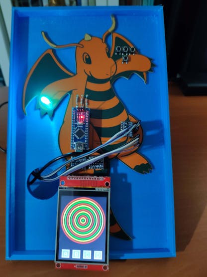
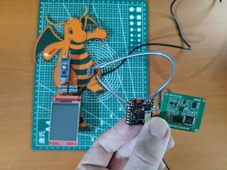
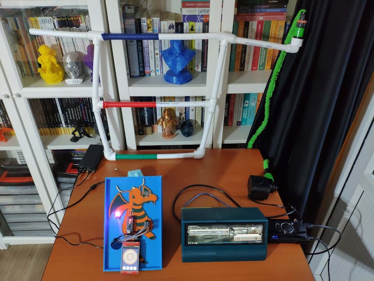
To diagnose different pipeline defects, I needed to collect accurate vibration measurements from a pipeline system so as to train my neural network model with notable validity. Therefore, I decided to build a simple pipeline system by utilizing pipes and fittings (adapters) with mediocre thermal conductivity, demonstrating three different pipeline defects in each primary section — color-coded. Since Seeed Studio provides mmWave radar modules with built-in algorithms to detect minute vibration changes to evaluate respiratory rate, heart rate, and sleep status, I decided to utilize a 60GHz mmWave module to extract my data parameters via the mentioned algorithms. Since Arduino Nicla Vision is a ready-to-use and compact edge device with a 2MP color camera and integrated WiFi/BLE connectivity, I decided to use Nicla Vision so as to run my neural network model, capture images of the deformed pipes, and inform the user of the model detection results with the captured pipe images. Due to architecture and library incompatibilities, I connected the mmWave module to Arduino Nano in order to extract and transmit radar data parameters to Nicla Vision via serial communication. Then, I connected four control buttons to Arduino Nano to send commands with the collected mmWave data parameters to Nicla Vision. Also, I added an ILI9341 TFT LCD screen to display the interface menu, including a custom radar indicator.
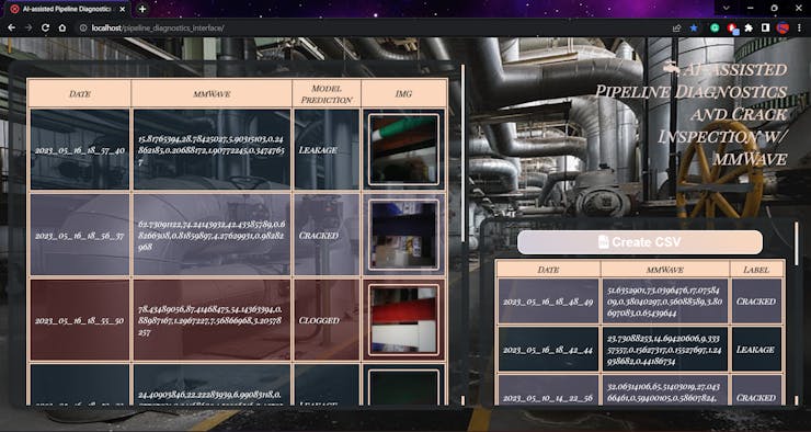
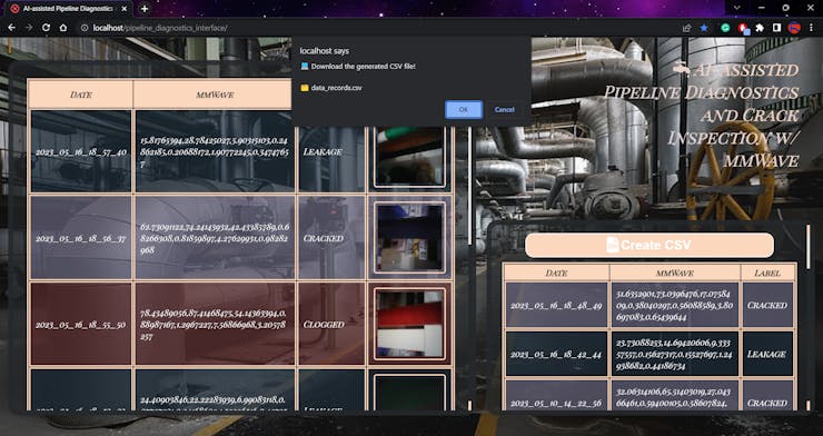
Since I focused on building a full-fledged AIoT device diagnosing pipeline system defects, I decided to develop a web application from scratch providing various features to the user. Firstly, I employed the web application to obtain the collected mmWave data parameters with the selected label from Nicla Vision via an HTTP GET request, save the received information to a MySQL database table, and display the stored data records on its interface in descending order. Via a single HTML button on the interface, the web application can also generate a pre-formatted CSV file from the stored data records in the database without requiring any additional procedures.
After completing my data set by collecting data from the custom pipeline system I assembled, I built my artificial neural network model (ANN) with Edge Impulse to make predictions on pipeline system defects (classes). Since Edge Impulse is nearly compatible with all microcontrollers and development boards, I had not encountered any issues while uploading and running my model on Nicla Vision. As labels, I utilized the three basic pipeline defects manifested by each main line (color-coded on the system):
- Clogged
- Cracked
- Leakage
After training and testing my neural network model, I deployed and uploaded the model on Nicla Vision as an Arduino library. Therefore, the device is capable of diagnosing pipeline system defects by running the model independently without any additional procedures or latency.
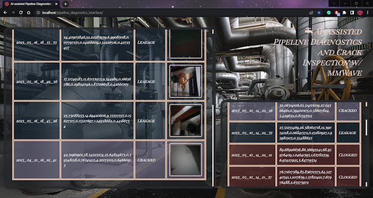
Then, I utilized the web application to obtain the model detection results with captured images of the deformed pipes from Nicla Vision via HTTP POST requests, save the received information to a particular MySQL database table, and display the stored model results with the assigned detection images on the application interface in descending order simultaneously.
Due to the fact that Nicla Vision can only generate raw image buffer (RGB565), this complementing web application executes a Python script to convert the received raw image buffer to a JPG file automatically before saving it to the server. After saving the converted image successfully, the web application adds it to the HTML table on the interface consecutively, allowing the user to inspect all previous model detection results and the assigned deformed pipe images in descending order.
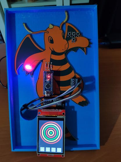
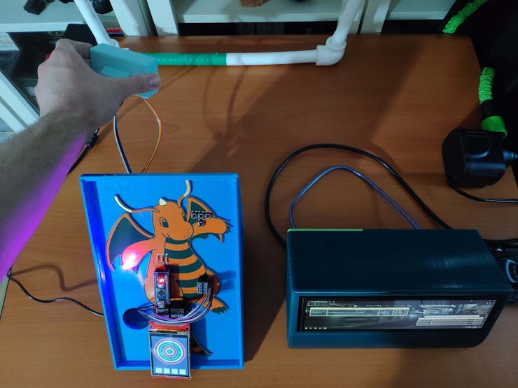
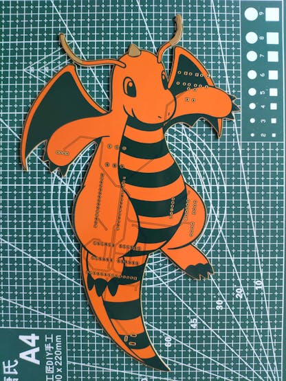
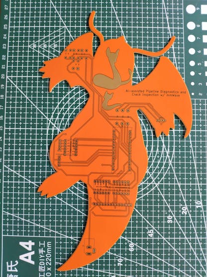
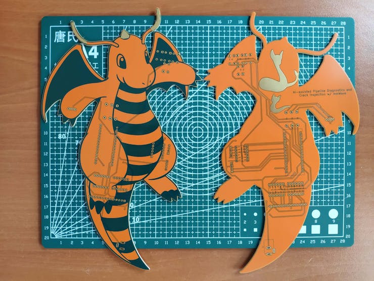
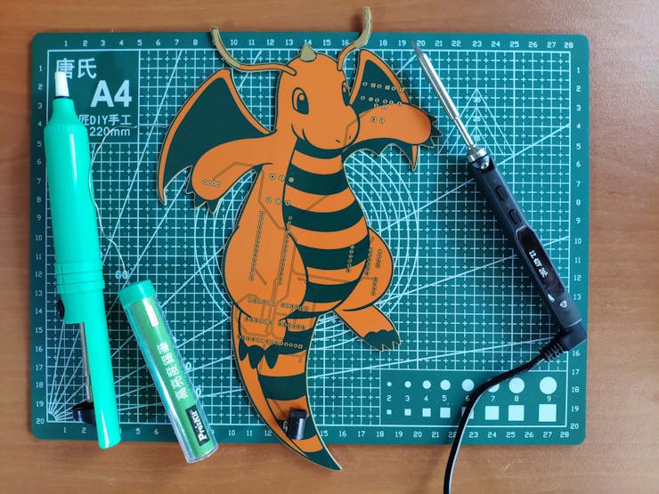
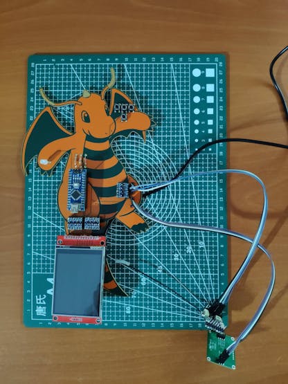
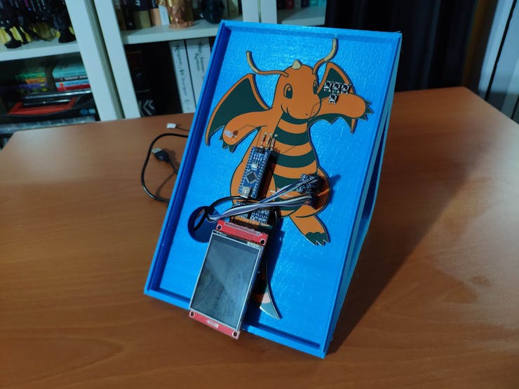
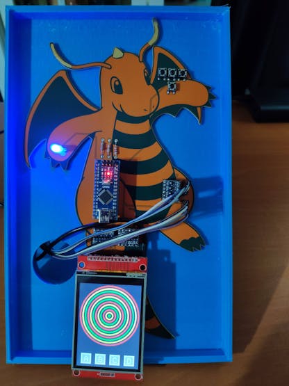
Considering harsh operating conditions, I decided to design a unique PCB after completing the wiring on a breadboard for the prototype and testing my code and neural network model. Since I wanted my PCB design to emanate a unique and powerful water-damage sensation, I decided to design a Dragonite-inspired PCB since it was the first scary water-related Pokémon for me from the anime, despite being a Dragon/Flying type Pokémon. Thanks to the unique orange solder mask and blue silkscreen combination, only provided by PCBWay, this PCB turned out to be my coolest design yet :)
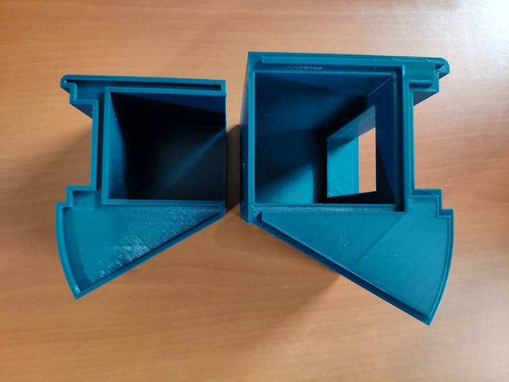
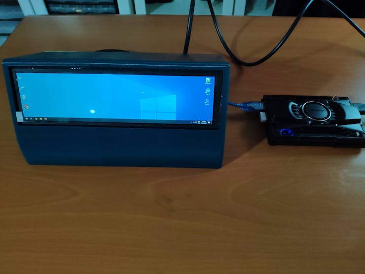
Since I decided to host my web application on LattePanda 3 Delta, I wanted to build a mobile and compact apparatus to display the web application in the field without requiring an additional procedure. To improve the user experience, I utilized a high-quality 8.8" IPS monitor from Elecrow. As explained in the following steps, I designed a two-part case (3D printable) in which I placed the Elecrow IPS monitor.
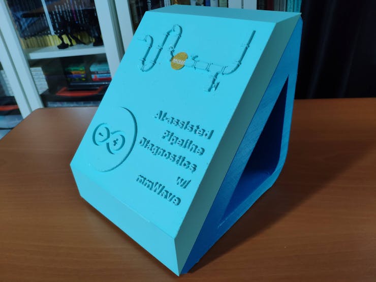
Lastly, to make the device as sturdy and compact as possible, I designed an emphasizing liquid-themed case with a sliding front cover and a modular camera holder providing a circular snap-fit joint (3D printable) for Nicla Vision and the 60GHz mmWave radar module.
So, this is my project in a nutshell 😃
In the following steps, you can find more detailed information on coding, capturing deformed pipe images, building a neural network model with Edge Impulse, running the model on Nicla Vision, and developing a full-fledged web application to obtain data parameters with captured images from Nicla Vision via HTTP POST requests.
🎁🎨 Huge thanks to PCBWay for sponsoring this project.
🎁🎨 Huge thanks to Elecrow for sending me an Elecrow 8.8" IPS Monitor (1920*480).
🎁🎨 Huge thanks to DFRobot for sending me a LattePanda 3 Delta 864
🎁🎨 Also, huge thanks to Anycubic for sponsoring a brand-new Anycubic Kobra 2.


Step 1: Designing and soldering the Dragonite-inspired PCB
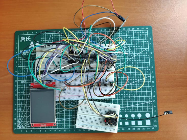
Before prototyping my Dragonite-inspired PCB design, I tested all connections and wiring with Nicla Vision and Arduino Nano. Then, I checked the data transfer processes between Nicla Vision and the web application hosted on LattePanda 3 Delta.

Then, I designed my Dragonite-inspired PCB by utilizing KiCad. As mentioned earlier, I wanted to design my PCB based on Dragonite since it was the first Pokémon that made me afraid of a water attack out of nowhere, despite being a Dragon/Flying type Pokémon :) Thanks to the unique orange solder mask and blue silkscreen combination, only provided by PCBWay, this PCB conveys a unique and effective water-damage sensation. I attached the Gerber file of the PCB below: You can order my design from PCBWay to build this device diagnosing pipeline system defects.
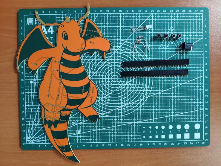
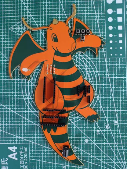
First of all, by utilizing a TS100 soldering iron, I attached headers (female), pushbuttons (6x6), resistors (220Ω), a 5mm common anode RGB LED, and a power jack to the PCB.
📌 Component list on the PCB:
A1 (Headers for Arduino Nano)
Nicla1 (Headers for Nicla Vision)
mmWave1 (Headers for 60GHz mmWave Module)
S1 (Headers for ILI9341 TFT LCD Screen)
L1, L2, L3 (Headers for Bi-Directional Logic Level Converter)
K1, K2, K3, K4 (6x6 Pushbutton)
D1 (5mm Common Anode RGB LED)
R1, R2, R3 (220Ω Resistor)
J1 (Power Jack)
Step 1.1: Making connections and adjustments
// Connections
// Arduino Nicla Vision :
//                                Arduino Nano
// UART_TX (PA_9)   --------------- A0
// UART_RX (PA_10)  --------------- A1
&
&
&
// Arduino Nano :
//                                Arduino Nicla Vision
// A0   --------------------------- UART_TX (PA_9)
// A1   --------------------------- UART_RX (PA_10)
//                                Seeed Studio 60GHz mmWave Sensor
// A2   --------------------------- TX
// A3   --------------------------- RX
//                                2.8'' 240x320 TFT LCD Touch Screen (ILI9341)
// D10  --------------------------- CS
// D9   --------------------------- RESET
// D8   --------------------------- D/C
// D11  --------------------------- SDI (MOSI)
// D13  --------------------------- SCK
// 3.3V --------------------------- LED
// D12  --------------------------- SDO(MISO)
//                                Control Button (A)
// D2   --------------------------- +
//                                Control Button (B)
// D4   --------------------------- +
//                                Control Button (C)
// D7   --------------------------- +
//                                Control Button (D)
// A4   --------------------------- +
//                                5mm Common Anode RGB LED
// D3   --------------------------- R
// D5   --------------------------- G
// D6   --------------------------- B
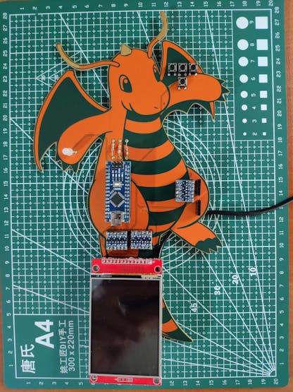
After completing soldering, I attached all remaining components to the Dragonite PCB via headers — Nicla Vision, Arduino Nano, 60GHz mmWave radar module, bi-directional logic level converters, and ILI9341 TFT LCD screen.
Due to architecture and library incompatibilities, I decided to connect the mmWave module and the ILI9341 TFT LCD screen to Arduino Nano so as to extract and display data parameters. Then, I utilized Arduino Nano to transmit the collected mmWave data parameters and user commands to Nicla Vision via serial communication.
Since Arduino Nano operates at 5V and Nicla Vision requires 3.3V logic level voltage, they cannot be connected with each other directly. Therefore, I utilized a bi-directional logic level converter to shift the voltage for the connections between Nicla Vision and Arduino Nano.
Even though the ILI9341 TFT screen can be supplied with 5V, it generates 3.3V interface voltage. Therefore, connecting its SPI pins to a 5V board like Arduino Nano leads to black screen and freezing issues. To make the ILI9341 screen stable, I utilized two bi-directional logic level converters shifting the voltage for the connections between the ILI9341 screen and Arduino Nano.
To be able to transfer commands to Nicla Vision via serial communication, I connected the software serial port of Arduino Nano (Nicla) to the hardware serial port of Nicla Vision (Serial1). To communicate with the MR60BHA1 60GHz radar module, I connected the software serial port of Arduino Nano (mmWave) to the module's built-in UART interface.
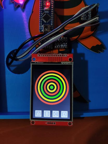
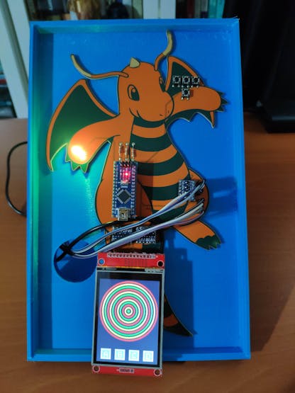
I utilized the ILI9341 TFT screen to display ongoing operations and visualize the extracted mmWave data parameters by creating a simple radar indicator. Then, I added four control buttons to transfer the collected data parameters and user commands to Nicla Vision via serial communication. Also, I added an RGB LED to inform the user of the device status, denoting serial communication and data collection success.
Step 2: Designing and printing a liquid-themed case w/ Anycubic Kobra 2
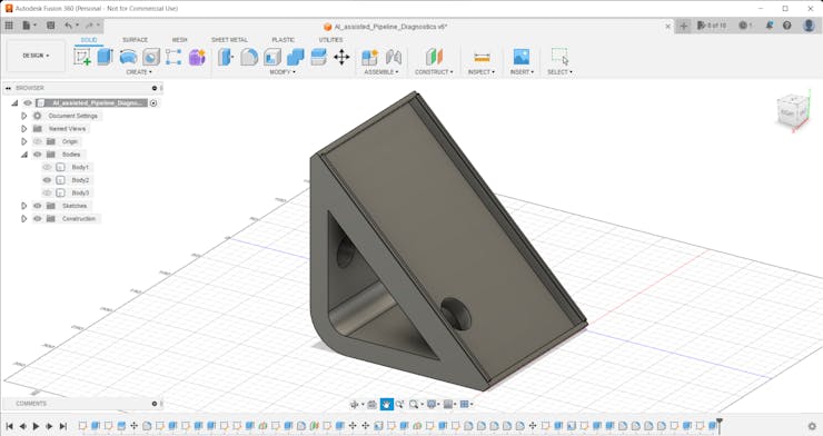
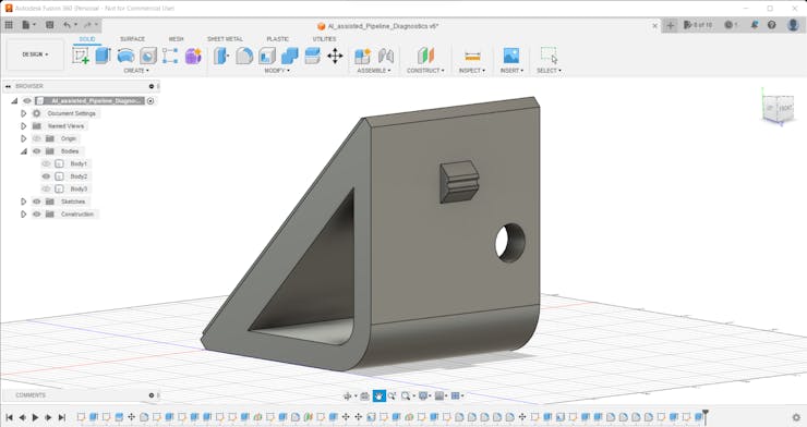
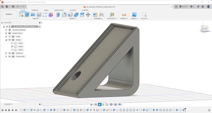
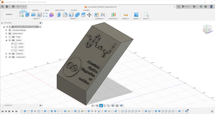
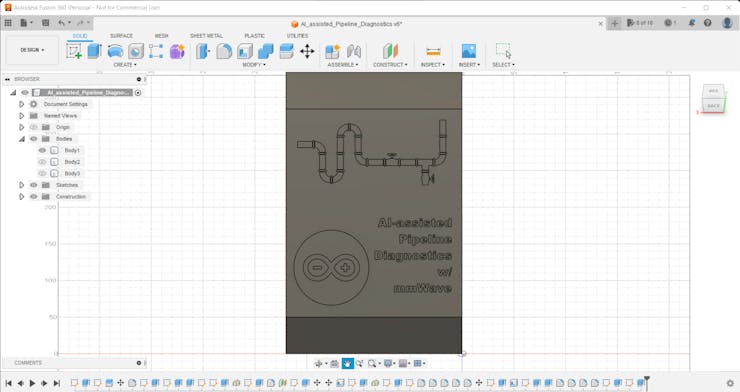
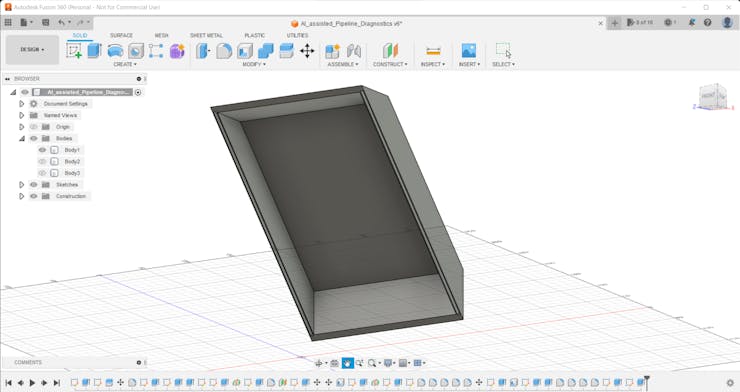
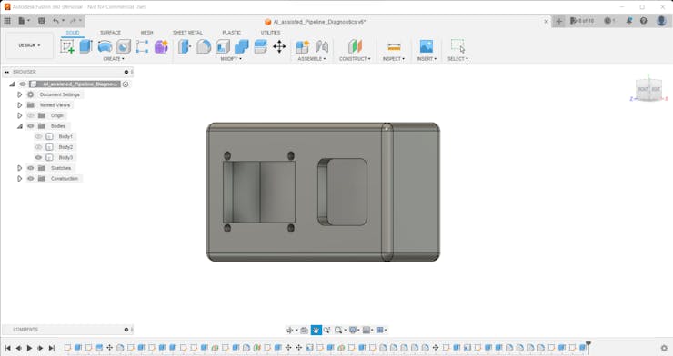
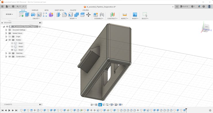
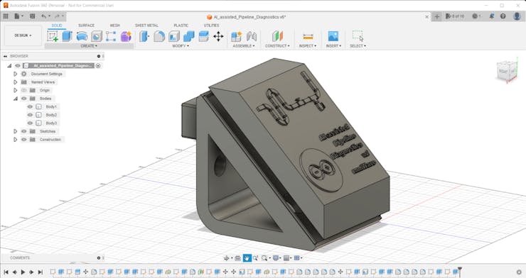
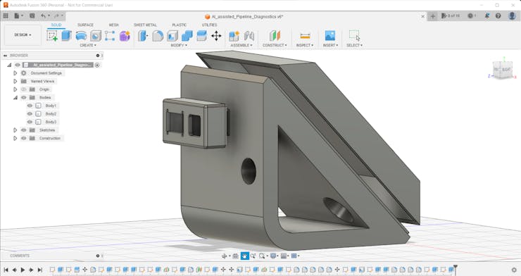
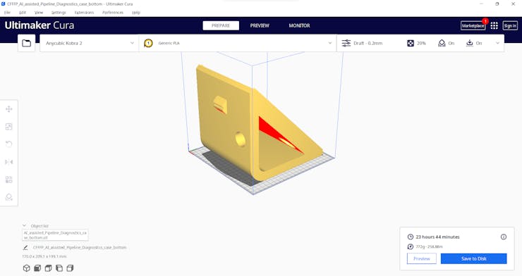
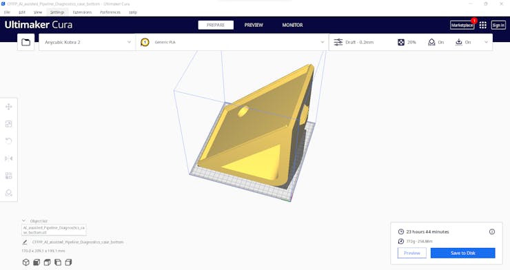
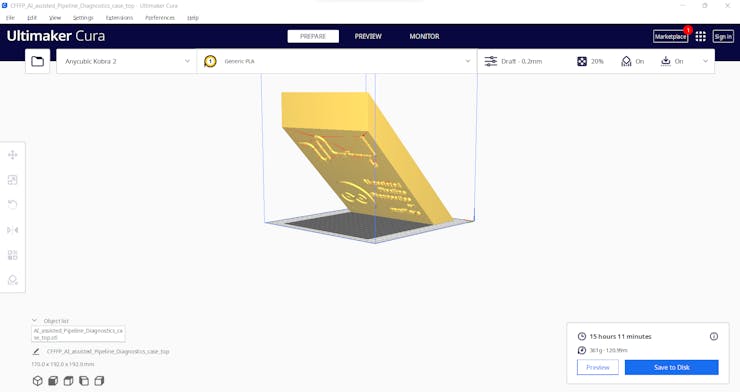
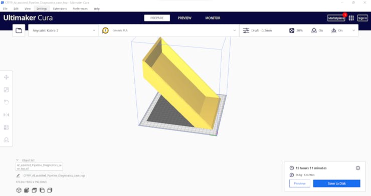
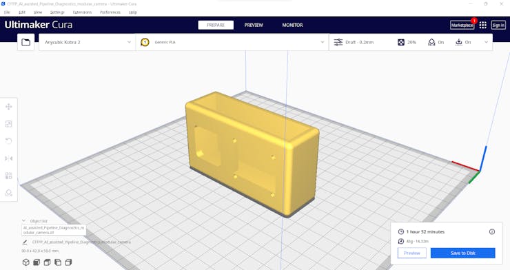
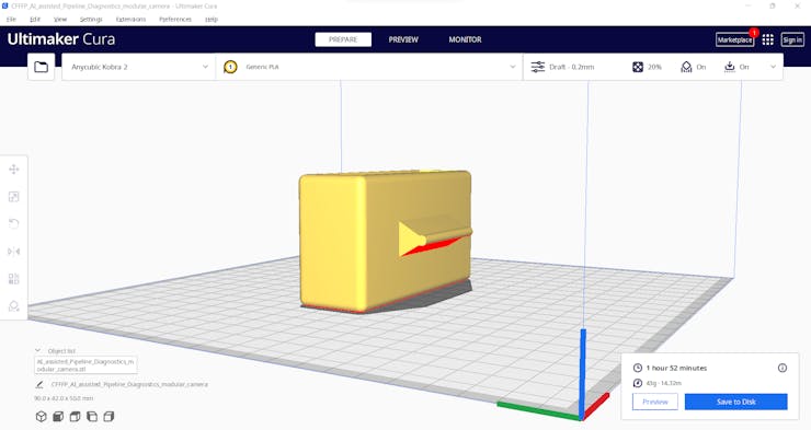
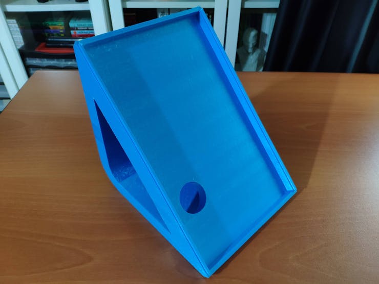
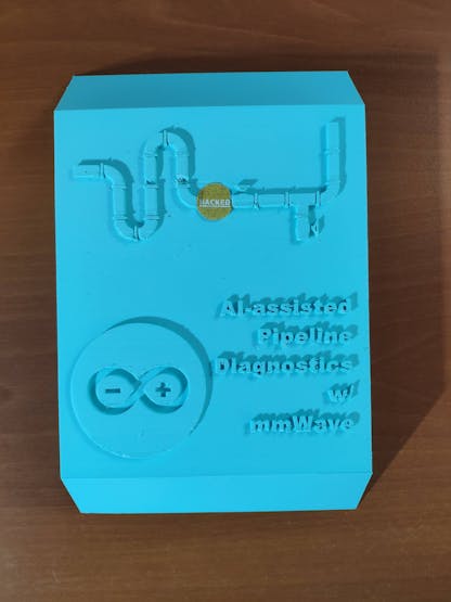
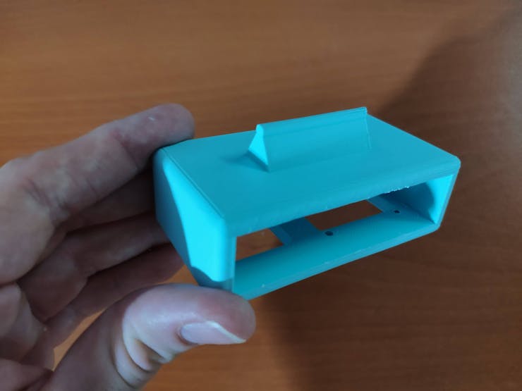
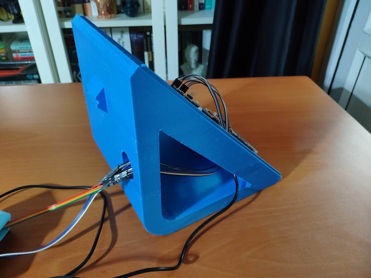
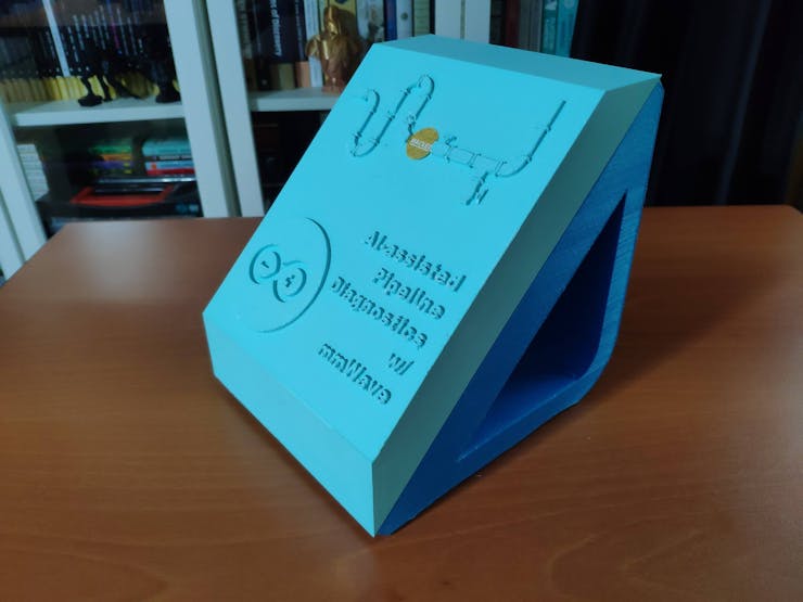
Since I focused on building a user-friendly and accessible mechanism that collects mmWave data parameters and runs a neural network model to inform the user of the diagnosed pipeline defects via a PHP web application, I decided to design a rigid and compact case allowing the user to place the 60GHz mmWave module and position the built-in GC2145 camera on Nicla Vision effortlessly. To avoid overexposure to dust and prevent loose wire connections, I added a sliding front cover aligned proportionally to the diagonal top surface. Then, I designed a modular camera holder mountable to the back of the case via a circular snap-fit joint. Also, I decided to emboss pipe icons and the Arduino symbol on the sliding front cover to emphasize the edge pipeline diagnostic processes.
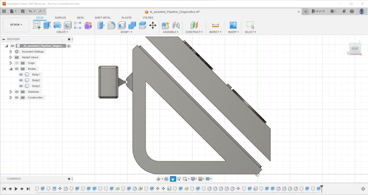
Since I needed to attach the Dragonite PCB to the main case, I decided to design an oblique structure for the case. In that regard, I was able to fit the PCB in the case without enlarging the case dimensions.
I designed the main case, its sliding front cover, and the modular camera holder in Autodesk Fusion 360. You can download their STL files below.
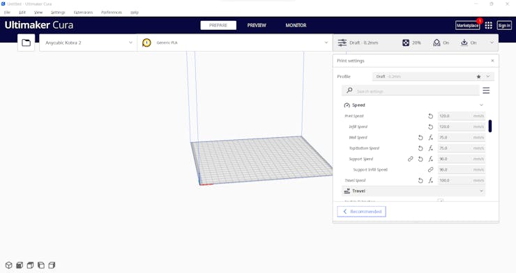
Then, I sliced all 3D models (STL files) in Ultimaker Cura.
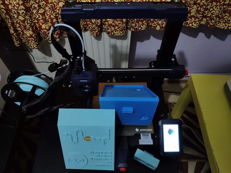
Since I wanted to create a shiny structure for the main case and apply a unique liquid theme indicating water damage, I utilized these PLA filaments:
- eSilk Cyan
- ePLA-Matte Light Blue
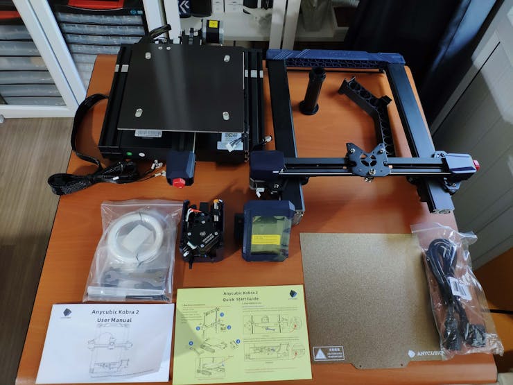
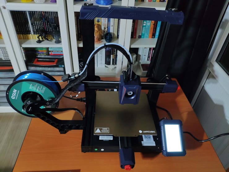
Finally, I printed all parts (models) with my brand-new Anycubic Kobra 2 3D Printer.
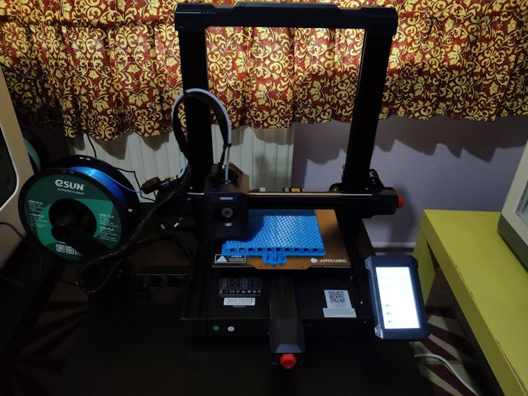
Since Anycubic Kobra 2 is budget-friendly and specifically designed for high-speed printing, I highly recommend Anycubic Kobra 2 if you are a maker or hobbyist needing to print multiple prototypes before finalizing a complex project.
Thanks to its upgraded direct extruder, Anycubic Kobra 2 provides 150mm/s recommended print speed (up to 250mm/s) and dual-gear filament feeding. Also, it provides a cooling fan with an optimized dissipation design to support rapid cooling complementing the fast printing experience. Since the Z-axis has a double-threaded rod structure, it flattens the building platform and reduces the printing layers, even at a higher speed.
Furthermore, Anycubic Kobra 2 provides a magnetic suction platform on the heated bed for the scratch-resistant spring steel build plate allowing the user to remove prints without any struggle. Most importantly, you can level the bed automatically via its user-friendly LeviQ 2.0 automatic bed leveling system. Also, it has a smart filament runout sensor and the resume printing function for power failures.
#️⃣ First of all, install the gantry and the spring steel build plate.
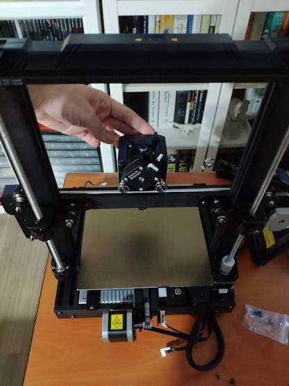
#️⃣ Install the print head, the touch screen, and the filament runout sensor.
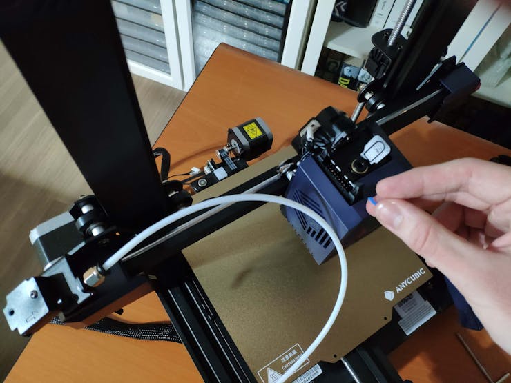

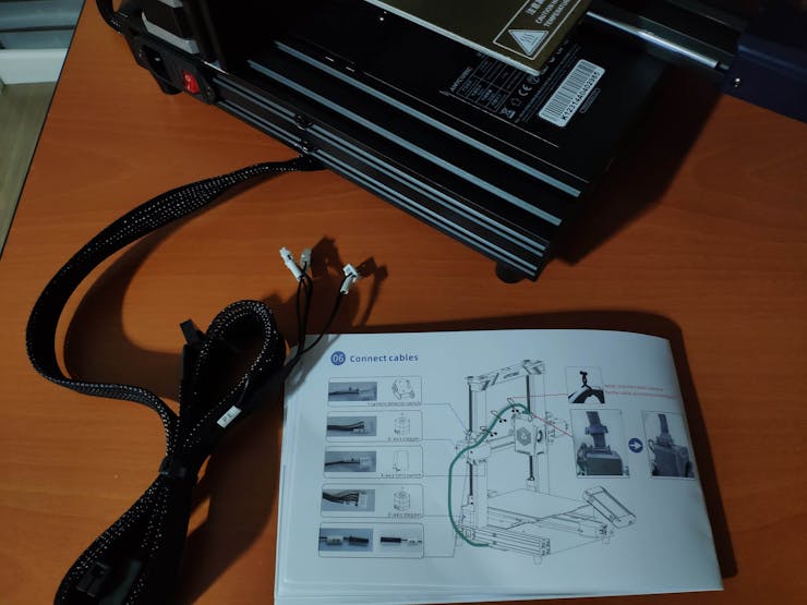
#️⃣ Connect the stepper, switch, screen, and print head cables. Then, attach the filament tube.
#️⃣ If the print head is shaking, adjust the hexagonal isolation column under the print head.
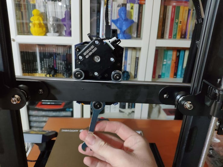
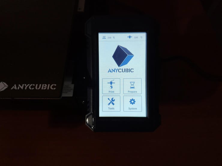
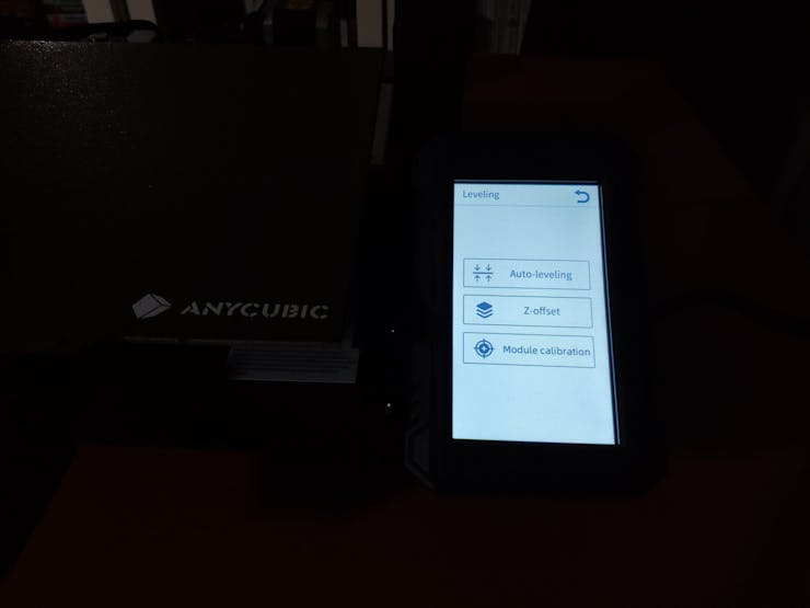
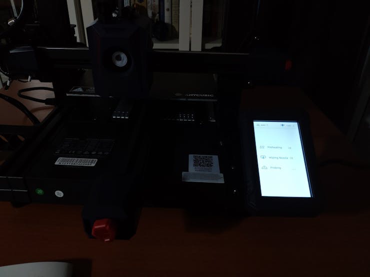
#️⃣ Go to Prepare➡ Leveling ➡ Auto-leveling to initiate the LeviQ 2.0 automatic bed leveling system.
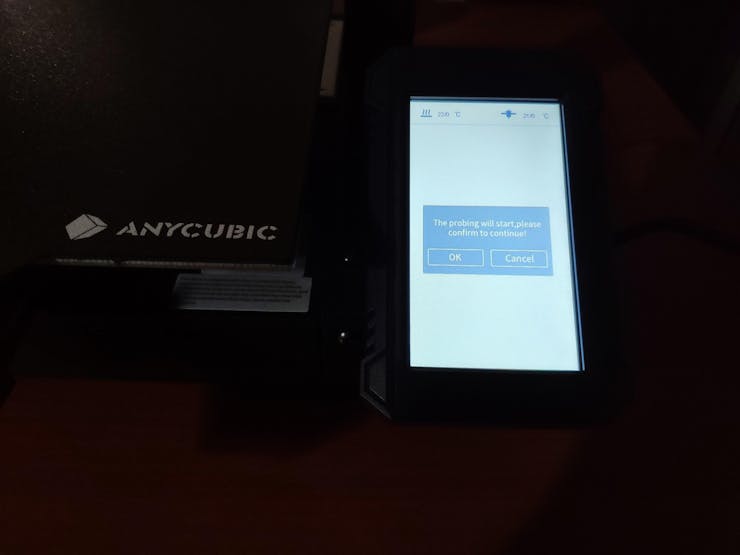
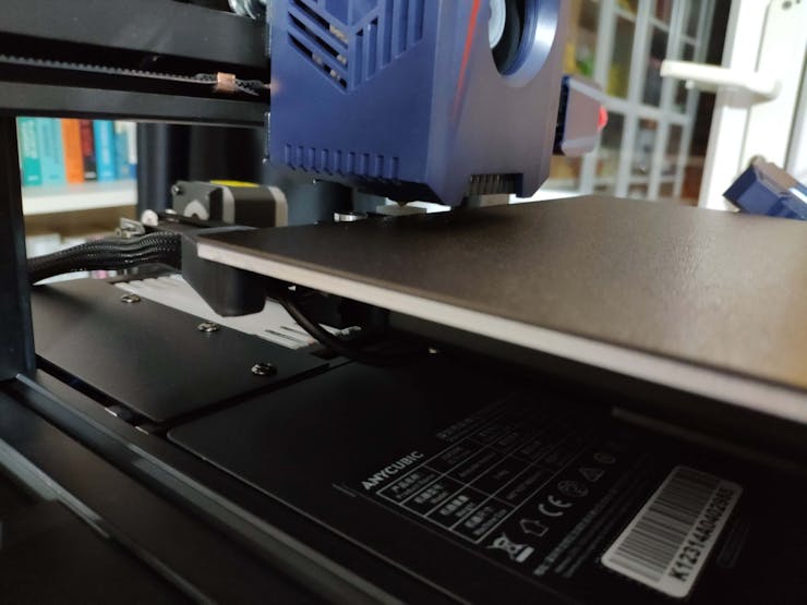
#️⃣ After preheating and wiping the nozzle, Anycubic Kobra 2 probes the predefined points to level the bed.
#️⃣ Finally, fix the filament tube with the cable clips, install the filament holder, and insert the filament into the extruder.
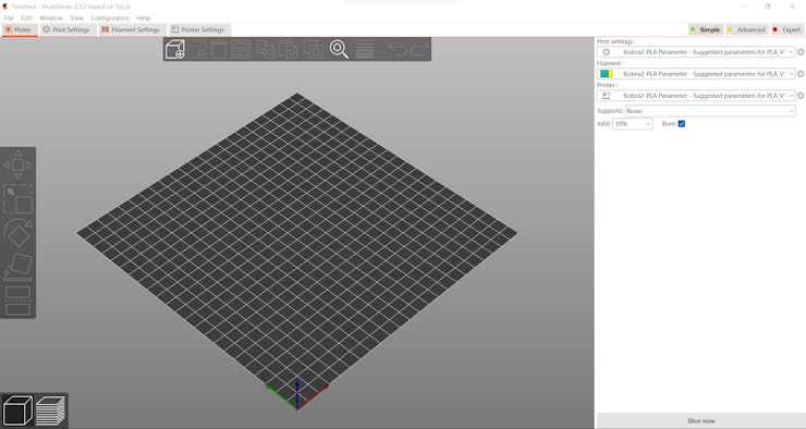
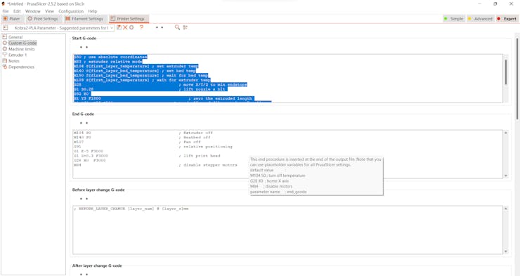
#️⃣ Since Anycubic Kobra 2 is not officially supported by Cura yet, download the latest PrusaSlicer version and import the printer profile (configuration) file provided by Anycubic.
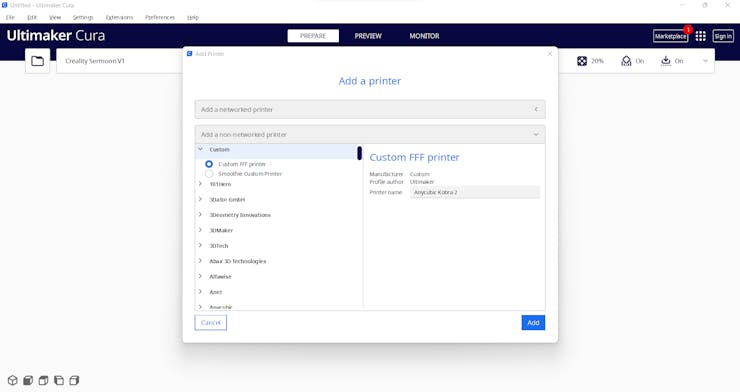
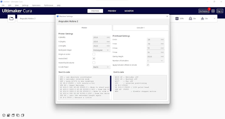
#️⃣ Then, create a custom printer profile on Cura for Anycubic Kobra 2 and change Start G-code and End G-code.
#️⃣ Based on the provided Start G-code and End G-code in the configuration file, I modified new Start G-code and End G-code compatible with Cura.
Start G-code:

G90 ; use absolute coordinates
M83 ; extruder relative mode
G28 ; move X/Y/Z to min endstops
G1 Z2.0 F3000 ; lift nozzle a bit
G92 E0 ; Reset Extruder
G1 X10.1 Y20 Z0.28 F5000.0 ; Move to start position
G1 X10.1 Y200.0 Z0.28 F1500.0 E15 ; Draw the first line
G1 X10.4 Y200.0 Z0.28 F5000.0 ; Move to side a little
G1 X10.4 Y20 Z0.28 F1500.0 E30 ; Draw the second line
G92 E0 ; zero the extruded length again
G1 E-2 F500 ; Retract a little
M117
G21 ; set units to millimeters
G90 ; use absolute coordinates
M82 ; use absolute distances for extrusion
G92 E0M107

End G-code:


M104
S0 ; Extruder off
M140 S0 ; Heatbed off
M107    ; Fan off
G91     ; relative positioning
G1 E-5 F3000
G1 Z+0.3 F3000 ; lift print head
G28 X0  F3000
M84            ; disable stepper motors
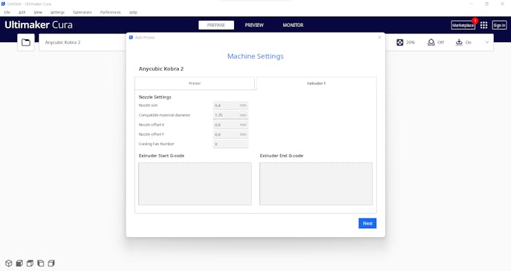
#️⃣ Finally, adjust the official printer settings depending on the filament type while copying them from PrusaSlicer to Cura.

Step 2.1: Assembling the liquid-themed case
After printing all parts (models), I fastened Dragonite PCB to the diagonal top surface of the main case via a hot glue gun.
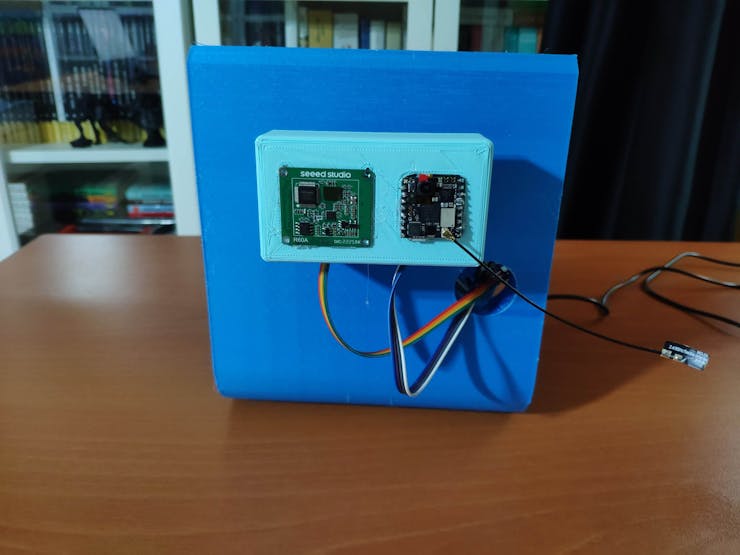
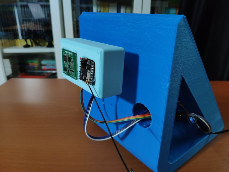
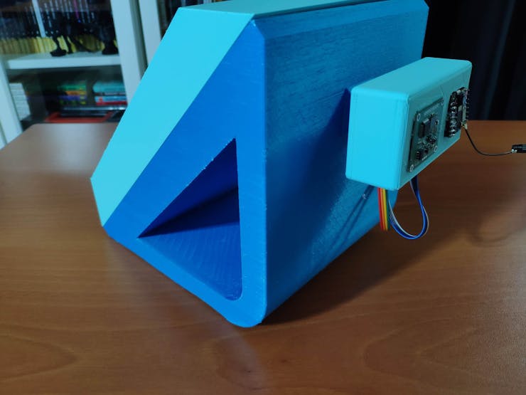
I placed Nicla Vision and the 60GHz mmWave module in the modular camera holder. Then, I attached the camera holder to the main case via its circular snap-fit joint.
Finally, I inserted the sliding front cover via the dents on the diagonal top surface of the main case.
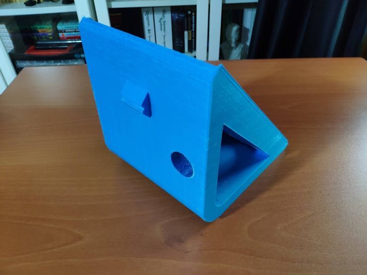
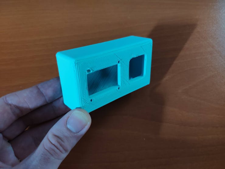
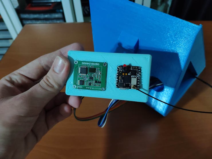
As mentioned earlier, the modular camera holder can be utilized to place the 60GHz mmWave module and position the built-in GC2145 camera on Nicla Vision.
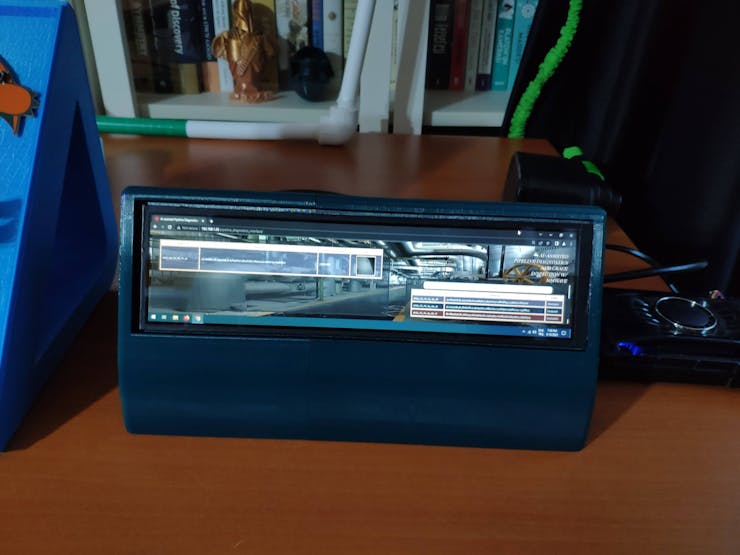
Step 2.2: Creating a LattePanda Deck to display the web application
Since I decided to utilize the web application to display the collected data parameters, generate the pre-formatted CSV file from the stored data records in the database, and show the model detection results with the captured images of the deformed pipes, I wanted to create a unique apparatus to inspect the web application.
Since I host this web application on my LattePanda 3 Delta, I decided to design a unique and compact LattePanda Deck compatible with not only LattePanda but also any single-board computer supporting HDMI.
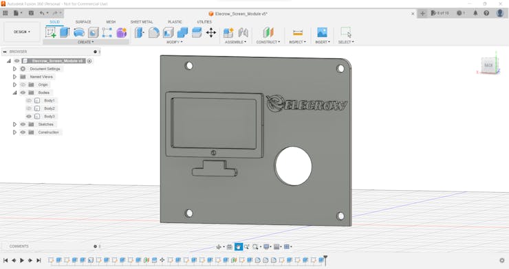
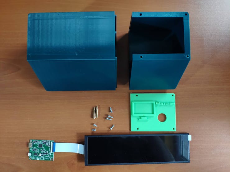
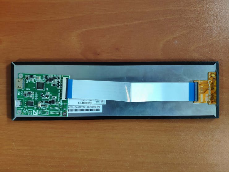
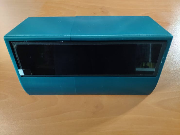
I decided to employ Elecrow's 8.8" (1920*480) high-resolution IPS monitor as the screen of my LattePanda Deck. Thanks to its converter board, this monitor can be powered via a USB port and works without installing any drivers. Therefore, it is a compact plug-and-play monitor for LattePanda 3 Delta, providing high resolution and up to 60Hz refresh rate.
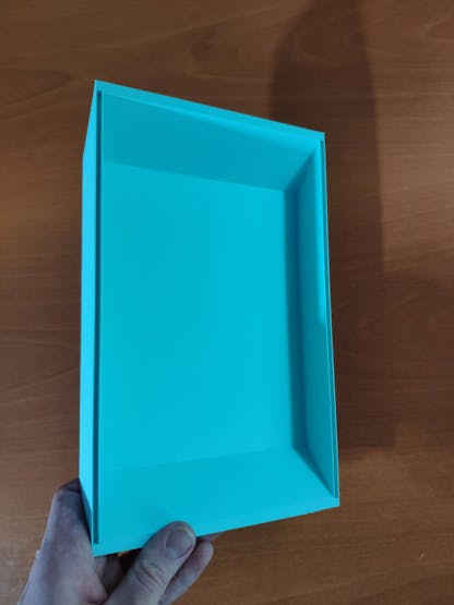
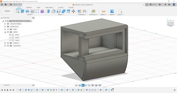
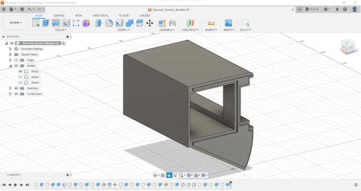
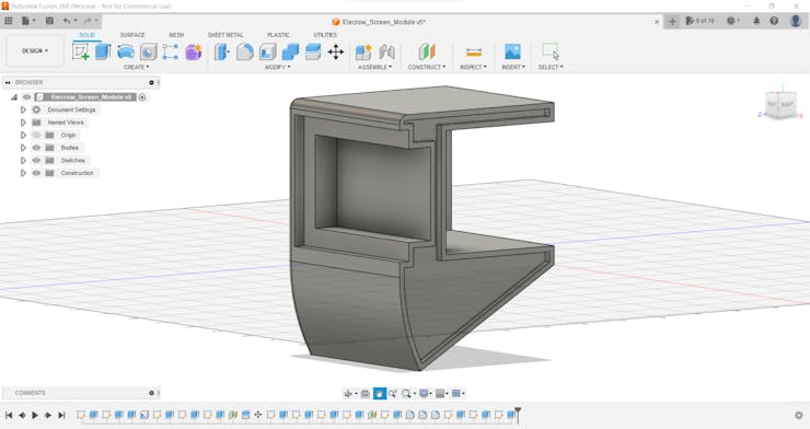
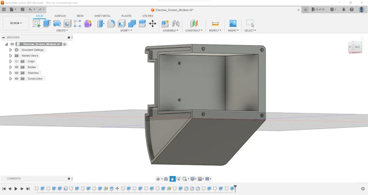
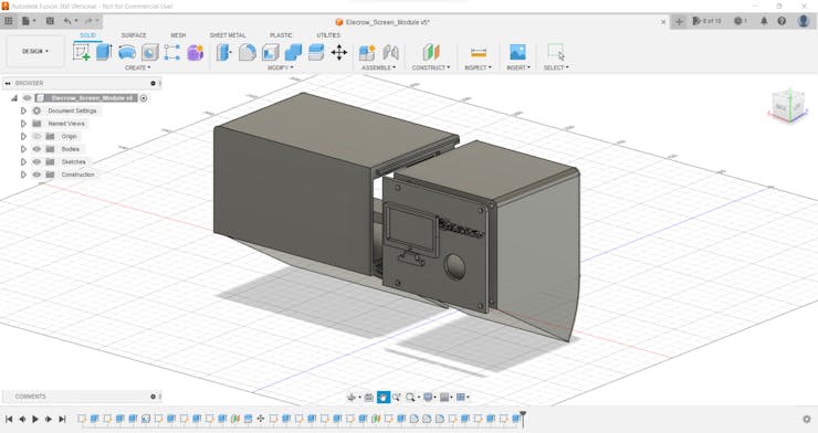
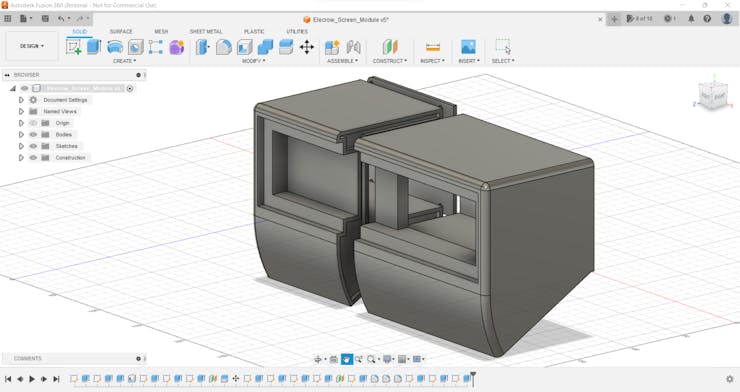
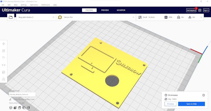
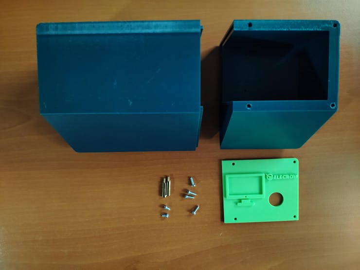
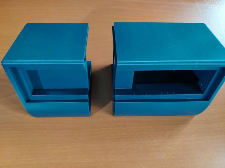
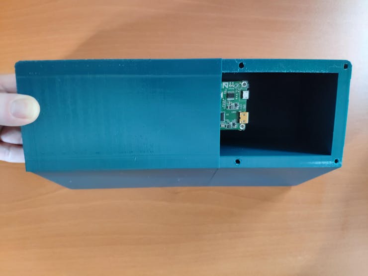
Due to the fact that I wanted to build a sturdy and easy-to-use deck, I designed a two-part case covering the screen frame and providing a slot for the converter board. To avoid overexposure to dust and provide room for cable management, I added a mountable back cover adorned with the brand logo.
I designed the two-part case and its mountable back cover in Autodesk Fusion 360. You can download their STL files below.
Then, I sliced all 3D models (STL files) in Ultimaker Cura.
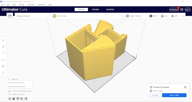
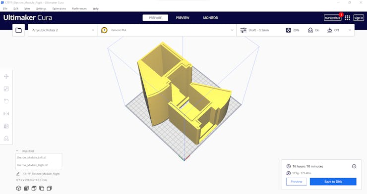
After printing all deck parts (models) with my Anycubic Kobra 2 3D Printer, I affixed the two-part case together via the hot glue gun.
Then, I fastened the Elecrow's IPS monitor to the case covering the screen frame and inserted the converter board into its slot.
After attaching the required cables to the converter board, I fixed the mountable back cover via M3 screws.
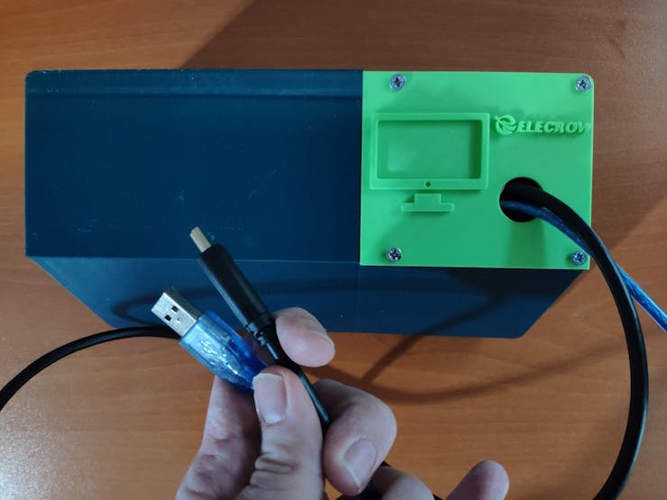
After connecting the converter board to LattePanda 3 Delta via its USB and HDMI ports, LattePanda recognizes the IPS monitor automatically.
Step 3: Developing a web application displaying real-time database updates in PHP, JavaScript, CSS, and MySQL
Step 4: Setting up Nicla Vision on Arduino IDE
Step 5.0: Building a basic pipeline system demonstrating different defects
Step 5: Collecting mmWave data parameters and communicating with Nicla Vision via serial communication w/ Arduino Nano
Step 5.1: Storing and converting the collected data parameters to samples via the web application
After uploading and running the code for collecting mmWave data parameters and transferring the collected data with the selected class to Nicla Vision via serial communication:
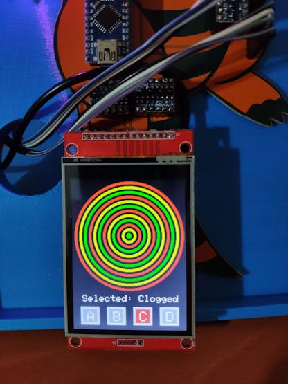
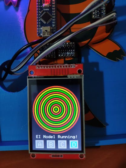
🚿🔎📲 If the 60GHz mmWave radar module works accurately, the device turns the RGB LED to magenta and displays the simple radar indicator visualizing the extracted mmWave data parameters and the interface menu buttons on the ILI9341 TFT LCD screen.

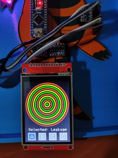
🚿🔎📲 If the control button (A) is pressed, Arduino Nano adds Leakage as the selected pipeline diagnostic class to the recently extracted mmWave data parameters, transfers the modified data record to Nicla Vision via serial communication, and turns the RGB LED to blue.
🚿🔎📲 Then, it switches the interface button (A) color to blue and shows the simple radar indicator visualizing the extracted mmWave data parameters on the ILI9341 TFT LCD screen.
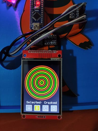
🚿🔎📲 If the control button (B) is pressed, Arduino Nano adds Cracked as the selected pipeline diagnostic class to the recently extracted mmWave data parameters, transfers the modified data record to Nicla Vision via serial communication, and turns the RGB LED to yellow.
🚿🔎📲 Then, it switches the interface button (B) color to yellow and shows the simple radar indicator visualizing the extracted mmWave data parameters on the ILI9341 TFT LCD screen.
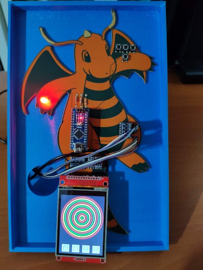
🚿🔎📲 If the control button (C) is pressed, Arduino Nano adds Clogged as the selected pipeline diagnostic class to the recently extracted mmWave data parameters, transfers the modified data record to Nicla Vision via serial communication, and turns the RGB LED to red.
🚿🔎📲 Then, it switches the interface button (C) color to red and shows the simple radar indicator visualizing the extracted mmWave data parameters on the ILI9341 TFT LCD screen.

🚿🔎📲 After pressing the control buttons (A, B, or C), Arduino Nano sends the Data command to Nicla Vision via serial communication. When Nicla Vision receives the Data command, it transmits the received mmWave data parameters and selected pipeline diagnostic class to the web application via an HTTP GET request.
🚿🔎📲 Also, Arduino Nano prints notifications and sensor measurements on the serial monitor for debugging.

After collecting mmWave data parameters (vibration fluctuations) from my pipeline system that manifests three different pipeline defects and creating the pre-formatted CSV file consisting of the stored data records as samples via the web application, I elicited my data set with eminent validity and veracity.