 Kevin Santo Cappuccio
I'm going to do a high-level explanation of what the code in the Jumperless is actually doing. There's a lot going on and it's in a bunch of separate files so I think it will be helpful for people who what to understand or improve upon it.
Table of Contents (bolded ones are in this project log)
- General terms - the names I've decided to call things
- What's being stored - how the overall state is stored
- File Parsing - how we fill in those arrays
- Pathfinding - how we find valid paths for each connection
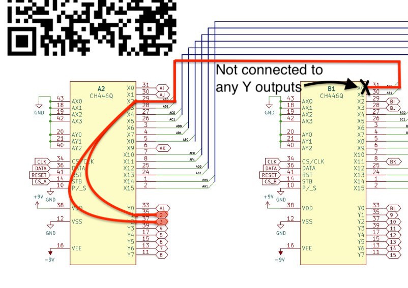
- Controlling the crosspoint switches - how we send that data to the CH446Qs
- LEDs - how we choose unique colors for each net
- The Wokwi bridge app - how we scrape the Wokwi page for updates
This is going to be really long and so I'll be filling out parts as I finish them in no particular order.
General terms
I've made up terms for things here that may or may not be the formal definition, so I should probably let you know what I chose.
Breadboard Chips - This refers to the 8 CH446Q crosspoint switches (labeled A-H) that have their Y pins connected to the breadboard. This excludes Chip L which actually has it's X pins connected to the 4 corners of the board (rows 1, 30, 31 (b1), 60 (b30))
Special Function Chips - This refers to the 4 crosspoints (labeled I-L) that connect to everything else; the Nano header, power supplies, DACs, GPIO from the RP2040, etc...

Nodes - Also used synonymously with Row especially when it's on the breadboard or Nano Header. And end point to a bridge
Bridges - Just 2 nodes that should be connected
Nets - Groups of nodes and bridges that should all be electrically connected to each other
Bounce - Sometimes there won't be an available path directly from one node to another, so in this case it will pick another chip with a free path to the start and end chips and "bounce" through it.
Paths - Similar to a bridge, except that it contains data for how that bridge is connected. So it will have which chips and which X and X pins are needed to make the connection
Defines
You'll see a lot of these, they're all in JumperlessDefinesRP2040.h. But the point of this whole this is so you don't have to dig through the code, so I'll put the abridged version here:
#define CHIP_A 0
...
#define CHIP_L 11


#define t1  1
...
#define t30 30

#define b1  31
...
#define b30 60


#define NANO_D0  70 //these are completely arbitrary
...
#define NANO_A7  93


#define GND  100 #define SUPPLY_3V3  103
#define SUPPLY_5V  105

#define DAC0_5V  106 #define DAC1_8V  107

#define CURRENT_SENSE_PLUS  108
#define CURRENT_SENSE_MINUS  109

#define ADC0_5V 110
#define ADC1_5V 111
#define ADC2_5V 112
#define ADC3_8V 113

#define EMPTY_NET 127
What's being stored
There are a few big arrays of structs that store the overall state of everything. Here are the main ones:
chipStatus
This stores the actual hardware layout of each of the 12 crosspoint switches, like what is physically connected where and whether that path is being used. In the code it's and array called ch[12] and it's in MatrixStateRP2040.h
//the struct
struct chipStatus{
int chipNumber;
char chipChar;
int8_t xStatus[16]; //store the bb row or nano conn this is eventually connected to so they can be stacked if conns are redundant
int8_t yStatus[8];  //store the row/nano it's connected to
const int8_t xMap[16];
const int8_t yMap[8];
};

//the array of those structs
struct chipStatus ch[12] = {  {0,'A',  {-1,-1,-1,-1,-1,-1,-1,-1,-1,-1,-1,-1,-1,-1,-1,-1}, // x status  {-1,-1,-1,-1,-1,-1,-1,-1}, //y status  {CHIP_I, CHIP_J, CHIP_B, CHIP_B, CHIP_C, CHIP_C, CHIP_D, CHIP_D, CHIP_E, CHIP_K, CHIP_F, CHIP_F, CHIP_G, CHIP_G, CHIP_H, CHIP_H},//X MAP constant  {CHIP_L,  t2,t3, t4, t5, t6, t7, t8}},  // Y MAP constant
...  {10,'K',  {-1,-1,-1,-1,-1,-1,-1,-1,-1,-1,-1,-1,-1,-1,-1,-1}, // x status  {-1,-1,-1,-1,-1,-1,-1,-1}, //y status  {NANO_A0, NANO_A1, NANO_A2, NANO_A3, NANO_D2, NANO_D3, NANO_D4, NANO_D5, NANO_D6, NANO_D7, NANO_D8, NANO_D9, NANO_D10, NANO_D11, NANO_D12, ADC2_5V},  {CHIP_A,CHIP_B,CHIP_C,CHIP_D,CHIP_E,CHIP_F,CHIP_G,CHIP_H}},
  {11,'L',  {-1,-1,-1,-1,-1,-1,-1,-1,-1,-1,-1,-1,-1,-1,-1,-1}, // x status  {-1,-1,-1,-1,-1,-1,-1,-1}, //y status  {CURRENT_SENSE_MINUS, CURRENT_SENSE_PLUS, ADC0_5V, ADC1_5V, ADC2_5V, ADC3_8V, DAC1_8V, DAC0_5V, t1, t30, b1, b30, NANO_A4, NANO_A5, SUPPLY_5V, GND},  {CHIP_A,CHIP_B,CHIP_C,CHIP_D,CHIP_E,CHIP_F,CHIP_G,CHIP_H}}  };
In general, I use -1 to mean the path is availale to be connected to something. As the pathfinding algorithm runs, it will fill up xStatus and yStatus with the net they're connected to.
Paths
Each path is also stored as an array of structs, this also gets filled out as the pathfinding stuff runs. There are also a couple enums to store the type of path it is, which becomes important for pathfinding because they all are sort of dealt with differently. Note that chip L is kind of a special case because it's kind of the special function chip among special function chips. Most notably, it's Y pins are actually connected to the Y pins on the breadboard chips instead of the X pins like the rest of the special function chips.
enum pathType {BBtoBB, BBtoNANO, NANOtoNANO, BBtoSF, NANOtoSF, BBtoBBL, NANOtoBBL, SFtoSF, SFtoBBL, BBLtoBBL};

enum nodeType {BB, NANO, SF, BBL};

struct pathStruct{
  int node1; //these are the rows or nano header pins to connect  int node2;  int net;   int chip[4];  int x[6];  int y[6];  int candidates[3][3]; //[node][candidate]  int altPathNeeded;  enum pathType pathType;  enum nodeType nodeType[3];  bool sameChip;  bool Lchip;

};

extern struct pathStruct path[MAX_BRIDGES]; //this is the array of paths
Nets
This is where it stores all the info about the nets, this is filled in early on in this whole process during input parsing.
struct netStruct{ uint8_t number;                  //nets are uint8_t, nodes are int8_t
const char *name;                // human readable "Net 3"
int8_t nodes[MAX_NODES] = {};    //maybe make this smaller and allow nets to just stay connected currently 64x64 is 4 Kb
int8_t bridges[MAX_NODES][2];    //either store them here or in one long array that references the net
int8_t specialFunction = -1;     // store #defined number for that special function -1 for regular net
uint8_t intersections[8];        //if this net shares a node with another net, store this here. If it's a regular net, we'll need a function to just merge them into one new net. special functions can intersect though (except Power and Ground), 0x7f is a reserved empty net that nothing and intersect
int8_t doNotIntersectNodes[8];   //if the net tries to share a node with a net that contains any #defined nodes here, it won't connect and throw an error (SUPPLY to GND)
rgbColor color;                  //color of the net in hex
};

extern struct netStruct net[MAX_NETS];

//The first 8 nets are the Special Function Nets so they're always filled

struct netStruct net[MAX_NETS] = { //these are the special function nets that will always be made
//netNumber,       ,netName          ,memberNodes[]         ,memberBridges[][2]     ,specialFunction        ,intsctNet[] ,doNotIntersectNodes[]                 ,priority    {     127      ,"Empty Net"      ,{EMPTY_NET}           ,{{}}                   ,EMPTY_NET              ,{}          ,{EMPTY_NET,EMPTY_NET,EMPTY_NET,EMPTY_NET,EMPTY_NET,EMPTY_NET,EMPTY_NET} , 0},         {     1        ,"GND\t"          ,{GND}                 ,{{}}                   ,GND                    ,{}          ,{SUPPLY_3V3,SUPPLY_5V,DAC0_5V,DAC1_8V}    , 1},    {     2        ,"+5V\t"          ,{SUPPLY_5V}           ,{{}}                   ,SUPPLY_5V              ,{}          ,{GND,SUPPLY_3V3,DAC0_5V,DAC1_8V}          , 1},    {     3        ,"+3.3V\t"        ,{SUPPLY_3V3}          ,{{}}                   ,SUPPLY_3V3             ,{}          ,{GND,SUPPLY_5V,DAC0_5V,DAC1_8V}           , 1},    {     4        ,"DAC 0\t"        ,{DAC0_5V}             ,{{}}                   ,DAC0_5V                ,{}          ,{GND,SUPPLY_5V,SUPPLY_3V3,DAC1_8V}        , 1},    {     5        ,"DAC 1\t"        ,{DAC1_8V}             ,{{}}                   ,DAC1_8V                ,{}          ,{GND,SUPPLY_5V,SUPPLY_3V3,DAC0_5V}        , 1},    {     6        ,"I Sense +"      ,{CURRENT_SENSE_PLUS}  ,{{}}                   ,CURRENT_SENSE_PLUS     ,{}          ,{CURRENT_SENSE_MINUS}                     , 2},    {     7        ,"I Sense -"      ,{CURRENT_SENSE_MINUS} ,{{}}                   ,CURRENT_SENSE_MINUS    ,{}          ,{CURRENT_SENSE_PLUS}                      , 2},
};

char *netNameConstants[MAX_NETS] = {(char*)"Net 0",(char*)"Net 1",(char*)"Net 2" ... (char*)"Net 62"}; //Thanks Copilot
Cool, so those 3 arrays are basically the important ones you'll need to be aware of when I go through the rest of how this all works
File Parsing
I guess "file" is a bit of a misnomer here, the main way of using this thing right now is via the JumperlessWokwiBridge app and that just sends data over serial where it's directly stored into the Nets array. There is support for loading a file using LittleFS but that's not the main way I use this thing anymore because it's slower. But the format is exactly the same.
There are actually 2 indentical file parsers, one in the Wokwi Bridge app and another on the Jumperless, they do the same thing. Really all they do is go through the list formatted with human readable names and replace them with the #defined numbers above. So D0 is replaced with 70 and DAC1_8V is replaced with 107.
Extra formatting is an "opening curly brace" "newline", then "dashes" between nodes and "comma newline" between bridges.
{
45-GND,
15-SUPPLY_5V,
23-16,
17-46,
42-47,
51-23,
53-52,
48-SUPPLY_3V,
59-46,
DAC1_8V-57,
17-2,
DAC0_5V-26,
ADC3_8V-57,
29-SUPPLY_5V,
GND-34,
A3-D10,
A2-12,
A0-10,
35-SUPPLY_3V,
11-D8,
A5-20,
9-8,
}
Gets parsed into
{
45-100,
15-105,
23-16,
17-46,
42-47,
51-23,
53-52,
48-103,
59-46,
107-57,
17-2,
106-26,
113-57,
29-105,
100-34,
79-80,
88-12,
86-10,
35-103,
11-78,
91-20,
9-8,
}
The Wokwi bridge app does that conversion just to send less data over serial, but even if it didn't, it would just parse it on the Jumperless.
Actually sorting it into nets (real parsing)
Now the real fun begins in NetManager.cpp. At a high level, this is what it does:
- Take in a pair of nodes
- Search the existing nets for either of those nodes
- If it finds one of those nodes in a net, add both nodes to that net
- If it each of those nodes in 2 different nets, check the doNotIntersects, if that's okay, then combine those 2 nets into one net
- Else create a new net with both of those nodes at the first unused net index
After all that runs, you'll end up with a netlist that look like this
Index    Name        Number        Nodes            Bridges
0    Empty Net    127        EMPTY_NET        {0-0}
1    GND        1        GND,45,34        {45-GND,GND-34}
2    +5V        2        5V,15,29        {15-5V,29-5V}
3    +3.3V        3        3V3,48,35        {48-3V3,35-3V3}
4    DAC 0        4        DAC_0,26        {DAC_0-26}
5    DAC 1        5        DAC_1,57,ADC_3        {DAC_1-57,ADC_3-57}
6    I Sense +    6        I_POS            {0-0}
7    I Sense -    7        I_NEG            {0-0}

Index    Name        Number        Nodes            Bridges
8    Net 8        8        23,16,51        {23-16,51-23}
9    Net 9        9        17,46,59,2        {17-46,59-46,17-2}
10    Net 10        10        42,47            {42-47}
11    Net 11        11        53,52            {53-52}
12    Net 12        12        D9,D10            {D9-D10}
13    Net 13        13        A2,12            {A2-12}
14    Net 14        14        A0,10            {A0-10}
15    Net 15        15        11,D8            {11-D8}
16    Net 16        16        A5,20            {A5-20}
17    Net 17        17        9,8            {9-8}
To be continued.... with probably the most interesting part of this whole thing, pathfinding.
Discussions
Become a Hackaday.io Member
Create an account to leave a comment. Already have an account? Log In.